1
271041-UIM-A-0407
Specially Engineered Installations
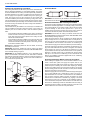
The above requirements shall be permitted to be waived where special
engineering, approved by the authority having jurisdiction, provides an
adequate supply of air for combustion, ventilation and dilution of flue
gases.
Be sure to instruct the owner not to block this intake pipe.
SECTION VII: CONDENSATE PIPING
CONDENSATE DRAIN TRAP AND DRAIN FREEZE
PROTECTION
Special precautions MUST be made if installing furnace in an area,
which may drop below freezing. This can cause improper operation or
damage to the equipment. If the furnace is installed in an area that has
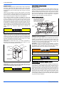
the potential of freezing, the drain line and the drain trap must be protected. Use a 3 to 6 watt per foot at 115 vac, 40º F (4.4° C) self-regulating, shielded and waterproof heat tape. Wrap the drain trap and the
drain line with the heat tape and secure with ties. Follow the heat tape
manufacturer's recommendations.
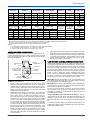
CONDENSATE DRAIN HOSE PART NUMBERS
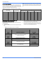
TABLE 15: Condensate Drain Hose
Part
Number
Hose
Number
Description
028-15156-000
#1
Drain tube - Condensate pan (Down flow)
028-15176-000
#2
Drain tube - Inducer (Horizontal RT.)
028-15168-000
#3
Drain tube - Inducer (Down flow)
028-15176-000
#4
Drain tube - Rain gutter
(Down flow & Horizontal RT.)
028-15176-000
#5
Drain tube - After Tee (Down flow)
028-15196-000
#6
Drain tube – Upper rain gutter
(Horizontal LT.)
-Vent system / Down flow)
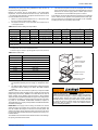
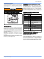
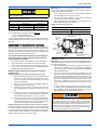
CONDENSATE DRAIN TUBE 5/8” (1.59 cm)
028-15169-001
#7
Drain tube - After Tee (Horizontal RT.)
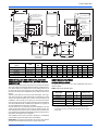
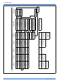
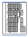
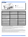
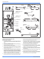
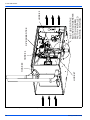
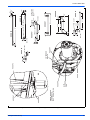
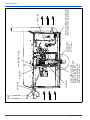
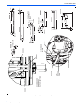
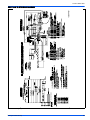
FIGURE 27: Condensate Drain Internal Hose Routing
028-13309-004
#8
Drain tube - P-trap (All models)
CONDENSATE DRAIN
028-15158-000
#9
Drain tube - Vent system (Horizontal LT.)
The condensate drain connection is provided in the furnace for field
installation. It consists of the hoses shown in Table 15, a NPT male connection, and a 1/2” (1.27 cm) female x 3/4” (1.9 cm) PVC slip coupling.
Some of the drain hoses will be needed to convert the condensate drain
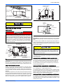
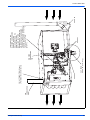
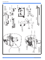
system when the furnace is installed in a horizontal left or right configuration. Refer to Figures 28 - 34 for the condensate hose sizes for condensate drain connections.
- Before Tee (Horizontal RT.)
028-15197-000
#10
Drain tube – Condensate pan (Horizontal –
drain closer to the front of the furnace, both
LT & RT)
Hoses #2, #4, #5, along with a barbed nipple, and a barbed tee are part
of condensate hose assembly 028-15176-000.
IMPORTANT: The condensate drain from the furnace may be connected in common with the drain from an air conditioning coil if allowed
by local code.
DOWNFLOW/HORIZONTAL CONDENSATE
INTERNAL DRAIN CONFIGURATIONS
IMPORTANT: Condensate must be disposed of properly. Follow local
plumbing or wastewater codes. The drain line must maintain a 1/4" per
foot (0.635 cm per meter) slope to the drain.
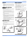
Downflow - Refer to Figure 28
Unitary Products Group
Furnace is shipped with one end of condensate hose #2 left open in the
furnace. If the provided Wye's drain is aligned with the opening in the
top of the furnace, hose #2 can be used. If it is desired that the Wye and
street elbow assembly point away from the opening in the casing top,
then the #2 hose will have to be replaced with provided #9 hose. The
dogleg end of hose #9 hose should be installed on the drain of the Wye.
21