1
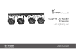
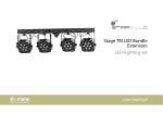
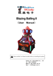
LED WALL TRI
LCG-027A
User Manual
Please read the instructions carefully before use
1
1. SAFETY INSTRUCTIONS:
•
•
•
•
•
•
•
•
•
•
•
•
•
•
•
•
Please keep this User Manual for future consultation. If you sell the unit to
another user, be sure that they also receive this instruction booklet.
Unpack and check carefully there is no transportation damage before using the
fixture.
Before operating, ensure that the voltage and frequency of power supply match
the power requirements of the fixture.
It’s important to ground the yellow/green conductor to earth in order ot avoid
electric shock.
Disconnect main power before servicing and maintenance.
Use safety chain when fixes this fixture. Don’t handle the fixture by taking its
head only, but always by taking its base.
Maximum ambient temperature is TA: 40°C. Don’t operate it where the
temperature is higher than this.
Don’t connect the device to any dimmer pack.
Make sure there are no flammable materials close to the unit while operating, as
it is fire hazard.
The housing or the lenses must be replaced if they are visibly damaged
Do not allow children to operate the unit.
Replace fuse only with the same type.
Never try to repair the unit by yourself. Repairs carried out by unskilled people
can lead to damage or malfunction. Please contact the nearest authorized
technical assistance center.
Disconnect the mains power if the unit is not used for a long time
Do not look directly at the Led Light beam while the unit is on
To prevent or reduce the risk of electrical shock or fire, do not expose the fixture
to rain or moisture.
2. INSTALLATION:
•
•
The unit should be mounted via its screw holes on the bracket. Always ensure
that the unit is firmly fixed to avoid vibration and slipping while operating.
Always ensure that the structure to which you are attaching the unit is secure
and is able to support a weight of 10 times of the unit’s weight. Also always use
a safety cable that can hold 12 times of the weight of the unit when installing the
fixture.
The unit must be fixed by professionals. And it must be fixed at a place where is
out of the touch of people and has no one pass by or under it.
2
3. TECHNICALS SPECIFICATIONS
•
•
•
•
•
•
•
•
•
•
•
•
•
Led: 18 x 3W TRI RGB
Beam angle: 40°
Black Housing
Dual yoke for floor mounting
Led display
Power In & Out, DMX In & Out
IP rate: IP65
Operations Modes: Built-in Program / Auto Run / DMX / Master Slave / Static
Colors
DMX-512: 1 / 3 / 4 / 4 / 6 channels selectable
Power Consumption: 60W
Power supply: 120V-60Hz
Size: 32.15 x 21.5 x 19.2 cm
Weight: 5.0 kg
4. OPERATIONS:
1. BUILT-IN Program
a. Press MODE button, Pr
b. Press UP or DOWN button, select the effect program Pr-01-Pr.10. When
LED display show Pr.01, press SETUP button enter the static color edit,
press UP or DOWN button , to choose the 7 kinds of static color ( 1-r; 2rg; 3-g; 4-gb; 5-b; 6-rb; 7-rgb), when it shows 7-rgb press the “SETUP” to
adjust the brightness for the red, green, blue through the “UP” or
“DOWN”, press the “SETUP” again to set up the strobe for the color
3
“FSXX”, press the “UP” or “DOWN” to adjust the speed for the strobe
FS00~FS99.
c. When LED display show Pr.02-Pr.1, first time press “SETUP”, it will show
“SP.XX”, then you can set up the speed for the program through pressing
“UP” or “DOWN”, SP01~SP100(FL); second time to press the “SETUP”, it
will shows “FSXX”, then you can adjust the strobe speed through pressing
the “UP” or “DOWN”, FS00~FS99.
2. Auto run mode
Press MODE button, enter auto run mode menu “AUTO”, the light will be
auto run 9 kinds of built-in program Pr.02-Pr.1. The user can set up the
running speed, the strobe speed under the built in program. Pr.02-Pr.10
then it will run according to the program which has been set up.
3. DMX mode
A. Press MODE button, enter DMX mode menu “d..xxx »
B. Press UP or DOWN button, setup DMX address d.001-d.512
C. Press SETUP button, setup DMX mode menu X-ch
D. Press UP or DOWN button, setup DMX mode 1-ch, 3-ch, 4-ch-1, 4-ch-2, 7-ch four
kinds of working mode
DMX MODE 1: 1 CHANNEL ( 1C )
CHANNEL
DMX VALUE
FONCTION
0
No Use
1-22
Red
23-45
Green
46-68
Blue
69-91
Blue-Green
92-114
Yellow
115-137
Orange
138-160
Pink
161-183
Purple
184-206
Dark Blue
CH 1
4
207-229
Pale Green
230-252
White
253-255
Warm White
DMX MODE 2: 3CHANNELS ( 3C )
CHANNEL
1
2
3
VALUE
0-255
0-255
0-255
FUNCTION
RED
GREEN
BLUE
DMX MODE 3: 4 CHANNELS ( 4C-1 )
CHANNEL
1
2
3
4
VALUE
0-255
0-255
0-255
0-255
FUNCTION
Master Dimmer
Red
Green
Blue
DMX MODE 4: 4 CHANNELS ( 4C-2 )
CHANNEL
1
2
3
4
VALUE
0-255
0-255
0-255
0-255
FUNCTION
Master Dimmer
Red
Green
Blue
DMX MODE 5: 6 CHANNELS ( 6C )
CHANNEL
VALUE
CH1
0-255
Red adjustment
Choose the
static color ( it
is available
when the 6
0-255
0-8
9-17
18-26
27-35
5
FUNCTION
Master Dimming
Red color dimming
R255
R255 G50
R255 G150
R255 G255
channel is 0-25)
CH2
Speed
adjustment
( control the
CH6 ( 26-255)
speed )
CH3
CH4
CH5
36-44
45-53
54-62
63-71
72-80
81-89
90-98
99-107
108-116
117-125
126-134
135-143
144-152
153-161
162-170
171-179
180-188
189-197
198-206
207-215
216-224
225-233
234-242
243-251
252-255
R200 G255
R100 G255
R40 G255
G255
G255 B50
G255 B150
G255 B255
G150 B255
G50 B255
B255
R50 B255
R150 B250
R255 B255
R220 B50
R150 G50 B100
R50 G220 B100
R50 G220 B100
R150 G220
R150 G220
G180 B220
G220 B50
R220 G100 B50
R220 G200 B100
R255 G200 B150
R255 G255 B255
0-255 slow-fats
0-255
0-255
Green adjustment
0-255
Blue adjustment
0-9
NO FUNCTION
10-255
STROBE ( slow-fats)
In CH2 can choose 29 kinds of
static color
Pr02 (7 color gradual change)
Pr03 (3 color gradual change)
Pr04 (7 color status step)
0-25
26-51
52-77
78-103
6
CH6
104-129
130-155
156-181
182-207
208-233
Pr05 (3 color status step)
Pr06 (dream 1)
Pr07 (dream 2)
Pr08 (red gradual change)
Pro9 (green gradual change)
234-255
Pr10 (blue gradual change)
4. MASTER/SLAVE MODE
Press MODE button, enter slave mode “SLAV”
The effect program of the master light on Built-in program or auto run mode is the
same with the slave light.
5. DMX512 CONNECTIONS:
The DMX512 is widely used in intelligent lighting control, with a maximum of 512
channels.
DMX 512
120 OHM 1/4W
COMMON
INPUT
•
•
•
1
DMX +
3
2
DMX -
7
•
•
•
1
3
2
OUTPUT
Termination reduces signal errors and to avoid signal transmission problems and interference. It is always
advisable to connect a DMX terminal. (resistance 120ohm 1/4W ) between pin2 (DNX-) and pin3 (DMX+)
of the last fixture.
1. Connect the fixture together in a “daisy chain” by XLR plug cable from the output
of the fixture to the input of the next fixture. The cable cannot be branched or
split to a 2Y” cable. Inadequate or damaged cables, soldered joints or corroded
connectors can easily distort the signal and shut down the system.
2. The DMX output and input connectors are pass-through to maintain the DMX
circuit when no power is connected to the fixture.
3. At last fixture, the DMX cable has to be terminated with a terminator to reduce
signal errors. Solder a 120-ohm 1/4W resistor between pin 2(DMX-) and pin
3(DMX+) into a 3-pin XLR-plug and plug it in the DMX-output of the last fixture.
4. Each lighting fixture needs to have an address set to receive the data sent by the
controller. The address number is between 0-511 (usually 0 & 1 are equal to 1).
5. 3 pin XLR: Pin 1: GND, Pin 2: Negative signal (-), Pin 3: Positive signal (+).
Notice:
A. If no any touch the button within 20 seconds, the LED display will be close, if touch
any button at this time, the LED display will be recover the original status. All the button
will be recover the function,
B. This fixture have the excess temperature self defective function. When the brightness
is obvious reduce, please check if the fan work in normal, after clear the trouble clear,
please power supply, the light will be release defend, and work in normal.
C. Turn on the fixture, it will show the Version No. like V2.0. It will keeps two seconds,
then under the working mode which the user set up.
8. TROUBLESHOOTING
Following are a few common problems that may occur during operating. Here are some
suggestions for easy troubleshooting:
• The fixture does not work, no light & the fan does not work:
1. Check the connection of power and main fuse.
2. Measure the mains voltage on the main connector.
• Not responding to DMX controller:
1. DMX LED should be on. If not, check DMX connectors, cables to see if link
properly.
2. If the DMX Led is on and no response to the channel, check the address settings
and DMX polarity.
3. If you have intermittent DMX SIGNAL problems, check the pins on connectors or
on PCB of the fixture or the previous one.
4. Try to use another DMX controller
5. Check if the DMX cables run near or run alongside to high voltage cables that
may cause damage or interference to DMX interface sircuit.
8
•
•
No response to the sound:
1. Make sure the fixture does not receive DMX signal
2. Check microphone to see if it is good by tapping the microphone.
One of the channels is not working well:
1. The stepper motor might be damaged or the cable connected to the PCB is
broken
2. The motor’s drive IC on the PCB might be out of condition.
9. FIXTURE CLEANING:
The cleaning of internal must be carried out periodically to optimize light output.
Cleaning frequency depends on the environment in which the fixture operates: damp,
smoky or particularly dirty surrounding can cause greater accumulation of dirt on the
fixture’s optic.
• Clean with soft cloth using normal glass cleaning fluid.
• Always dry the parts carefully
• Clean the external optics at least every 20 days. Clean the internal optics at least
every 30/60 days.
9