1
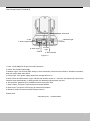
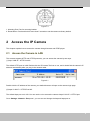
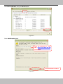
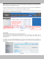
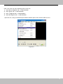
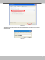
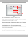
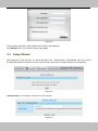
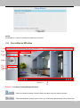
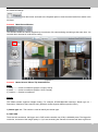
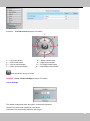
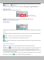
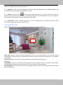
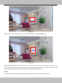
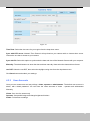
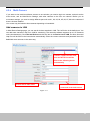
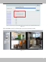
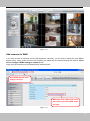
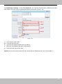
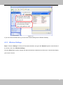
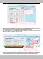
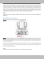
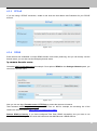
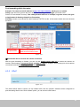
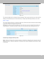
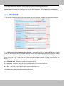
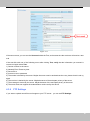
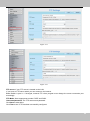
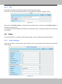
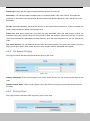
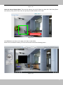
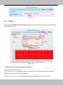
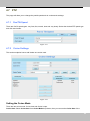
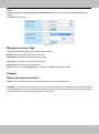
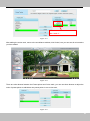
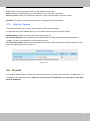
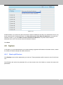
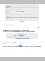
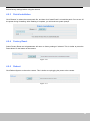
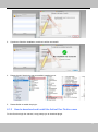
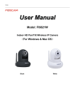
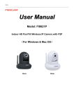
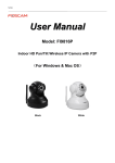
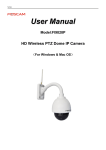
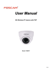
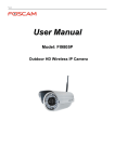
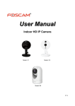
User Manual (For Windows & Mac OS) Indoor HD Wireless IP Camera Model: 2864-222, 2864-226 Color:Black/White V1.6 Table of Contents Table of Contents ................................................................................................................................................. 1 1 Overview ......................................................................................................................................................... 1 1.1 Key Features ........................................................................................................................................ 1 1.2 Read Before Use .................................................................................................................................. 2 1.3 Package Contents ................................................................................................................................ 2 1.4 Physical Description ............................................................................................................................. 2 2 Access the IP Camera .................................................................................................................................... 4 2.1 Access the Camera in LAN .................................................................................................................. 4 2.2 Access the Camera in WAN ................................................................................................................. 8 2.2.1 Static IP Addresses .................................................................................................................... 8 2.2.2 Dynamic IP Addresses ............................................................................................................... 9 2.3 Using the VLC player ......................................................................................................................... 12 2.4 IP camera connection to the server ...................................................................................................... 15 3 Surveillance Software GUI ........................................................................................................................... 15 3.1 Login Window ..................................................................................................................................... 16 3.2 Modify the Username and Password ................................................................................................. 16 3.3 Setup Wizard ...................................................................................................................................... 17 3.4 Surveillance Window .......................................................................................................................... 19 4 Advanced Camera Settings .......................................................................................................................... 27 4.1 Status.................................................................................................................................................. 27 4.1.1 Device Information ................................................................................................................... 27 4.1.2 Device Status ........................................................................................................................... 28 4.1.3 Session Status ......................................................................................................................... 28 4.1.4 Log ........................................................................................................................................... 28 4.2 Basic Settings..................................................................................................................................... 29 4.2.1 Camera Name .......................................................................................................................... 29 4.2.2 Camera Time............................................................................................................................ 29 4.2.3 User Accounts .......................................................................................................................... 30 4.2.4 Multi-Camera............................................................................................................................ 33 4.3 Network .............................................................................................................................................. 38 4.3.1 IP Configuration ....................................................................................................................... 38 4.3.2 Wireless Settings ..................................................................................................................... 39 4.3.3 PPPoE ...................................................................................................................................... 42 4.3.4 DDNS ....................................................................................................................................... 42 4.3.5 UPnP ........................................................................................................................................ 43 4.3.6 Port ........................................................................................................................................... 44 4.3.7 Mail Settings............................................................................................................................. 46 4.3.8 FTP Settings ............................................................................................................................ 47 4.3.9 P2P .......................................................................................................................................... 49 4.4 Video .................................................................................................................................................. 49 4.4.1 Video Settings .......................................................................................................................... 49 4.4.2 On Screen Display ................................................................................................................... 50 1 1 4.4.3 Privacy Zone ............................................................................................................................ 50 4.4.4 Snapshot Settings .................................................................................................................... 52 4.4.5 IR LED Schedule ..................................................................................................................... 52 4.5 Alarm .................................................................................................................................................. 53 4.6 Record ................................................................................................................................................ 56 4.6.1 Storage Location ...................................................................................................................... 56 4.6.2 Alarm Recording ...................................................................................................................... 57 4.6.3 Local Alarm Recording ............................................................................................................. 57 4.6.4 Scheduled Recording............................................................................................................... 58 4.6.5 SD Card Management ............................................................................................................. 59 4.7 PTZ ..................................................................................................................................................... 60 4.7.1 Pan/Tilt Speed .......................................................................................................................... 60 4.7.2 Cruise Settings ......................................................................................................................... 60 4.7.3 Start-Up Options ...................................................................................................................... 64 4.8 Firewall ............................................................................................................................................... 64 4.9 System................................................................................................................................................ 65 4.9.1 Back-up& Restore .................................................................................................................... 65 4.9.2 System Upgrade ...................................................................................................................... 66 4.9.3 Patch Installation ...................................................................................................................... 68 4.9.4 Factory Reset ........................................................................................................................... 68 4.9.5 Reboot...................................................................................................................................... 68 5 Playback ....................................................................................................................................................... 69 6 Appendix ....................................................................................................................................................... 70 6.1 Frequently Asked Questions .............................................................................................................. 70 6.1.1 How to install the plug-in for Safari ......................................................................................... 70 6.1.2 How to download and install the ActiveX for Firefox users .................................................... 71 6.1.3 How to download and install the ActiveX for Google Chrome users ...................................... 72 6.1.4 I have forgotten the administrator password ........................................................................... 74 6.1.5 Camera can not record ............................................................................................................ 74 6.1.6 Subnet doesn’t match .............................................................................................................. 74 6.1.7 No Pictures Problems .............................................................................................................. 75 6.1.8 Can’t access IP camera in internet .......................................................................................... 76 6.1.9 UPnP always failed .................................................................................................................. 76 6.1.10 Camera can not connect wireless ......................................................................................... 76 6.1.11 Can’t see other cameras listed .............................................................................................. 76 6.2 Default Parameters ............................................................................................................................ 76 6.3 Specifications ..................................................................................................................................... 77 6.4 CE & FCC ........................................................................................................................................... 78 2 2 1 Overview Indoor HD Wireless IP Camera with P2P is an integrated wireless IP Camera with a color CMOS sensor enabling viewing in High Definition resolution. It combines a high quality digital video camera, with a powerful web server, to bring clear video to your desktop and mobile devices from anywhere on your local network or over the Internet. Thanks to the P2P easy access technology, you don’t need to do complicated Port Forwarding and DDNS settings, you just need to scan the QR code on the bottom of the camera to connect it on smart phone, or input the UID on CMS software to do remote access. With flexible 300-degree pan and 120-degree tilt(except for FC1403P), the IP Camera gives users more comprehensive control over a monitored site. The camera supports H.264 video compression technology, dramatically reducing file size and saving network bandwidth. The camera is based on the TCP/IP standard. There is a WEB server inside which could support Internet Explore. Therefore the management and maintenance of your device is simplified by using the network to access the website of your camera. The camera is designed for indoor surveillance applications such as home, retail store and office. Controlling the camera and managing images is simplified by using the provided web interface across the network utilizing wired or wireless connectivity. The IPCAM supports Smart Phone APP for Android and iPhone users, please search and install IPCam Viewer on Google Play for Android devices, search and install IPCam_Viewer on APP Store for iOS devices, then you can view your camera anywhere, anytime on your smart mobile devices. 1.1 Key Features Standard H.264 video compression algorithm to satisfy the transmission of high definition video in narrow bandwidth network P2P feature for easy access Megapixel HD video Pan 300 degree, tilt 120 degree Supports IE/Firefox/Google/Safari browser Supports WEP,WPA-PSK and WPA2-PSK Encryption Wireless connection is compliant with IEEE 802.11b/g/n Wi-Fi, up to 150Mbps IR night vision (Range: 8m) Supports image snapshot Supports dual-stream Supports SD Card storage up to 32GB(except for FC1403P) Supports IR-Cut auto switch 1 1 Embedded free DDNS(dynamic domain name service) Service Support for Third Party Domain Name Service Supports two-way audio using select browsers and apps Multi-level users management with password protection Motion detection alert via email or upload image to FTP server Free Android and iPhone APP for viewing live video Supports recording schedule 1.2 Read Before Use Please first verify that all contents received are complete according to the Package Contents listed below. Before the IP Camera is installed, please carefully read and follow the instructions in the Quick Installation Guide to avoid damage due to faulty assembly and installation. This also ensures the product is used properly as intended. 1.3 Package Contents ● IP Camera × 1 ● Mounting bracket × 1 ● Wi-Fi Antenna × 1 ● Ethernet Cable × 1 ● DC Power Adapter × 1 1.4 Physical Description Front Panel 1.Speaker 2.LENS 3.Infrared LED 4.Microphone Figure 1.1 1.Speaker: Built-in speaker 2.LENS: Fixed focus lens. 3.Infrared LED: Infrared LEDs for night vision 4.Microphone: Built-in microphone 5.Wi-Fi Antenna: Wireless Antenna 2 2 Rear Panel(FC2401P/FC2503PZ) 9.Antenna 1.LAN 7.Audio Output 3.Network light 2.Power 4.Power light 8.Audio Input 5.WPS 6. SD Card Slot Figure 1.2 1.LAN: 10/100 Mbps RJ-45 port for wired connection 2.Power: DC 5V/2A Power supply 3.Network Light: The LED will blink slowly in wired connection, blink two times faster in wireless connection, blink four times faster when WPS 4.Power Light: If the power supply works fine, the light will turn on 5.WPS: Push the WPS button on the camera and wireless router in 1 minutes, the camera will connect the wireless router automatically, in WPS process, the Network Light will blink very fast 6. SD card Slot: Supports up to 32GB SD card for storing the video 7.Audio Output: This jack is used to plug an external speaker 8.Audio Input: This jack is used to plug an external microphone 9.Antenna: Used to connect external wireless antenna Bottom View 1.Mounting Port 2.Reset Button 3 3 Figure 1.3 1. Mounting Port: Port for mounting bracket 2. Reset Button: Push and hold for more than 5 seconds to set the camera to factory default. 2 Access the IP Camera This chapter explains how to access the camera through browser and RTSP player. 2.1 Access the Camera in LAN This camera supports HTTP and HTTPS protocols, you can access the camera by two ways. (1) http:// LAN IP + HTTP Port NO. The default HTTP port no is 88. Double click the IP Camera Tool icon to run, and it should find the camera’s IP address automatically after you plug in the network cable. Figure 2.1 Double click the IP address of the camera; your default browser will open to the camera login page. (2) https:// LAN IP + HTTPS Port NO. The default Https port no is 443. You can use the url to access the camera: https:// LAN IP + HTTPS port. Go to Settings - Network - Port panel , you can see and change the http and https port no. 4 4 Figure 2.2 HTTPS(Hypertext Transfer Protocol over Secure Socket Layer) is a safe way to access your camera, the data transferred on the Internet will be encrypted. Since we can not apply license for every LAN or DDNS URL, the webpage may pop up a warning like the following picture, you just need to click 'Continue to this website (not recommended). ' Open Internet Explorer if it is not already opened. Click on Tools, then click Internet Options. Next, click the Security tab, then click the Trusted sites button. 5 5 Figure 2.3 For Firefox, you can add the trusted as the following way: Tools ---- Options ---- Advanced --- View Certificates --- Servers Figure 2.4 6 6 Click View Certificates, and go to Servers option. Figure 2.5 Go to Add Exception panel. Enter the camera’s url , here take https://192.168.8.129:443 for example . Click this button to add it . Figure 2.6 7 7 2.2 Access the Camera in WAN 2.2.1 Static IP Addresses Users who have static IP addresses do not need to set DDNS service settings for remote access. When you have finished connecting the camera using the LAN IP address and port forwarding, you can access the camera directly from the Internet using the WAN IP address and port number. How to Obtain the WAN IP address from a public website To obtain your WAN IP address, enter the following URL in your browser: http://www.whatismyip.com.The webpage at this address will show you the current WAN IP. Figure 2.3 Access your IP Camera from the Internet You can access the IP Camera from the Internet (remote access). Enter the WAN IP address and port number in your standard browser. For example, you would enter http:// 183.37.28.254:85 NOTES: Make sure port forwarding is successful. You can do port forwarding two ways. 8 8 1) Login to your router to enable the “UPNP” function. You can then login to the camera as administrator, choose Network, and then choose UPnP to enable UPnP. Make sure that the status of UPnP reads “UPnP Successful” on the Device Status page. 2) Do port (HTTP port and Media port) forwarding manually. If your router has a Virtual Server, it can do port forwarding. Add the camera’s LAN IP and port which you had set earlier to your router’s port forwarding settings. If you plug the camera into a router, it will have a dynamic IP address and you need to set DDNS service settings to view it remotely. 2.2.2 Dynamic IP Addresses DDNS is a service that allows your IP Camera, especially when assigned with a dynamic IP address, to have a fixed host and domain name. This means that even though your WAN IP address is constantly changing, you will have a fixed hostname you can use to access your cameras at all times. You can access the camera directly from the Internet using the hostname and port number. What is the HTTP Port no.? Default HTTP Port is 88 All cameras have the default HTTP port of 88. For example, if the LAN IP link of the camera is http://192.168.1.110:88, this means that the camera’s HTTP port is 88. You can change port 88 to another port if you’d like such as 2000 or 8090, which will not be conflict with other existing ports like 25, 21,10000.Here you can set the port no. between 1 and 65535. Change the default http no.88 to another one. How to assign a different HTTP Port No. and fixed the LAN IP of the camera by the IP Camera Tool? Step 1: Open the IP Camera Tool, select the camera you would like to change the port of, right click on the IP address, and click on ”Network Configuration”, this brings up the network configuration box. Select which camera you’d like to change the port for, and right click Figure 2.4 9 9 Modify the Http Port. Enter the Username and password, click OK. Figure 2.5 Step 2: Enter the username and password of the Administrator (default username is admin with a blank password), and click “OK” to apply changes. Step 3: Wait around 10 seconds, you’ll see that the camera’s LAN IP address has changed. In our example it was changed to 2000, so we see http://192.168.1.110:2000 in IP Camera Tool. Also, the LAN IP address is now fixed at a static IP address of http://192.168.1.110:2000. This IP address will not change even if the camera is powered off and back on, the camera will remain on this LAN IP address. This is very important that a static LAN IP address is set, or you may have problems later with remote access and seeing the camera remotely if the camera loses power and reconnects on a different LAN IP address. Make sure you set a static LAN IP address! Figure 2.6 What is Port forwarding? If you have never done port forwarding before, you can open and view the following link to understand the basic concept. Port forwarding allows for outside connections to access a specific device on your network from anywhere in the world. Every router automatically blocks any incoming connections for safety purposes. Using port forwarding, you are telling your router to allow a connection through a certain port (you can think of it as a gateway) into your router. You set this port to a specific device, in our case an IP Camera, so it can be accessed from anywhere in the world. Click this link to learn more about port forwarding: http://portforward.com/help/portforwarding.htm How do we configure Port Forwarding? For this section, we will be using an example: Let’s say the camera’s LAN IP address is http://192.168.8.100:2000 10 10 Step 1: Login to the router, and go to your router’s port forwarding or port triggering menu. Sometimes this is also under the name of Virtual Server or NAT. Using the Linksys brand router as an example, we would log into the router, and go to the Applications & Gaming menu. We would then click on the “Single Port Forwarding” sub-menu. Step 2: Create a new column using the LAN IP address & HTTP Port of the camera within the router as shown below, then push OK or Submit to save your settings: Fill the HTTP Port of the camera in the columns of External Port and Internal Port. Example: 2000 Fill in this section with the LAN IP of the camera; we would enter “100” for our example. Assign a name for the port forward setting here. Figure 2.7 First method : Use the embedded DDNS to access the camera via the Internet Each camera has an embedded unique DDNS domain name, the format of this domain name is xxxxxx.myipcamera.org. On the bottom of the camera, you can see the domain name sticker with this information on it. For example, we can use test09.myipcamera.org. In the camera, click Settings at the top, click “Network” on the left, then click “DDNS” to get to the DDNS settings page. Here you can see the unique domain name of your camera. Figure 2.8 11 11 Now you can use “http://Domain name + HTTP Port” to access the camera via the Internet. Take hostname a33471.myipcamera.org and HTTP Port of 2000 for example, the URL link to access the camera via the Internet would be http:// a33471.myipcamera.org:2000. Second method : Use the Third party DDNS to access the camera via the Internet Step 1 Please go to the third party DDNS website(such as www.no-ip.com) to create a free hostname. Step 2 DO DDNS Service Settings within the Camera Please set DDNS Settings within the camera by hostname, a user name and password you’ve got from www.no-ip.com Take hostname ycxgwp.no-ip.info, user name ipcamera, password ipcamera2012 for example. Firstly, goes to option of DDNS Settings on the administrator panel. Secondly, select No-Ip as a server. Thirdly, fill ip camera as DDNS user, fill password ipcamera2012 as DDNS password, fill ycxgwp.no-ip.info as DDNS domain and server URL, Then click save to make effect. The camera will restart and to take the DDNS settings effective. Fourthly, after the restart, login the camera, and go to option of Device Status on the administrator panel, and check if the DDNS status is successful. If failed, please double check if you have input the correct hostname, user name, and password, and try to redo the settings. NOTE: If you have set Third Party DDNS successfully ,the Domain Name will be invalid. The Third Party DDNS and the Domain Name cannot work at the same time, the last time you configured will take effect. 2.3 Using the VLC player This camera supports RTSP streaming, here you can view the camera using VLC player. RTSP URL rtsp:// [user name][:password]@IP:HTTP port number/videosream The part in the square brackets may be omitted. user name & password: The user name and password to access the camera. This part can be omitted. IP: WAN or LAN IP address. Videostream: Here support three mode: videoMain, videoSub and audio. When the network speed is bad, here you had better select videoSub. If you select audio, you can only hear the sound but cannot see the video. For example: IP: 192.168.1.11 HTTP Port number: 88 User name: admin Password: 123 12 12 Here I can enter one of the following URLs in the VLC. 1) rtsp://admin:[email protected]:88/videoMain 2) rtsp:// @192.168.1.11:88/videoMain 3) rtsp://:[email protected]:88/videoMain 4) rtsp://[email protected]:88/videoMain Open the VLC, and go to MediaOpen Network Stream option, then enter the URL into VLC. Figure 2.9 13 13 Figure 2.10 Sometimes you may need to enter the user name and password again. Click OK and you can see the real-time preview. Figure 2.11 14 14 Figure 2.12 If you cannot play the video in the VLC player, please check the port mapping. You can read Quick Installation Guide about How to configure port forwarding. NOTE: If you modify the camera’s username or password, you had better reboot the camera, or else the new username and password cannot take effect when you enter the authentication in the VLC. 2.4 IP Camera Connection to the Server Device supports ONVIF2.2.1 protocol,You can easily access the NVR with ONVIF or server with ONVIF. 3 Surveillance Software GUI Please refer to the Quick Installation Guide if you install the camera at first time. After finishing quick installation, you can take time to learn the operation of the software. 15 15 3.1 Login Window 1 2 3 4 Figure 3.1 Please check the login window above, it was divided to 5 sections from no. 1 to 4. Section1 Enter the User name and password The default administrator username is admin with a blank password. When you first log in you will be required to change this to prevent unauthorized users logging into the camera. Section2 Stream The camera supports two stream modes: Main stream and sub stream. If you want to access the camera form LAN, here you can select Main stream. If you want to access the camera from Internet, here we recommend sub stream. Note: When the network bandwidth is badly you’d better select Sub Stream and the video will be more fluency. Section3 Select the language You can select the language you need via click on the language drop-down list to switch. Section4 Login the camera Click Login button and you will see the surveillance windows.(If login the camera for the first time, the page that modify the username and password will appears.) 3.2 Modify the Username and Password When you log in for the first time, it will require that you modify the username and password automatically. 16 16 Figure 3.2 Enter the New Username, New password and Confirm the password. Click Modify button, you will see the login page again. 3.3 Setup Wizard After logging in for the first time, you will be directed to the“Setup Wizard”automatically. Here you can set the basic parameters of camera, such as camera name, camera time, wireless settings, IP configuration. Figure 3.2 Camera Name: You could give a name for your IP camera. Figure 3.3 17 17 System Time: Select the time zone you need to set the date, time,format, etc. Figure 3.4 Wireless networks: Click Scan, find the SSID of your wireless router, select and enter the password. Figure 3.5 IP: Set the IP address of the camera. You could choose to obtain an IP automatically (DHCP) or set the IP address manually according to your needs. 18 18 Figure 3.6 NOTE: It takes about 1 minute to connect the camera to your router. 3.4 Surveillance Window 1 2 8 3 4 5 6 7 Figure 3.3 9 Section1 LiveVideo / Settings/Playback buttons : Path to surveillance window. Click this button and back to the surveillance window : Path to Administrator Control Panel, Click it, and it will lead to Administrator Control Panel and 19 19 do advanced settings. : Click this button and back to the Playback panel to view the stored audio files stored in the SD Card. Section2 Multi-Device Window The firmware inside the camera supports up to maximum of 9 cameras being monitoring at the same time. You can add other cameras in multi-device setting. Figure 3.4 Section3 Mode/ Stream / Mirror/ Flip buttons/Zoom Mode 1) 50HZ ---------Indoor surveillance (Region: Europe, China) 2) 60HZ ---------Indoor surveillance (Region: USA, Canada) 3) Outdoor------Outdoor surveillance Stream The default stream supports multiple modes, For example: 0/720P/30fps/2M meanings: Stream type no. / Resolution / Maximum frame rate/ Bit rate. (Different models support different specific mode. ) 1) Stream type no. : The number is used to identify the stream type. 2) 720P/ VGA There are two resolutions, the bigger one is 720P, and the smaller one (VGA) is 640x480 pixels. The bigger the resolution, the better of the image quality is. If you are accessing the camera via internet and want to get more 20 20 fluid video streaming, please select resolution VGA. 3) Maximum frame rate When the video format is 50Hz, the maximum frame rate is 25 fps. When the video format is 60Hz, the maximum frame rate is 30 fps. You should lower frame rate when the bandwidth is limited. Normally, when the frame rate above 15, you can achieve fluid video. 4) Bit rate Generally speaking, the larger the bit rate is, the clearer video will become. Lower bandwidth may require a lower bitrate for optimal video performance. You can reset the stream type on Settings-> Video-> Video Settings panel. Figure 3.5 After changing, please re-login the camera and you can see the modification. Zoom Control(Only FC2503PZ) Zoom the camera’s lens. Zoom the camera’ lens. You can adjust the speed of the lens’ zoom at Settings--PTZ--Pan & Tilt Speed--Zoom speed. 21 21 Section4 Pan/Tilt Control(except for FC1403P) 1 6 5 3 4 8 7 2 1----- Up control button, 3----- Left control button, 5----- Up-Left control button 7----- Down-Left control button 2----- Down control button, 4----- Right control button, 6----- Up-Right control button 8----- Down-Right control button Click this button and go to center Section5 Cruise / Preset settings(except for FC1403P) Cruise Settings The default cruise tracks have two types: Vertical and Horizontal. Vertical: The camera will rotate from up to down. Horizontal: The camera will rotate from left to right. 22 22 : Start cruise. : Stop cruise. If you want to define or change the cruise trace, please go to Settings PTZ Preset Settings panel. How to do cruise? Firstly: Select one track in the track drop-down list Select one of these Secondly: Click Start cruise button, the camera will cruise following the predefined path. Thirdly: Click stop button and finish cruising. Preset settings IPCAM supports 16 preset positions, which is considered enough for DIY home & small business surveillance market The default preset position is Topmost, Bottom most, Left most, right most, you can add other preset positions. Add Click this icon to save the position you need the camera to remember Delete Select one preset position and click this button to delete it. GO Select one preset position in the preset drop-down list and click Go to make the camera move the preset position How to do preset position? Firstly, move the camera and stop at a desired place where you want make preset position. Secondly, click button and enter a descriptive name for the preset position. The preset position cannot contain special characters. Then click OK to save it. If you want to reset the preset position, click Cancel. After that, you can move the camera and stop at another place, and set another preset position. You can do all the 16 preset positions with this method. If you want to see one preset position you have set, only select the preset position name from the preset drop-down list, and click go button, the camera will go to the preset position. 23 23 Section6 IR LED Lights Click Infra led and there are three modes to adjust the infrared led: Auto, Manual and Schedule. Auto: Select it and the camera will adjust the infra led (on or off) automatically. Manual: Select it and you can turn on or turn off the infrared led manually. Schedule: Select it and the IR led light will be off at the schedule period. If you want to define or change the IR led lights schedule time, please go to Settings--->Video---> IR LED Schedule page. Section7 Image quality settings In this page, you can tune Hue, Brightness, Contrast, Saturation, and Sharpness to get higher quality. Section8 OSD If you have added time and camera name in the video, you can see it in the live window. Go to Settings ---Basic settings---Camera name panel, and you can change another device name. The default device name is anonymous. Go to Settings ---Basic settings---Camera time panel and adjust the device time. Go to Settings ---Video---On Screen Display panel, you can add or no add OSD. Section9 Play/Stop/ Talk/Audio/ Snap/ Record/ Full screen button 1 2 3 4 5 6 7 1 ----- Play Click it to play the video of the camera 2 ----- Stop Click it to stop the video of the camera 3 ----- Talk Click the button and the icon will become to , then talk to the microphone that connected with PC, people around the camera can here your voice. Click the icon again and stop talking. 4 ----- Audio Click this icon, the icon will become to you can hear the sound around the camera by the 24 24 earphone or speakers that connected with PC. 5 ----- Snapshot Click it to make snapshot and it pop-up a window which picture you snapshot, right click in the window and save the picture to anywhere you want. 6 ----- Record Click the icon and the camera start recording, you can see a green dot in the live window. Click again and stop recording. The default storage path is C:\IPCamRecord. You can change the storage path: Go to Settings- >Record->Storage Location panel. 7 ----- Full Screen Click it to make full-screen, or you can double click the surveillance screen to make full-screen. Double click again and exit full-screen. Onscreen Mouse Control Right click the mouse and you can adjust the screen ration, full screen and Zoom up. Figure 3.6 Keep ratio: Select it and the camera will adjust the size of live window based on the computer monitor automatically. Sometimes there is a black border around the video, please select Keep ration to get a better visual quality . Full Screen: Select it and Click it to make full-screen, press ESC and exit full-screen. Zoom up: First Method: Here is a convenient and fast solution to Zoom up/down screen by Clicking Video Screen and adjusting Mouse pulley, or by press the CTRL key and click the mouse left button. Second Method: Click it and the live view will be digital zoomed up, then click Zoom Down and the live view back to original size. 25 25 Figure 3.7 When you select the Full Screen, then click right mouse, there is a Screen PTZ button. Figure 3.8 Click the Screen PTZ button and put the mouse on the screen to indicate the camera move direction you prefer, press the left mouse, the camera will move to the corresponding direction. Loosen the mouse and stop moving. Press Esc button or double click right mouse and cancel the function. NOTE: For Mac OS, the plugin cannot support Onscreen Mouse Control, so you cannot allow to use it. 26 26 4 Advanced Camera Settings Click the button “Settings”, goes to Administrator Control Panel to make advanced camera settings. 4.1 Status Status contains four columns: Device Information, Device Status, Session Status and Log, it will show you various information about your camera. 4.1.1 Device Information Figure 4.1 Camera Model: The camera model no. Camera Name: The Device Name is a unique name that you can give to your device to help you identify it. Click Basic Settings and go to Camera name panel where you can change your camera name. The default device name is anonymous. Camera ID: Display the wired MAC address of your camera. For example Device ID is 000C5D00008, the same MAC ID sticker is found at the bottom of the camera. Camera Time: The system time of the device. Click Basic Settings and go to Camera time panel and adjust the time. System Firmware version: Display the System Firmware version of your camera. App Firmware version: Display the application firmware version of your camera. Plug-in version: Display the plug-in version of your camera 27 27 4.1.2 Device Status On this page you can see device status such as Alarm status/ Record Status ,DDNS status ,WIFI status and so on. Figure 4.2 4.1.3 Session Status Session status will display which users are currently viewing the camera, as well as their IP address Figure 4.3 4.1.4 Log The log record shows who and which IP address accessed or logout the camera and when. 28 28 Click the page number and go to the corresponding page to see more logs. Fill in one page number, click Go button and go to the corresponding page. Figure 4.4 Reboot the camera and clear the log records. 4.2 Basic Settings This section allows you to configure your camera’s Name, Time, Mail, User account and Multi-Device. 4.2.1 Camera Name Default alias is anonymous. You can define a name for your camera here such as apple. Click Save to save your changes. The alias name cannot contain special characters. Figure 4.5 4.2.2 Camera Time This section allows you to configure the settings of the internal system clocks for your camera. 29 29 Figure 4.6 Time Zone: Select the time zone for your region from the drop-down menu. Sync with NTP server: Network Time Protocol will synchronize your camera with an Internet time server. Choose the one that is closest to your camera. Sync with PC: Select this option to synchronize the date and time of the Network Camera with your computer. Manually: The administrator can enter the date and time manually. Note select the date and time format. use DST: Select the use DST, then select the daylight saving time from the drop-down menu. Click Save button and submit your settings. 4.2.3 User Accounts Here you can create users and set privilege, visitor, operator or administrator. The default user account is admin, with a blank password. You can enter the users accounts of visitor 、operator and adminstrator Manually. Visitor: Can view live stream only Operator: Can pan/tilt image and change brightness/ir/colors Admin: Full access to settings 30 30 Figure 4.7 How to change the password of administrator? Firstly, select the account of administrator, then select “Change password”, enter the old password and the new password, lastly click modify to take effect. Figure 4.8 How to add account ? Select one blank column, then enter the new user name, password and privilege, last click Add to take effect. You can see the new added account on the Account list. 31 31 Figure 4.9 Figure 4.10 Delete:Select the account which you want to delete, then click Delete button to take effect. NOTE: The default admin account cannot be deleted, but you can add other administrator users. 32 32 4.2.4 Multi-Camera If you want to view multi-surveillance screens on one window, you need to login one camera, and set it as the main device, and do Multi-Device Settings, add other cameras to the first one camera. Before you do multi-cams settings, you need to assign different port such as 81, 82, 83, 84, 85, 86, 87, 88 to the cameras if there is 8 cams installed. Your rooter may be limited to less cameras depending on bandwidth. Add cameras in LAN In Multi-Device Settings page, you can see all devices searched in LAN. The 1st Device is the default one. You can add more cameras in the list in LAN for monitoring. The camera’s software supports up to 9 IP Cameras online simultaneously. Click The 2nd Device and click the item in the Device List in LAN, the Alias, Host and Http Port will be filled in the boxes below automatically. Enter the correct username and password then click Add. Add more cameras in the same way. 1 Click it, camera model, alias, host and HTTP Port will be filled in the following boxes automatically 3 Click Add to take effect 2 Enter the User name and password of the 2nd camera Figure 4.11 33 33 Figure 4.12 Back to Live Video, and click Four Windows option, you will see four cameras you added. Figure 4.13 34 34 Figure 4.14 Add cameras in WAN If you want to view all cameras via the internet(remote computer), you will need to add them using DDNS domain name. Firstly, make sure all of the cameras you added can be accessed through the internet. (Read How to configure DDNS settings in chapter 4.3.3) Login to the first camera using a DDNS domain name and port. Use DDNS domain name and port to login. Make sure each camera you need add could login with DDNS name and port. Figure 4.15 35 35 Click Multi-Device Settings. Choose The 2nd Device. Fill in the 2nd camera’s name, DDNS domain name, port number. Enter user name and password and then choose Add. (Figure 4.19) Figure 4.16 1----- The camera model: H264. 2----- The 2nd camera’s name 3----- Fill in the 2nd camera’s DDNS host not LAN IP 4---- Enter the 2nd camera’s user name and password 5---- Click Add button and to take effect NOTE: Here the Host must be entered as the second camera’s DDNS domain name, not its LAN IP. 36 36 Figure 4.17 Return to video window. You will see all of the cameras accessible through the internet. When you are away from home, you can use the first camera’s DDNS domain name and port to view all the cameras via internet. Figure 4.18 37 37 4.3 Network This section will allow you to configure your camera’s IP, PPPoE, DDNS, Wireless Settings, UPnP and Port. 4.3.1 IP Configuration If you want to set a static IP for the camera, please go to IP Configuration page. Keep the camera in the same subnet of your router or computer. Figure 4.19 Changing settings here is the same as using the IP Camera Tool. It is recommended that you use the subnet mask, gateway and DNS server from your locally attached PC. If you don’t know the subnet mask, gateway and DNS server, you can check your computer’s local area connection as follows: Control Panel Network Connections Local Area Connections Choose Support Details. Click here Figure 4.20 38 38 Set the same Subnet Mask and gateway of the camera with your PC. There are two DNS servers, you can set any of them. Same with gateway is also OK. Figure 4.21 If you don’t know the DNS server, you can use the same settings as the Default Gateway. 4.3.2 Wireless Settings Step 1: Choose “Settings” on the top of the camera interface, and go to the “Network” panel on the left side of the screen, then click “Wireless Settings.” Click the Scan button and the camera will detect all wireless networks around the area. It should also display your router in the list. 39 39 Click the Scan button to search for wireless networks. Click the Page number to see other wireless networks devices if there are more than 10. Figure 4.22 Step 2: Click the SSID (name of your router) in the list, the corresponding information related to your network, such as the name and the encryption, will be filled into the relevant fields automatically. You will only need to fill in the password of your network. Make sure that the SSID, Encryption and the password you filled in are exactly the same for your router. 2 Enter the password of your router Figure 4.23 1 Click the SSID of your router and the relevant information will be filled in the fields automatically. Step 3: Please click on the Save button after all settings have been entered and disconnect the network cable. Never shut down the power of the camera until the IP camera is able to connect to the wireless network. 40 40 The LAN IP address will disappear on the window of IP Camera Tool when the camera is configuring a wireless connection. Wait about 1 minute, the camera should obtain a wireless connection, and the LAN IP of the camera will show again on the window of the IP Camera Tool. The IP address may have changed after the camera receives a wireless connection; we recommend setting a static local IP address if this IP address changes by right clicking the camera in IP Camera Tools, setting a static IP, and pushing OK (see Figure4.36). Congratulations! You have set up the wireless connection of the camera successfully. NOTE: If you fail to make a wireless connection, please refer to your seller or contact us directly for assistance. WPS (Wi-Fi Protected Set-up) Step 01) Press and hold the WPS button for two seconds. WPS Button Step 02) Press the WPS button on your router within 60 seconds. The WPS button is usually on the back or side of your router. On some routers, you may need to log in to the web interface and click on an on-screen button to activate the WPS feature. If you are not sure where the WPS buttons is on your router, please refer to your router’s User Manual. The camera will automatically create a secure wireless connection to your router. If you have plugged in the network cable, please plug it out. The IP Camera Tool will search the camera’s LAN IP. Make sure the PC and the camera share the same subnet. NOTE: The security mode of router cannot be WEP, or else the WPS settings may be failed. 41 41 4.3.3 PPPoE If you are using a PPPoE connection, enable it and enter the User Name and Password for your PPPoE account. Figure 4.24 4.3.4 DDNS Each camera has embedded a unique DDNS domain name when producing, and you can directly use the domain name, you can also use the third party domain name. Ip camera domain name Here take a33471.myipcamera.org for example. Go to option of DDNS on the Settings->Network panel, you can see the domain name. Figure 4.25 Now you can use http:// Domain name + HTTP Port to access the camera via internet. Take hostname a33471.myipcamera.org and HTTP Port no. 800 for example, the accessing link of the camera via internet would be http:// a33471.myipcamera.org:8000 Restore DDNS to factory: If you have configured Third Party DDNS successfully, but you want to use Manufacturer’s DDNS again , here click this button and start Manufacturer’s DDNS Service. 42 42 Port forwarding within the router Example: The camera’s LAN IP address is http://192.168.8.100:2000 , Media port no. is 9200. Firstly, login the router, goes to the menu of Port Forwarding or Port Trigger (or named Virtue Server on some brands of router). Take Linksys brand router as an example, Login the router, and goes to Applications & Gaming->Single Port Forwarding. Secondly, Create a new column by LAN IP address & HTTP Port No. of the camera within the router showed as below. Assign a name as you like here Fill the Media Port no. of the camera on the column of External Port and Internal Port Figure 4.26 ③Use domain name to access the camera via internet After the port forwarding is finished, you can use the domain name+ http no. to access the camera via internet. Take hostname ycxgwp.no-ip.info and http no. 2000 for example, the accessing link of the camera via internet would be http:// ycxgwp.no-ip.info:2000 4.3.5 UPnP Figure 4.27 The default UPnP status is closed. You can enable UPnP, then the camera’s software will be configured for port forwarding. Back to the “Device Status” panel, you can see the UPnP status: 43 43 Figure 4.28 The camera’s software will be configured for port forwarding. There may be issues with your routers security settings, and sometimes may error. We recommend you configure port forwarding manually on your router. 4.3.6 Port This camera supports HTTP Port / HTTPS Port/ ONVIF Port. HTTP Port is used to access the camera remotely. If you want to access the camera and view the video. HTTP port : By default, the HTTP and Media port is set to 88. Also, they can be assigned with another port number between 1 and 65535. But make sure they can not be conflict with other existing ports like 25, 21. Figure 4.29 Another way to change the HTTP port NO. Step 1: Open the IP Camera Tool, select the camera you would like to change the port of, right click on the IP address, and click on ”Network Configuration”, this brings up the network configuration box as shown in Figure 4.35 and 4.36. 44 44 Select which camera you’d like to change the port for, and right click Figure 4.30 Modify the Http Port. Enter the Username and password, click OK. Figure 4.31 Step 2: Enter the username and password of the Administrator (default username is admin with a blank password), and click “OK” to apply changes. Step 3: Wait around 10 seconds, you’ll see that the camera’s LAN IP address has changed. In our example it was changed to 2000, so we see http://192.168.1.110:2000 in IP Camera Tool. Also, the LAN IP address is now fixed at a static IP address of http://192.168.1.110:2000 . This IP address will not change even if the camera is powered off and back on, the camera will remain on this LAN IP address. This is very important that a static LAN IP address is set, or you may have problems later with remote access and seeing the camera remotely if the camera loses power and reconnects on a different LAN IP address. Make sure you set a static LAN IP address! Figure 4.32 45 45 If the camera cannot be accessed, please make sure the port forwarding is successful. HTTPS port: The default port is 443. You can use the url to access the camera: https:// IP + HTTPS port. 4.3.7 Mail Settings If you want the camera to send emails when motion has been detected, here Mail will need to be configured. Figure 4.33 1----- SMTP Server/ Port /Transport Layer Security Enter SMTP server for sender. SMTP port is usually set as 25. Some SMTP servers have their own port, such as 587 or 465, and Transport Layer Security usually is None. If you use Gmail, Transport Layer Security must be set to TLS or STARTTLS and SMTP Port must be set to 465 or 25 or 587, which port you choose should be decided by which Transport Layer Security you select. 2-----SMTP Username/ password ID account and password of the sender email address 3----- Sender E-mail Mailbox for sender must support SMTP 4----- Receiver Mailbox for receiver need not support SMTP,you can set 4 receivers 5---- Save Click Save to take effect 6---- Test Click Test to see if Mail has been successfully configured. Click Test to see if Mail has been successfully configured. 46 46 Test result Figure 4.34 If the test success, you can see the Success behind the Test, at the same time the receivers will receive a test mail. If the test fails with one of the following errors after clicking Test, verify that the information you entered is correct and again select Test . 1) Cannot connect to the server 2) Network Error. Please try later 3) Server Error 4) Incorrect user or password 5) The sender is denied by the server. Maybe the server need to authenticate the user, please check it and try again 6) The receiver is denied by the server. Maybe because of the anti-spam privacy of the server 7) The message is denied by the server. Maybe because of the anti-spam privacy of the server 8) The server does not support the authentication mode used by the device 4.3.8 FTP Settings If you want to upload record files and images to your FTP server,you can set FTP Settings. 47 47 Figure 4.35 Figure 4.36 FTP server: If your FTP server is located on the LAN. If you have an FTP server which you can access on the internet. Port: Default is port 21. If changed, external FTP client program must change the server connection port accordingly. FTP Mode: Here supports two modes: PORT and PASV. Username/password: The FTP account and password. Click Save to take effect. Click Test to see if FTP has been successfully configured. 48 48 4.3.9 P2P Access the IP Camera by Smart Phone (Android or iOS operating system) First of all, you need to open the P2P function of the IP Camera at “Settings-->Network-->P2P”. Figure 4.37 Search and install IPCam Viewer on Google Play for Android devices, search and install IPCam_Viewer on APP Store for iOS devices. If you want to know more details of the iOS APP or Android APP, see the iOS App User Manual or Android APP User Manual. 4.4 Video This section allows you to configure Video stream settings, On screen display and Snapshot settings. 4.4.1 Video Settings There are two ways to set the stream video settings. They are main stream video settings and sub stream video settings. Figure 4.38 49 49 Stream type: There are four types to identify different streams you have set. Resolution: The camera supports multiple types, For example: 960P, 720P, VGA, QVGA. The higher the resolution is, the clearer video will become. But the code flux will become larger too, and it will take up more bandwidth. Bit rate: Generally speaking, the larger the bit rate is, the clearer video will become. Lower bandwidth way require a lower bitrate for optimal video performance. Frame rate: Note that a larger frame size takes up more bandwidth. When the video format is 50Hz, the maximum frame rate is 25 fps. When the video format is 60Hz, the maximum frame rate is 30 fps. You should lower frame rate when the bandwidth is limited. Normally, when the frame rate above 15, you can achieve fluid video. Key Frame Interval: The time between last key frame and next key frame. The shorter the duration, the more likely you will get a better video quality, but at the cost of higher network bandwidth consumption. 4.4.2 On Screen Display This page is used to add time-stamp and device name on the video. Figure 4.39 Display Timestamp: There are two options: Yes or NO. Select Yes and you can see the system date on the video. Display Camera Name: There are two options: Yes or NO. Select Yes and you can see the device name on the video. 4.4.3 Privacy Zone This page is used to set some mask as privacy zone on the video. 50 50 Figure 4.40 Allow On Screen Display Mask: There are two options: Yes or NO. Select Yes, then click “Set Privacy Zone” and draw a privacy area on the video, the privacy area will be black on the video. The mask area Figure 4.41 Click OK button and return to the page, click Save to take effect. Back to the surveillance window, you can see the mask area as the following picture: Figure 4.42 51 51 4.4.4 Snapshot Settings On this page you can set the snapshot pictures’ image quality and the storage path. Figure 4.43 Manual snap Quality: Low, Middle and High. The higher the quality, the picture will be clearer. Alarm Pictures Save To: FTP or SD Card. If you have done FTP and Alarm settings, when alarming, the camera will snap pictures to the FTP automatically. If you have selected a SD Card as the save path, make sure the camera has the SD card inserted. Enable timing to capture To enable capture interval, follow the steps below: 1 Select Enable timing to capture 2 Capture interval:The interval time between two captures. 3 Select the capture time Capture anytime Click the black button up the MON, you will see all time range turn red. When something moving in the detection area at anytime, the camera will capture. Specify an capture schedule Click the week day words, the corresponding column will be selected. For example, click TUE, the all column of TUE turns to red, that means during Tuesday whole day, the camera will capture. Press the left mouse and drag it on the time boxes, you can select the serial area, 4 Click Save button to take effect. 4.4.5 IR LED Schedule On this page you can set the schedule time for switching IR LED lights. When parameter Mode is set to the Schedule on the Live Video window, at these schedule time, the IR LED lights will be turned off. 52 52 Figure 4.44 4.5 Alarm IP Camera supports Motion Detection Alarm, when the motion has been detected, it will send emails or upload images to FTP. Figure 4.45 To enable motion detection, follow the steps below: Step 01: Enable Motion detection Step 02: Sensitivity---- Supports five modes: Lowest, Lower, Low, Medium and High. The higher the sensitivity, the easier the camera will be alarmed. Step 03: Trigger interval--- The interval time between two motion detections. Here supports 53 53 5s/6s/7s/8s/9s/10s/11s/12s/13s/14s/15s. Select one interval time. Step 04: Select the alarm indicator When the motion has been detected, the alarm status will turn to Detect alarm. Figure 4.46 There are four alarm indicators: A Camera Sound and PC Sound If the camera has connected with a speaker or other audio output device, if you select Camera Sound or PC Sound, when the motion has been detected, the people around the camera will hear beep alarm sound. B Send E-mail If you want to receive alarm emails when motion is detected, you must select Send E-mail and set Mail Settings first. C Take Snapshot If you select this checkbox, when the motion has been detected, the camera will snap the live view window as a still picture and load it to the FTP. Make sure you have set FTP and set FTP as the storage path in Video->Snapshot settings panel. Capture interval: The interval time between two pictures. D Recording(except for FC1403P) If you select this checkbox, when the motion has been detected, the camera will record automatically and store the record files to the SD Card. Make sure the camera has inserted SD card and you have set the SD card as the Alarm record files storage path, please go to Record—> Storage location page to verify this settings. The default alarm record time is 30s and pre-alarm record time is 5s, please go to Record—> Alarm Record page and change the alarm time settings. Step 05: Set detect area 54 54 Click set detect area a window will pop up, then you can draw the detection area. Click OK button after settings. When something moves in the detection area, the camera will alarm. Figure 4.47 Step 06: Alarm Schedule ①Alarm anytime when motion is detected Click the black button up the MON, you will see all time range turn red. When something moving in the detection area at anytime, the camera will alarm. Click this button and select all time range Figure 4.48 ②Specify an alarm schedule Click the week day words, the corresponding column will be selected. For example, click TUE, the all column of TUE turns to red, that means during Tuesday whole day, when something moving in the detection area, the camera will alarm. 55 55 Figure 4.49 ③Press the left mouse and drag it on the time boxes, you can select the serial area. Figure 4.50 Step 07: Click Save button to take effect. When the motion has been detected during the detection time in the detection area, the camera will alarm and adopt the corresponding alarm indicators. NOTE: You must set the detection area and detection schedule, or else there is no alarm anywhere and anytime. 4.6 Record This section will allow you to change the record files storage path and the record time. 4.6.1 Storage Location On this page you can change the alarm and manually recording storage path. 56 56 Figure 4.51 Recording Location: SD card or FTP. When the camera alarmed, it will store the alarm files to the SD card or FTP. Make sure the camera has been inserted the SD card. On this page, you can see the available space of the SD card. Local Recording Location: For Windows OS, the location recording path is c:/ IPCamRecord, you can change another one. For MAC OS, the manual recording path is: / IPCamRecord. 4.6.2 Alarm Recording On this page you can change the Pre-record time and Alarm record time. Figure 4.52 The default Pre-recorded time is 5s and the alarm record time is 30s, you can change another time, click Save button to take effect. 4.6.3 Local Alarm Recording On this page you can enable the local alarm record and Local Alarm record time. 57 57 Figure 4.53 4.6.4 Scheduled Recording On this page you can configure the schedule record. When the parameter Recording Location is set SD Card on the Storage Location page, you can configure parameters as shown in follow figure. Figure 4.54 When the parameter Recording Location is set FTP on the Storage Location page, you can configure parameters as shown in follow figure. 58 58 Figure 4.55 Click Save button to take effect. 4.6.5 SD Card Management This camera supports SD Cards up to 32G. When you insert the SD card while the camera is on, please reboot the camera. Go to the SettingsDevice StatusDevice Status page, you can see the SD card status. Figure 4.56 The default storage path of alarm record files is SD card, when the available size of SD card is less than 256M, the old record files will be deleted automatically. 59 59 4.7 PTZ This page will allow you to change the pan/tilt speed and do cruise tracks settings. 4.7.1 Pan/Tilt Speed There are five Pt speed types: very fast, fast, normal, slow and very slowly. Select the desired PTZ speed type and click save button . Figure 4.57 4.7.2 Cruise Settings This section explains how to add/ delete one cruise track. Figure 4.58 Setting the Cruise Mode There are two cruise mode: Cruise time and Cruise Loops. Cruise time: Select Cruise time from Cruise Mode drop-down, then you can set the Cruise time of the 60 60 camera. Cruise Loops:Select Cruise Loops from Cruise Mode drop-down, you can set the Cruise Loops of the camera. Click Save to take effect. Figure 4.59 Manage the Cruise Track There are two default cruise tracks: Vertical and Horizontal. Vertical: The camera will rotate from up to down Horizontal: The camera will rotate form left to right. Add: Add one cruise track, then click save button. Delete: Select one cruise track and delete it. Save: After you modify the Dwell time, you should click Save button to take effect. Example How to do add cruise tracks ? Firstly, Click Add button and enter a descriptive name to identify the cruise track. Secondly: On the lower left of the page, you can see all preset points you have added. Select one preset point and click Add button, you can see the preset point has been added to the cruise track on the cruise track page. You need to add two or more preset points to the cruise track. 61 61 The new added track name . 1 Select one preset point. 2 Click Add button. Here you can see the preset point has been added to one track. And you can set the stay time. Figure 4.60 Thirdly: Click OK button and the cruise track will take effect. You can add other cruise track as the same method. For example: I have added three preset points to the “track 1”, that means : When I select the “track 1” on the surveillance window, the camera moves as the following track: upright then Right Most last downleft. You can add preset on the left of the surveillance window. Add the preset. 62 62 The cruise tracks have added to the “track 1” . Figure 4.61 After adding the cruise track, return to the surveillance window, click Cruise, here you can see all cruise tracks you have added. Figure 4.62 There are other buttons between the Preset points and Cruise track, you can use these buttons to adjust the order of preset points or add/delete one preset points in one cruise track, Figure 4.63 63 63 Add: Select one preset points and add it to the selected cruise track. Delete: Select one preset points you have added to one cruise track, click delete. Move up/ down: Select one cruise track, adjust the order of preset points in one cruise track. Attention: TO prevent overheating of the motor, a long patrol time is not advised. 4.7.3 Start-Up Options This section will allow you to set the stop position after the camera reboots. It supports three modes: Disable Start-Up, Go To Home Position and Go To Preset Position. Disable Start-Up: When rebooting, the camera will not pan / tilt. Go To Home Position: When rebooting, the camera will pa Providing Central Management Software to manage or monitor multi-cameras n / tilt and stops at center. Go To Preset Position: Select one preset position and save it. When rebooting, the camera will pan/ tilt and stops at the preset position you have set. Figure 4.64 4.8 Firewall This section explains how to control the access permission by checking the client PC’s IP addresses. It is composed of the following columns: Block access from these IP addresses and Only allow access from these IP addresses. 64 64 Figure 4.65 Enable firewall, If you select Only allow access from these IP addresses and fill in 8 IP addresses at most, only those clients whose IP addresses listed in the Only allow access from these IP addresses can access the Network Camera. If you select Block access from these IP addresses, only those clients whose IP addresses are in the IP list cannot access the Network Camera. Click Save. 4.9 System In this panel, you can backup/restore your camera settings, upgrade the firmware to the latest version, restore the camera to default settings and reboot the device. 4.9.1 Back-up& Restore Click Backup to save all the parameters you have set. These parameters will be stored in a bin file for future use. Click Browse and select the parameters file you have stored, then click Submit to restore the restore the parameters. 65 65 Figure 4.66 4.9.2 System Upgrade Your current firmware version will be displayed on your screen. You may go to the Device Status Device Information Page to check for the latest firmware versions available. Click Browse, choose the correct bin file and then click System upgrade. Don’t shut down the power during upgrade. After upgrading, you can see the upgrade result. Figure 4.67 Upgrade Firmware by IP Camera Tool Double click the IP Camera Tool shot icon , select the Camera IP that you want to upgrade the firmware. Then select Upgrade Firmware and enter the username and password, choose the firmware file, and upgrade. 66 66 Figure 4.68 Enter the User name and password Figure 4.69 CAUTION: If your camera works well with the current firmware, we recommend not upgrading. Please don’t upgrade the firmware unnecessarily. Your camera may be damaged if misconfigured during an upgrade. NOTE: 1) Before upgrading the firmware, please remove the SD card and reboot the camera, don’t upgrade the firmware in WAN through the web UI, or else the upgrade process may fail. 2) Please ensure you have download the correct firmware package for your camera before upgrading. Read the upgrade documentation (readme.txt file) in the upgrade package before you upgrade. 3) Upon downloading the firmware check the sizes of the .bin files. They must match the size in the readme.txt file. If not, please download the firmware again until the sizes are the same. Your camera will not function correctly if a corrupt .bin file is used. 4) Normally, only Device WEB UI need to be upgrade, please do not try to upgrade the Device System Firmware. 5) Never shut down the power of the camera during upgrade until the IP camera restart and get connected. 6) After upgrade successfully, please uninstall the old plugin and re-install it, then reset the camera to the 67 67 default factory settings before using the camera. 4.9.3 Patch Installation Click "Browse" to select the correct patch file, and then click "Install Patch" to install the patch. Do not turn off the power during it installing. After installing is complete, you will receive a system prompt. 4.9.4 Factory Reset Select Factory Reset and all parameters will return to factory settings if selected. This is similar to press the Reset button on the bottom of the camera. Figure 4.70 4.9.5 Reboot Click Reboot System to reboot the camera. This is similar to unplugging the power to the camera. Figure 4.71 68 68 5 Playback On this page you can view the record files stored in the SD card. 1 2 3 Section 1 Define the Record files time and Type : The storage path of record files : Here supports three types: current day, current month and All records. Another way, select the time on the time&date manually. : The type of records files, Here supports two typs: Normal record, Alarm record and 69 69 All records. : Click this button to search all files that satisfy the conditions you selected. Section 2 Search record files On this panel you can see all record files satisfy the conditions you set. Section 3 Play/Stop/Audio/Full screen buttons Please select one record file before use these buttons. Click this button to play the record files Click this button to stop the record files Open or stop audio Click this button to make full screen, and double click left mouse to exit full screen. 6 Appendix 6.1 Frequently Asked Questions 6.1.1 How to install the plug-in for Safari 1. Download the plug-in when you login your camera at the first time. 2. Double click the plug-in to install it. 70 70 3. Continue to finish the installation, and then it will be successful. 4. Please check if the plug-in was successfully installed or not. 5. Restart Safari to enable the plug-in. 6.1.2 How to download and install the ActiveX for Firefox users For the first time login the camera, it may prompt you to download plugin. 71 71 Click here to download the plugin Figure 6.1 Drag the download file to Firefox web page and it will prompt you to Install it. Click Install Now Figure 6.2 Reboot the Firefox after the plugin installation is successfully completely, then relogin the camera again, you can see the surveillance window NOTE: If you could not view living video after running the ActiveX, only a red cross in the center of the video or just a black screen. Please change another port number to try. Make sure all firewall or antivirus software on your computer does not block the active download and installation. If you are unable to run the ActiveX control, try shutting down the firewall or antivirus program. 6.1.3 How to download and install the ActiveX for Google Chrome users For the first time login the camera, it will prompt you to download the ActiveX. 72 72 . Figure 6.3 Download the plugin and drag it to the Extensions page of Google Chrome. Go to Extensions page Figure 6.4 Click Add button to install the Plugins. 73 73 Click Add button to install the plugin Figure 6.5 Reboot the browser and relogin the camera, you will see the surveillance window. 6.1.4 I have forgotten the administrator password To reset the administrator username and password, press and hold down the RESET BUTTON for 5 seconds. Upon releasing the reset button, wait for 20 seconds, the camera will reboot and the username and password will return to the factory default administrator username and password. Please power on the camera before reset Default administrator username: admin Default administrator password: No password 6.1.5 Camera can not record in Internet Exploer Camera can not record when I click Record button or I can’t change the manually record path. When you use Windows7 or Vista, you may be not able to do manually record or change the record path because of the security settings of computer. There are two ways to resolve this problem: (1) Please add the camera as a trusted site to resolve this issue. The steps are IE browserToolInternet PropertiesSecurityTrusted sitesSitesAdd (2) Open IE browser, then right click, select “Run as administrator” 6.1.6 Subnet doesn’t match Check whether your ipcamera in the same subnet of your computer. The step is Control PanelNetwork ConnectionsDbclick Local Area Connections Choose GeneralProperties.(Figure 3.23/3.24) Check 74 74 subnet mask, IP address and gateways. When you set IP address please make sure they are in the same subnet. Otherwise you can't access camera. 6.1.7 No Pictures Problems The video streaming is transmitted by the ActiveX controller. If ActiveX controller isn’t installed correctly you will see no video image. You can resolve this problem by this way: Download ActiveX controller and set the safety property of IE in the PC when you view it first time: IE browserToolInternet ProperSecurityCustom LevelActiveX control and Plug-ins. Three options of front should be set to be “Enable”, The ActiveX programs read by the computer will be stored. As follows: Enable: Download unsigned ActiveX controls Enable: Initialize and script ActiveX controls not marked as safe Enable: Run ActiveX controls and plug-ins Figure 6.6 If you allow the ActiveX running, but still could not see living video. Please change another port number to try. Don’t use port 88. Figure6.7 75 75 NOTE: Make sure that your firewall or anti-virus software does not block the camera or ActiveX. If you could not see video, please shut down firewall or anti-virus software to try again. 6.1.8 Can’t access IP camera in internet There are some reasons: 1、ActiveX controller is not installed correctly 2、The port which camera used is blocked by Firewall or Anti-virus software. Please change another port number and try again. 3、Port forwarding is not successful Check these settings and make sure they are correct. 6.1.9 UPnP always failed UPnP only contains port forwarding in our recent software. Sometimes, it may be failed to do port forwarding automatically because of firewall or anti-virus software. It also has much relation with router’s security settings. So we recommend you do port forwarding manually. You can view your camera in internet successfully after you do port forwarding manually in your router. 6.1.10 Camera can not connect wireless If your camera could not connect wireless after you set wireless settings and plug out the cable. Please check whether your settings are correct or not. Normally, if the camera can’t connect wireless it is due to an incorrect setting. Make sure you are broadcasting your SSID; use the same encryption for router and camera. 6.1.11 Can’t see other cameras listed Can’t see other cameras listed in multi-device when using remote access. If you want to view all the cameras via the WAN, verify that each camera added in the multi-device settings can be accessed by using the DDNS name and port number. Use the DDNS domain name not the camera’s LAN IP. (For more details see: How to add cameras in WAN) 6.2 Default Parameters Default network Parameters IP address: obtain dynamically Subnet mask: obtain dynamically Gateway: obtain dynamically DDNS: Embedded domain name Username and password Default username is admin with a blank password. 76 76 6.3 Specifications ITEMS Sensor Image Sensor Display Resolution Lens High Definition Color CMOS Sensor 1280 x 720 (1Megapixels) Min. Illumination 0 Lux (With IR Illuminator) Lens Type Glass Lens focal length f:2.8mm Aperture F2.4 Angle of View 70° Image Compression H.264 Image Frame Rate 30fps maximum, downward adjustable Resolution Video FC2401P 720P(1280 x 720), VGA(640 x 480), VGA(640 x 360), QVGA(320 x 240), QVGA(320 x 180) Stream dual stream Image adjustment The hue, brightness, contrast, saturation, sharpness are adjustable Flip image flip and mirror Infrared mode Automatic or manual Pan/Tilt Angle Horizontal:300° & Vertical: 120° Night visibility 11pcs IR-LEDs, night vision range up to 8 meters Supports two-way audio Audio Built-in Mic & Speaker Input/Output 3.5mm audio jack for external Mic & Speaker Audio Compression PCM/G.726 Ethernet One 10/100Mbps RJ45 port Wireless Standard IEEE802.11b/g/n IEEE802.11b: 11Mbps(Max.); Data Rate IEEE802.11g: 54Mbps(Max.); IEEE802.11n: 150Mbps(Max.). Network Wireless Security WEP, WPA, WPA2 WPS Supports WPS one button push wireless connection IP、TCP、UDP、HTTP、HTTPS、SMTP、FTP、DHCP、DDNS、 Network Protocol UPnP、RTSP、WPS、ONVIF Remote Access P2P, DDNS Microsoft Windows XP, Vista, 7, 8; Operating System Mac OS iOS、Android System Microsoft IE7 and above version or compatible browser; Requirements Browser Mozilla Firefox; Google Chrome; Apple Safari. 77 77 Other Features Power Physical Motion Detection Alarm via E-Mail, upload alarm snapshot to FTP Privacy Zone Set privacy zone manually User Accounts Three levels user role Firewall Supports IP Filtering Storage Micro SD card and local storage Reset Reset button is available Power Supply DC 5V/2.0A Power Consumption 7.5 Watts (Max.) Dimension(LxWxH) 110(L)*103(W)*127(H) mm Gross Weight 680g Net Weight 310g Operating Temperature Environment Operating Humidity Storage Temperature Storage Humidity Certification -20° ~ 55°C (-4°F ~ 131°F) 20% ~ 85% non-condensing -20°C ~ 60° (-4°F ~ 140°F) 0% ~ 90% non-condensing CE, FCC, RoHS Attention: Power adapter should be used between 0℃-40℃, and 5%-90% relative humidity. 6.4 CE & FCC Electromagnetic Compatibility (EMC) FCC Statement This device compiles with FCC Rules Part 15. Operation is subject to the following two conditions. This device may not cause harmful interference, and This device must accept any interference received, including interference that may cause undesired operation. This equipment has been tested and found to comply with the limits for a Class B digital device, pursuant to Part 15 of the FCC Rules. These limits are designed to provide reasonable protection against harmful interference when the equipment is operated in a commercial environment. This equipment generates, uses, and can radiate radio frequency energy and, if not installed and used in accordance with the installation manual, may cause harmful interference to radio communications. Operation of this equipment in a residential area is like to cause harmful interference, in which case the user will be required to correct the interference at his own expense. FCC Caution Any changes or modification not expressly approved by the party responsible for compliance could void the user’s authority to operate this equipment. CE Mark Warning 78 78 This is a Class B product. In a domestic environment, this product may cause radio interference, in which case the user may be required to take adequate measures. 79 79