1
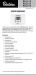
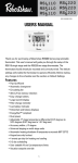
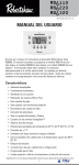
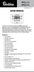
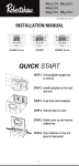
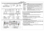
RS4110 RS4220 RS4320
RS5110 RS5220
RS6110 RS6220 RS6320
352-00060-001 Rev B
INSTALLATION MANUAL
RS4000 Series
RS5000 Series
RS6000 Series
QUICK START
STEP 1 Pull backplate straight out
to remove
STEP 2 Install backplate on the wall
and wire
STEP 3 Push front onto backplate
STEP 4 Remove tape on cover
STEP 5 Rotate cover up and remove
battery tray
STEP 6 Place batteries in tray and
place in thermostat
1
Thank you for purchasing a Robertshaw® thermostat. This manual will
describe how to install and test the Robertshaw single stage
thermostats RS4110, RS5110, RS6110, two stage RS4220, RS5220, RS6220,
and three stage* RS4320, RS6320 thermostats. For complete operation
instructions, refer to the Robertshaw User Manual.
Use the model number to identify your thermostat.
RSX110
Application
0 = Standard Thermostat
Number of Cooling Stages
Number of Heating Stages
4 = Non-Programmable
Value Series
5 = Programmable Value Series
with 5-2 Day Schedule
6 = Programmable Value Series
with 7 Day Schedule and
Copy Feature
These thermostats have three main parts:
A. The backplate – mounts to the wall and has wire connections.
B. The body – snaps to the backplate and contains the electronics and
programming buttons.
C. The cover – snaps to the top of the body and swings up to give
access to the programming buttons.
Recycling Thermostat
If this thermostat is replacing a thermostat that contains mercury in a
sealed tube, do not place your old thermostat in the garbage. Contact
your local waste management authority for instructions regarding
proper disposal of the thermostat. If you have any questions, call
Robertshaw technical support at 1-800-445-8299.
* Three stages of heating available for heat pump applications only.
2
IMPORTANT SAFETY INFORMATION
WARNING:
• Always turn off power at main fuse or circuit breaker panel before
installing, removing, cleaning, or servicing thermostat.
• Read all the information in this manual before installing this
thermostat.
• This is a 24V AC low-voltage thermostat. Do not install on voltages
higher than 30V AC.
• All wiring must conform to local and national building and electrical
codes and ordinances.
• This is a dual powered thermostat that will operate on 24V AC
or batteries.
• Do not short (jumper) across terminals on the gas valve or at the
system control to test installation. This will damage the thermostat
and void the warranty.
• Do not connect ground to any terminal in this unit.
• This thermostat is configured with automatic compressor protection
to prevent damage because of short cycling or extended power
outages. Short cycle protection provides a delay between
compressor cycles on heat pumps.
Replacing Existing Thermostat
1. Turn off power to heating and cooling system.
2. Remove cover from old thermostat to expose wires.
3. Disconnect wires one at a time from existing terminals. Use
enclosed labels to mark existing wires. Refer to cross references in
Table 1 if existing wiring does not directly match the labels.
4. Remove existing thermostat base from wall.
Table 1
Old Terminal
R, RH/R, V-VR or VR-R
RC
New Label
Description
R/RH
24V AC Return
RC
24V AC Cooling Transformer
C, X or B
C
24V AC Transformer Common Side
F or G
G
Fan Control Relay
Y, Y1 or M
Y1
1st Stage Cooling Circuit
W1 or W
W1
1st Stage Heating Circuit
Y2
Y2
2nd Stage Cooling Circuit
W2 or W-U
W2
2nd Stage Heating Control
W3
E
3rd Stage Heating Control
E
E
Emergency Heating Control
3
Installing the Robertshaw Thermostat Base
NOTE: For new installations, mount the thermostat on an inside wall, five
feet above the floor. Do not install behind a door, in a corner,
near air vents, in direct sunlight, or near any heat or steam
generating fixtures. Installation at these locations will affect
thermostat operation.
1. Be certain power is off to the heating and cooling systems.
2. Remove the backplate by placing your finger through the wire
opening. Pull the backplate straight out from the body.
3. Place the backplate in position on the wall. Pull the wires through
the wire opening.
4. Hold the backplate level and mark the mounting holes on the wall.
5. Drill the marked holes using a 5 mm (3/16 in.) drill bit.
6. Tap in the wall anchors and secure the base to the wall with the
supplied screws.
NOTE: The thermostats are designed to also mount on a single gang
junction box.
Wiring Terminals
Wire Opening
RH/R
G
RC
O
C
B
L
Y1
W1
Y2
W2
E
Mounting Holes
Providing Power to the Thermostat
To take advantage of the Pop-Up Wizard, power should be applied when
the settings are ready to be entered. Fill in the chart in the Pop-Up
Wizard section before applying power.
These thermostats will run on either two AA batteries or 24V AC. If the
common wire from the transformer is not available, the unit must be
powered by two AA batteries.
Thermostats with batteries and powered by 24V AC will continue to
function if the 24V AC fails.
Maintaining the Batteries
When the batteries are low, the thermostat will enter a
low power mode. Low battery mode has two levels.
• LEVEL 1: The low battery icon will be displayed.
• LEVEL 2: The low battery icon will flash indicating
that THE SYSTEM WILL NOT OPERATE.
4
System Switch Selection
The body of the thermostat has two switches on the backside. They are
accessible by removing the backplate from the body. The installer
should set these to match the system.
If the thermostat is controlling a heat pump system, set the first switch
to Heat Pump. Set the second switch based on the type of the backup
heating system.
If the thermostat is controlling a non-heat pump system, set the first
switch to Non-Heat Pump. The second switch must be set to match the
system as Gas or Electric.
If Non-Heat Pump and Gas are selected, the heating system will control
the fan.
If Non-Heat Pump and Electric are selected, the thermostat will control
the fan.
If Heat Pump is selected, the thermostat will control the fan.
Heat Pump or Non-Heat Pump
Heat
Pump
Non-Heat
Pump
Gas or Electric
Gas
Electric
Connecting the Wires
1. The wire ends should be stripped back 8 mm (5/16 in.).
2. Use the Wiring Diagrams and secure the wires into the terminal
strip. If replacing another thermostat, the wires should have been
labeled. Match the labels to the terminals. Tighten the screws.
3. Pull lightly on each wire to ensure the connection is secure.
NOTE: Nightlight feature is only enabled when the RH/R and C terminals
are connected.
5
Terminal Function
One Stage Models RS4110, RS5110 and RS6110
TERMINAL
EQUIPMENT TO
CONNECT
DESCRIPTION
C
24V AC
Common
Connection
For input of 24V AC common side of transformer.
Connect to 24V AC common side of the transformer for line power and nightlight feature.
RH/R
24V AC
Hot Connection
Connect to 24V AC hot side of the transformer.
RC
24V AC
Hot Connection
Connect to 24V AC hot side of the cooling
transformer for two transformer systems.
Note: Remove jumper to Rh when RC is connected.
Y1*
First stage
compressor
connection
Energizes on a call for first stage of cooling.
Energizes on a call for first stage of heating when
configured as a HP.
W1*
First stage
heat connection
Energizes on a call for first stage of heating when
configured as a Non-HP.
G
Indoor fan
connection
Energizes with Y1 and Y2.
Energizes with W1 and W2 if the Gas/Elec switch
is set to electric.
Energizes when fan is switched to ON.
O
Energizes for heat pump cool reversing valve.
B
Energizes for heat pump heat reversing valve.
* This thermostat can be used as a heat-only or cool-only thermostat. Therefore, it
is not always necessary to use both W1 and Y1.
Two Stage Models RS4220, RS5220 and RS6220
TERMINAL
EQUIPMENT TO
CONNECT
24V AC
Compressor Fault
Output
Second stage
cooling
connection.
L
Y2
DESCRIPTION
Connect to fault signal for input from
a compressor.
Energizes on a call for second stage
cooling (aux.).
W2
Second stage
heat connection
Energizes on a call for second stage
heating (aux.).
E
Emergency Heat
Connection
Energizes on a call for emergency heat.
Three Stage Models RS4320 and RS6320
TERMINAL
EQUIPMENT TO
CONNECT
DESCRIPTION
E
Third stage heat
Energizes on a call for 3rd stage heat
6
Wiring Diagrams
When used as
Heat Pump with Cool Active Reversing Valve With Battery
Transformer
Hot
120 Vac
24 Vac
Remove jumper if
separate cooling
transformer is
present.
Fan
Relay
Reversing
Valve
RH/R
RC
C
Not used
for RS4110,
RS5110 and
RS6110
G
O
B
Compressor
Fault Output
(24VAC)
L
Compressor
Contactor
Y1
W1
Second
Stage Cool
Second
Stage Heat
Emer Heat or
Third Stage Heat
Y2
W2
E
Not used
for RS4110,
RS5110 and
RS6110
Make certain the HP switch is in the HP position.
When used as
Heat Pump with Heat Active Reversing Valve With Battery
Transformer
Hot
120 Vac
24 Vac
Remove jumper if
separate cooling
transformer is
present.
Fan
Relay
RH/R
RC
Reversing
Valve
Compressor
Contactor
C
Not used
for RS4110,
RS5110 and
RS6110
G
O
Compressor
Fault Output
(24VAC)
L
B
Y1
W1
Second
Stage Cool
Second
Stage Heat
Emer Heat or
Third Stage Heat
Y2
W2
E
Not used
for RS4110,
RS5110 and
RS6110
Make certain the HP switch is in the HP position.
When used as
Non-Heat Pump With Battery
Heat
Transformer
Hot
120 Vac
24 Vac
Remove jumper if
separate cooling
transformer is
present.
Not used
for RS4110,
RS5110 and
RS6110
Fan
Relay
RH/R
RC
G
O
C
B
L
Cooling
Transformer
Compressor
Contactor
First Stage
Heat
Second
Stage Cool
Second
Stage Heat
Hot
120 Vac
24 Vac
Cooling transformer is not required
Make certain the HP switch is in the Non-HP position.
7
Y1
W1
Y2
W2
E
Not used
for RS4110,
RS5110 and
RS6110
Wiring Diagrams
When used as
Non-Heat Pump With Battery Backup
Transformer
Hot
120 Vac
24 Vac
Remove jumper if
separate cooling
transformer is
present.
Not used
for RS4110,
RS5110 and
RS6110
Fan
Relay
RH/R
RC
G
O
C
B
Compressor
Contactor
First Stage
Heat
Second
Stage Cool
Second
Stage Heat
L
Y1
W1
Y2
Not used
for RS4110,
RS5110 and
RS6110
W2
E
Make certain the HP switch is in the Non-HP position.
When used as
Heat Pump with Cool Active Reversing Valve With Battery Backup
Transformer
Hot
120 Vac
24 Vac
Remove jumper if
separate cooling
transformer is
present.
Fan
Relay
Reversing
Valve
RH/R
RC
G
O
C
Not used for
RS4110, RS5110
and RS6110
L
B
Compressor
Fault Output
(24VAC)
Compressor
Contactor
Y1
W1
Second
Stage Cool
Second
Stage Heat
Y2
W2
E
Emer Heat or
Third Stage Heat
Not used
for RS4110,
RS5110 and
RS6110
Make certain the HP switch is in the HP position.
When used as
Heat Pump with Heat Active Reversing Valve With Battery Backup
Transformer
24 Vac
Remove jumper if
separate cooling
transformer is
present.
Not used
for RS4110,
RS5110 and
RS6110
Hot
120 Vac
Fan
Relay
RH/R
RC
Reversing
Valve
Compressor
Contactor
C
L
G
O
Compressor
Fault Output
(24VAC)
B
Y1
W1
Second
Stage Cool
Second
Stage Heat
Emer Heat or
Third Stage Heat
Make certain the HP switch is in the HP position.
8
Y2
W2
E
Not used
for RS4110,
RS5110 and
RS6110
Applying Power
Before applying power, fill in the chart in the Pop-Up Wizard section of
this manual.
When 24V AC power or battery power is first applied to the thermostat,
the display will show the model number followed by the Pop-Up Wizard.
The thermostat will start normal operation following the Pop-Up Wizard.
Power is applied to the thermostat two ways:
1. Installing the batteries.
2. Not installing the batteries and connecting the thermostat body to a
backplate that has the C terminal connected and 24V AC present.
NOTE: A thermostat powered by 24V AC will use the batteries as backup
power if the 24V AC fails.
Installing Batteries
To remove the battery compartment
gently squeeze the ribbed edges on
both sides.
The battery compartment will pull
down from the thermostat body and
will detach. Install two AA batteries
following the polarity as shown
inside the compartment. Place
compartment back into the
thermostat.
Connecting The Body
Attach the thermostat body to the backplate by holding it directly in front
of the backplate. The edges will match and the wiring connections will
make contact. Push the body in until it snaps in place.
9
Pop-Up Wizard
The Wizard routine will display factory default settings. Each setting will
display for ten seconds. Use the
or
buttons to change the
setting. Settings that are not changed will operate with the values that
are displayed. To fast forward through the Wizard, press Edit Schedule.
The Wizard can be exited by pressing Start/Stop Schedule. This will
save the settings and place the thermostat into operation.
Use this chart to write down the desired settings before applying power.
Settings may vary by model.
Displayed
Details
SCAL
choose °F or °C
Default Change To
°F
CLOC
choose 12 or 24 hour
12
_______
LITE
y = always on, n = off
y
_______
DIFF
differential, set between 0.5 to 3.0 °F
or 0.5 to 1.5 °C
1 °F
_______
DIF2
2nd stage differential,
added to first stage differential
2 °F
_______
DLY2
2nd stage delay, in minutes
20
_______
DLY3
3rd stage delay, in minutes
20
_______
AUTO
auto changeover enable
y
_______
DEDB
auto changeover deadband
in degrees
3 °F
_______
HI
heat setting limit in degrees
90 °F
_______
LO
cool setting limit in degrees
45 °F
_______
VAC HEAT
vacation heat setpoint in degrees
62 °F
_______
85 °F
_______
_______
VAC COOL
vacation cool setpoint in degrees
CHECK
check filter timer in hours
CYCL
compressor short cycle delay in minutes
5
_______
CAL
calibration offset in degrees
0
_______
n or OFF
_______
After the Wizard has configured the thermostat, the settings can be
edited by pressing
and
simultaneously. This will allow you to
change settings.
Factory settings that have not been changed will use the default settings
for operation.
10
Default EnergyStar™ Settings for
RS5000 and RS6000
The RS5000 and RS6000 series are programmable thermostats and are
preprogrammed with a schedule that is recommended by EnergyStar™.
The schedule is designed to lower energy costs year-round.
EnergyStar™ Temperature Settings
Winter (Heating)
Summer (Cooling)
Morning (6:00 am)
70 °F (21 °C)
78 °F (25 °C)
Day (8:00 am)
62 °F (17 °C)
85 °F (29 °C)
Evening (6:00 pm)
70 °F (21 °C)
78 °F (25 °C)
Night (10:00 pm)
62 °F (17 °C)
82 °F (28 °C)
Setting Time and Day for the RS5000 and
RS6000 Series
To adjust the time and day settings press the SET TIME button. The hour
will flash. To change the settings:
1. Use the
and
buttons to change the flashing number.
2. Press the SET TIME button to move through hours, minutes and days
of week.
3. Make changes as needed. They will be saved automatically.
NOTE: The thermostat will not correct for Daylight Saving Time.
Installation Test Utility
WARNING: The installation test procedures
can damage the heating/cooling equipment
if used incorrectly. These procedures
should only be performed by trained
HVAC personnel.
The following instructions may be used to test the heating/cooling
system for correct function.
To enter the test mode press and hold
and
for five seconds.
Short Cycle protection is disabled when using the test utility.
Push the
test mode.
and
or Start/Stop schedule buttons at any time to exit
In the test mode:
Press
to force the fan on or off.
Pressing
repeatedly will allow testing of the system modes. See
following tables. The display will show appropriate animated icons.
11
Press
to step through the following:
Installation Tests for Single Stage Models
Conventional (Non-HP)
Demand
Terminal
First Stage Heat
W1 + G*
Y1 + G
First Stage Cool
Y1 + G
Y1 + G + O
* G,
Display
Heat Pump (HP)
Terminal
Display
will be off (not displayed) for Non-HP with Gas.
Installation Tests for Multi-Stage Models
Conventional (Non-HP)
Demand
Terminal
First Stage Heat
W1 + G*
Display
Y1 + G
Second Stage
Cool
Y1 + Y2 + G
* G,
Terminal
Display
Y1 + G + B
Second Stage
W1 + W2 + G*
Heat
Third Stage /
N/A
Emergency Heat
First Stage Cool
Heat Pump (HP)
2
Y1 + W2 +G + B
E+G
2
E
Y1 + G + O
Y1 + Y2 + G + O 2
2
will be off (not displayed) for Non-HP with Gas
The display will now show the day, the
setpoint, fan setting and off.
Exiting the Installation Test Utility returns the
thermostat to normal operation.
Refer to the User Manual to change day, time and schedule.
The Thermostat is now ready to begin operation.
The thermostat will be in the OFF (default) mode at start up.
The following sections will explain how to select the mode of operation
and how to protect the settings.
12
Setting the Mode
Press the
button to cycle through the available modes.
Off
OFF
Heat
Cool
Emergency Heat
(Multi-Stage Heat Pump units)
E
Auto changeover (if enabled)
A
Setting Mode to Emergency Heat
The multi-stage thermostats have have an emergency heat capability for
heat pump systems.
An E will be displayed with the heat symbol . Use emergency heat to
turn off the heat pump and turn on a secondary heating source. This
mode is used to bypass the heat pump when it needs servicing or when
it cannot keep up with the heat demand.
Setting Mode to Auto Changeover
When auto changeover is active the letter A is displayed next to the
and
.
Changing from heat-to-cool or cool-to-heat is automatic. As the room
temperature changes, the thermostat will call for heating or cooling as
needed. The display will flash the heat
which system is active.
or cool
symbol to show
Note that the Hi/Low temperature limits are not enforced in auto
changeover mode. Auto changeover mode can be disabled as a user
option in the pop-up wizard.
Security Lockout to Protect the Settings
The buttons on the front of the thermostat can be locked with a password.
To create a password:
1. Press the
and
buttons at the same time and hold them in
for 5 seconds.
You will be asked for a 4 digit password (the RS4000 series
thermostats use 2 digits).
2. Each digit is set using the
and
move to the next digit. Press
buttons. Press the
to
to move back.
3. The password is saved after 5 seconds.
All the front buttons are now locked out until the password is entered.
Pressing any button will cause
to flash.
13
To unlock the buttons:
1. Push and hold the
and
buttons for 5 seconds until the
request for password is displayed.
2. Enter the digits for the password by pressing the
buttons. Press the
move back.
and
to move to the next digit. Press
to
3. When the correct password is set, wait for 5 seconds to unlock
the system.
4. If the wrong password is entered the display will flash -- for 5
seconds then return to normal.
Once the security has been disabled, a password needs to be
re-created to protect the settings.
Thermostat Specifications
Operating Voltage
18-30V AC
Maximum Load Current
1 Amp Max per Output Terminal
4 Amp Total Load
Output Type
Latching Relays
Batteries
2 AA Alkaline in Series
Battery Life
2 Years Typical
Ambient Operating Temperature
14 °F (-10 °C) to 122 °F (50 °C)
Storage Temperature
-4 °F (-20 °C) to 140 °F (60 °C)
Operational Mode Chart:
Demand
First Stage Heat
Second Stage Heat
Conventional
(Non-HP)
Heat Pump
(HP) Elec
Heat Pump
(HP) Gas
W1 + G*
Y1 + G + B
Y1 + G + B
W1 + W2 + G*
Y1 + Y2 + G + B Y1 + Y2 + G + B
or
or
Y1 + W2 + G + B Y1 + W2 + G + B
Y1 + Y2 + E +
G+B
Third Stage Heat
N/A
or
E+B
Y1 + W2 + E +
G+B
Emergency Heat
N/A
Y1 + G + O
Y1 + G + O
First Stage Cool
Y1 + G
Y1 + Y2 + G + O
Y1 + Y2 + G + O
Y1 + Y2 + G
E+G
E
Second Stage Cool
* G: G is off for Gas, on for Elec
14
Troubleshooting
Problem
Action
Thermostat does not turn on
system.
Check wiring
(see Wiring Diagrams section).
System turns on too often.
Increase temperature differential
(see Pop-Up Wizard section).
System fan does not operate
properly.
Move fan option switch to either
gas or electric, to match system
(see System Switch Selection
section).
Thermostat does not display
proper room temperature.
Check F/C (Fahrenheit/Celsius)
setting (see Pop-Up Wizard
section).
Display shows HI or LO and room
temperature is normal.
Call a licensed service person to
replace thermostat.
If problems with thermostat cannot be resolved, contact:
www.invensyscontrols.com
or
Technical Support: (800) 445-8299
Monday-Friday 7:30 AM - 5:30 PM CST
15
Five Year Limited Warranty
Invensys Controls warrants to the original contractor installer, or to the
original consumer user, each new Robertshaw thermostat to be free
from defects in materials and workmanship under normal use and
service for a period of five (5) years from date of purchase. This
warranty and our liability does not apply to batteries or merchandise
that has been damaged by misuse, neglect, mishandling, alterations,
improper installation, or use in a way other than in accordance with
Invensys Controls recommendations and instructions.
Invensys Controls agrees to repair or replace at its option any
thermostat under warranty provided it is returned within the warranty
period, postage prepaid, with proof of the date of purchase. Cost of
thermostat removal or reinstallation is not the responsibility of
Invensys Controls.
Repair or replacement as provided under this warranty is the exclusive
remedy of the consumer. Invensys Controls shall not be liable for any
incidental or consequential damages for breach of any express or
implied warranty on this product, or under any other theory of liability.
Except to the extent prohibited by applicable law, any implied warranty
of merchantability or fitness for a particular purpose on this product is
limited to the duration of this warranty.
Some states do not allow the exclusion or limitation of incidental or
consequential damages, or allow limitations on how long an implied
warranty lasts, so the above limitations or exclusions may not apply to
you. This warranty gives you specific legal rights, and you may also
have other rights which vary from state to state.
For warranty returns, send thermostat, shipping prepaid to:
Invensys Controls
Warranty Claims Department
515 S. Promenade
Corona, CA 91719
In Canada:
Invensys Controls
3505 Laird Road Unit #14
Mississauga, Ontario L5L 5Y7 Canada
Attn: Warranty Department
515 South Promenade Avenue
Corona, CA 92879-1736
United States of America
www.invensyscontrols.com
©2008 Invensys Controls 2/08
352-00060-001 Rev B
16
RS4110 RS4220 RS4320
RS5110 RS5220
RS6110 RS6220 RS6320
352-00060-001 Rev B
INSTALLATION MANUAL
RS4000 Serie
RS5000 Serie
RS6000 Serie
COMIENZO RÁPIDO
PASO 1 Para retirar la placa
posterior tire directamente
hacia afuera.
PASO 2 Instale la placa posterior
sobre la pared y realice
las conexiones.
PASO 3 Presione el frente contra la
placa posterior.
PASO 4 Retire la cinta de la tapa.
PASO 5 Gire la tapa hacia arriba
y retire la bandeja de
la batería.
PASO 6 Coloque las baterías en la
bandeja e instale la bandeja
en el termostato.
1
Gracias por comprar un termostato Robertshaw®. Este manual contiene
indicaciones para instalar y probar los termostatos Robertshaw de una
sola etapa RS4110, RS5110, RS6110, de dos etapas RS4220, RS5220,
RS6220, y de tres etapas* RS4320, RS6320. Para ver las instrucciones
completas consulte el Manual del Usuario Robertshaw.
Use el número de modelo que figura a continuación para identificar
su termostato.
RSX110
Aplicación
0 = Thermostato estándar
Cantidad de etapas de refrigeración
Cantidat de etapas de calefacción
4 = Serie Value no programable
5 = Serie Value programable
para 5 - 2 días
6 = Serie Value programable
para 7 días y función
de copiado
Estos termostatos tienen tres partes principales:
A. La placa posterior – se fija a la pared y contiene el cableado para
las conexiones.
B. El cuerpo – se encaja en la placa posterior y contiene los
componentes electrónicos y las teclas de programación.
C. La tapa – se encaja en la parte de superior del cuerpo y se remueve
para permitir el acceso a las teclas de programación.
Reciclado de termostatos
Si instala este termostato para reemplazar un termostato que contiene
mercurio en un tubo sellado, no deseche la unidad que reemplaza
arrojándola a la basura. Contacte a la autoridad local encargada de la
disposición de desechos y pida instrucciones para desechar
correctamente su termostato. Si tiene alguna pregunta, comuníquese
con el servicio técnico de Robertshaw llamando al 1-800-445-8299.
* Calefacción de tres etapas disponible solamente para aplicaciones de bomba de calor.
2
ADVERTENCIAS IMPORTANTES SOBRE
SEGURIDAD:
• Interrumpa siempre el suministro de electricidad desde la llave
principal o desde el panel del disyuntor antes de instalar, retirar,
limpiar o reparar el termostato.
• Lea toda la información que aparece en este manual antes de
instalar el termostato.
• Este es un termostato de bajo voltaje 24V CA. No instale con voltaje
superior a 30V CA.
• Todas las conexiones de cableado deben cumplir con las normas y
disposiciones locales y nacionales que rigen en materia de
construcción y electricidad.
• Este termostato funciona con energía suministrada por corriente de
24V CA o a pila.
• No deben puentearse los terminales de la válvula de gas ni el
control del sistema para probar la instalación. Esa práctica
perjudicará el termostato y causará la nulidad de la garantía.
• No conecte a tierra ninguno de los terminales de esta unidad.
• Este termostato está configurado con protección automática del
compresor para prevenir daños por ciclos de corta duración o
cortes prolongados de suministro de energía. La protección de
ciclos de corta duración proporciona un retardo en los ciclos del
compresor en las bombas de calor.
Para cambiar el termostato actual
1. Interrumpa el suministro de energía que llega a los sistemas de
calefacción y refrigeración.
2. Retire la tapa del viejo termostato para dejar expuestos los cables.
3. Desconecte los cables de a uno por vez de los terminales a los que
están conectados. Utilice los rótulos que se adjuntan para marcar
los terminales existentes. Consulte las referencias del Cuadro 1 si
los cables que están instalados no coinciden exactamente con
los rótulos.
4. Retire de la pared la base del viejo termostato.
Cuadro 1
R, RH/R, V-VR o VR-R
RC
R/RH
Retorno 24V CA
RC
Transformador del sistema de
refrigeración 24V CA
C, X o B
C
Lado común del transformador 24V CA
FoG
G
Relé de control del ventilador
Y, Y1 o M
Y1
Circuito de refrigeración 1ª Etapa
W1 o W
W1
Circuito de calefacción 1ª Etapa
Y2
Y2
Circuito de refrigeración 2ª Etapa
W2 o W-U
W2
Circuito de calefacción 2ª Etapa
W3
E
Circuito de calefacción 3ro Etapa
E
E
Control de calefacción de
emergencia
3
Instalación de la base del termostato
Robertshaw
NOTA: En instalaciones nuevas, coloque el termostato en una pared
interior, cinco pies por encima del piso. No instale detrás de
puertas, en rincones, cerca de corrientes de aire, a la luz directa
del sol o cerca de dispositivos que generen calor o vapor. La
instalación en esos sitios afectará el funcionamiento del
termostato.
1. Verifique que la corriente eléctrica esté desconectada de los
sistemas de calefacción y refrigeración.
2. Retire la placa posterior insertando el dedo a través del orificio de
los cables. Jale la placa posterior en forma horizontal para sacarla
del cuerpo.
3. Ubique la placa posterior sobre la pared. Jale de los cables y
sáquelos a través del orificio de los cables.
4. Mantenga la placa posterior nivelada y marque sobre la pared la
ubicación de los orificios de montaje.
5. Realice las perforaciones en los lugares marcados usando una
broca para taladro de 5 mm (3/16 in).
6. Golpee los insertos de fijación y fije la base a la pared con los
tornillos provistos.
NOTA: Los termostatos están diseñados para ser montados en una caja
individual de coneciones.
Terminales de cableado
Orificios para cables
RH/R
G
RC
O
C
B
L
Y1
W1
Y2
W2
E
Orificios de montaje
Para llevar energía al termostato
Para aprovechar las ventajas del asistente Pop-Up Wizard, el termostato
se debe energizar cuando se hayan determinado los valores y estén
listos para ser ingresados. Complete la tabla de la sección Pop-Up
Wizard antes de conectar la energía.
Estos termostatos funcionan con dos pilas AA o con corriente de 24V
CA. Si el cable común del transformador no está disponible, se debe
proporcionar enegía con dos pilas AA.
Los termostatos que funcionan con pilas y energía de 24V CA seguirán
funcionando si hay un corte de la corriente de 24V CA.
4
Mantenimiento de las pilas
Cuando las pilas están bajas, el termostato empieza a funcionar en
modo baja energía. El modo pila baja tiene dos niveles.
• NIVEL 1: Aparece en el visor el ícono de pila baja.
• NIVEL 2: Titila intermitentemente el ícono de pila
baja que indica que NO FUNCIONARÁ EL
SISTEMA.
Para elegir la posición de las llaves del sistema
El cuerpo del termostato tiene dos llaves en la parte posterior. Puede
acceder a ellas retirando del cuerpo la placa posterior. El instalador
debe elegir la posición adecuada para el sistema.
Si el termostato controla un sistema de bomba de calor, coloque la
primera llave en la posición “Heat Pump”(bomba de calor). El segundo
interruptor basado en el tipo de sistema de calefacción de respaldo.
Si el termostato contola un sistema de bomba no de calor, coloque la
primera llave en la posición “Non-Heat Pump” (sin bomba de calor). La
segunda llave se debe ubicar para que coincida con un sistema
alimentado a gas (boton en posición “Gas”) o electricidad (boton en
posición “Electric”).
Si elige “Non-Heat Pump” y “Gas”, el sistema de calefacción controlará
el ventilador.
Si elige “Non-Heat Pump” y “Electric”, el termostato controlará el
ventilador.
Si se selecciona Heat Pump (Bomba de calor) el termostato controlará
al ventilador.
Heat Pump o Non-Heat Pump
Gas o Electric
Conexión de los cables
1. Se debe desforrar 8 mm (5/16 in) del extremo de cada cable.
2. Use el Diagrama de cableado para asegurarse de que los cables
estén unidos al terminal que corresponde. Si está reemplazando un
termostato anterior, es necesario que haya rotulado los cables.
Haga coincidir los rótulos con los terminales. Ajuste los tornillos.
3. Jale suavemente de cada cable para verificar si la conexión está
asegurada.
NOTA: La iluminación nocturna sólo está habilitada cuando los
terminales RH/R y C están conectados.
5
Función del Terminal
Modelos de una etapa RS4110, RS5110 y RS6110
TERMINAL
EQUIPO AL QUE SE
CONECTA
C
Conexión común
24VCA
RH/R
Conexión 24V
CA vivo
Conecte al lado vivo del transformador de 24V CA.
RC
Conexión 24V
CA vivo
Conecte al lado vivo del transformador de
refrigeración de 24 V CA en el caso de sistemas
con dos transformadores.
Nota: Quite el puente a Rh cuando se conecta RC.
DESCRIPCIÓN
Para entrada de lado común del transformador
de 24V CA. Para alimentar desde la línea de
distribución de energía eléctrica y tener la
característica de luz nocturna conecte al lado
común del transformador de 24V CA.
Conexión
Energiza cuando se requiere primera etapa de
compresor primera refrigeración. Energiza cuando se requiere primera
etapa de calefacción cuando se configura como HP.
etapa
Y1*
Conexión calefacción Energiza cuando se requiere primera etapa de
calefacción cuando se configura como Non-HP.
primera etapa
W1*
Conexión
ventilador
interiores
G
Energiza con Y1 y Y2.
Energiza con W1 y W2 si la llave Gas/Elec se
coloca en electricidad.
Energiza cuando el ventilador se pone en ON.
Energiza válvula inversora de refrigeración de
bomba de calor.
Energiza válvula inversora de calefacción de
bomba de calor.
O
B
* Este termostato se puede usar como termostato de calefacción solamente o como termostado de refrigeración solamente. Por tanto, no siempre es necesario usar W1 y Y1.
Modelos de dos etapas RS4220, RS5220 y RS6220
TERMINAL
L
Y2
W2
E
EQUIPO AL QUE SE
CONECTA
24V CA
Falla de compresor
Salida
Conexión de
refrigeración de
segunda etapa
Conexión de
calefacción de
segunda etapa
Conección de
calefacción de
emergencia
DESCRIPCIÓN
Conecte la señal de falla para tener entrada
desde un compresor.
Energiza cuando se requiere segunda etapa de
refrigeración (aux).
Energiza cuando se requiere segunda etapa de
calefacción (aux).
Energiza cuando se requiere calefacción de
emergencia.
Modelos de dos etapas RS4320 y RS6320
TERMINAL
EQUIPO AL QUE SE
CONECTA
E
Calefacción de
tercera etapa
DESCRIPCIÓN
Se energiza por pedido de la calefacción de la
3ra etapa.
6
Diagrama de conexiones
Cuando se usa como bomba de calor con válvula
inversora activada en modo refrigeración con pilas
Transformador
Vivo
120 Vac
24 Vac
Retire el puente si hay un
transformador separado
para refrigeración
No se usa en los
modelos RS4110,
RS5110 y RS6110
RH/R
Relé del
ventilador
G
RC
Válvula
inversora
O
Contactor del
compresor
Y1
C
L
B
Salida falla
compresor
(24VCA)
W1
Refrigeración
segunda etapa
Verifique que la llave HP esté en la posición "HP".
Calefacción
segunda etapa
Calefacción de
Emergencia
o Calefacción de
Tercera Etapa
Y2
W2
No se usa en los
modelos RS4110,
RS5110 y RS6110
E
Cuando se usa como bomba de calor con válvula
inversora activada en modo calefacción con pilas
Transformador
Vivo
120 Vac
24 Vac
Retire el puente si hay un
transformador separado
para refrigeración
No se usa en los
modelos RS4110,
RS5110 y RS6110
Relé del
ventilador
RH/R
RC
Válvula
inversora
C
L
G
O
Salida falla
compresor
(24VCA)
Contactor del
compresor
B
Y1
W1
Verifique que la llave HP esté en la posición "HP".
Refrigeración
segunda etapa
Y2
Calefacción
segunda etapa
W2
Calefacción de
Emergencia
o Calefacción de
Tercera Etapa
No se usa en los
modelos RS4110,
RS5110 y RS6110
E
Cuando se usa como bomba
no de calor con pilas
Transformador
de calefacción
Vivo
120 Vac
24 Vac
Retire el puente si hay un
transformador separado
para refrigeración
No se usa en los
modelos RS4110,
RS5110 y RS6110
Relé del
ventilador
RH/R
RC
G
O
C
B
L
Transformador
de refrigeración
Contactor del
compresor
Y1
Calefacción de
primera etapa
W1
Refrigeración de
segunda etapa
Y2
Calefacción de
segunda etapa
W2
Vivo
120 Vac
24 Vac
No se necesita transformador de refrigeración
Verifique que la llave HP esté en la posición "Non-HP".
7
E
No se usa en los
modelos RS4110,
RS5110 y RS6110
Diagrama de conexiones
Cuando se usa como bomba de
no calor con respaldo de pilas
Transformador
Vivo
120 Vac
24 Vac
Retire el puente si hay un
transformador separado
para refrigeración
Relé del
ventilador
RH/R
RC
No se usa en los
modelos RS4110,
RS5110 y RS6110
G
O
C
B
L
Contactor
del compresor
Y1
Calefacción de
primera etapa
W1
Refrigeración de
segunda etapa
Y2
Calefacción de
segunda etapa
W2
No se usa en los
modelos RS4110,
RS5110 y RS6110
E
Verifique que la llave HP esté en la posición "Non-HP".
Cuando se usa como bomba de calor con válvula
inversora activada en modo refrigeración con respaldo de pilas
Transformador
24 Vac
Retire el puente si hay un
transformador separado
para refrigeración
Vivo
120 Vac
RH/R
Relé del
ventilador
G
RC
Válvula
inversora
O
Contactor del
compresor
Y1
C
No se usa en los
modelos RS4110,
RS5110 y RS6110
L
B
Salida falla
compresor
(24VCA)
W1
Refrigeración
segunda etapa
Calefacción
segunda etapa
Verifique que la llave HP esté en la posición "HP".
Calefacción de
Emergencia
o Calefacción de
Tercera Etapa
Y2
W2
No se usa en los
modelos RS4110,
RS5110 y RS6110
E
Cuando se usa como bomba de calor con válvula inversora
activada en modo calefacción con respaldo de pilas
Transformador
Vivo
120 Vac
24 Vac
Retire el puente si hay un
transformador separado
para refrigeración
Relé del
ventilador
RH/R
RC
No se usa en los
modelos RS4110,
RS5110 y RS6110
Válvula
inversora
C
L
G
O
Salida falla
compresor
(24VCA)
Contactor del
compresor
B
Y1
W1
Verifique que la llave HP esté en la posición "HP".
8
Refrigeración
segunda etapa
Y2
Calefacción
segunda etapa
W2
Calefacción de
Emergencia
o Calefacción de
Tercera Etapa
E
No se usa en los
modelos RS4110,
RS5110 y RS6110
Para conectar a la fuente de energía
Antes de conectar a la fuente de energía, complete la tabla de la
sección Pop-Up Wizard de este manual.
Cuando el termostato se conecta por primera vez con la corriente 24V
CA o se colocan las pilas, el visor mostrará el número de modelo y luego
aparecerá la pantalla del asistente Pop-Up Wizard. El termostato
empezará a funcionar normalmente después de la presentación de la
pantalla Pop-Up Wizard. Para conectar a la fuente de energía se puede
proceder de dos maneras.
1. Colocando las pilas.
2. Sin las pilas, conectando el cuerpo del termostato a la placa
posterior que tiene el terminal C conectado, la unidad recibirá
corriente 24V CA.
NOTA: El termostato conectado a la corriente 24V CA usará las pilas
como respaldo en caso de corte de suministro de la energía de
24V CA.
Para colocar las pilas
Para retirar el compartimiento de las
pilas, apriete suavemente los bordes
estriados de ambos lados.
El compartimiento de pilas se
desprenderá del cuerpo del
termostato. Coloque dos pilas AA
según la indicación de polaridad que
figura en el interior del
compartimiento. Vuelva a colocar en el termostato.
Para conectar el cuerpo
Fije el cuerpo del termostato a la placa posterior sosteniendo
directamente frente a la placa. Los bordes coincidirán y las conexiones
harán contacto. Empuje el cuerpo hacia atrás hasta que encaje
firmemente.
9
Pop-Up Wizard
La rutina de la pantalla Wizard mostrará los ajustes que vienen de
fábrica por defecto. Cada ajuste aparecerá diez segundos. Use las
teclas
o
para cambiar los ajustes ingresados. Los ajustes que no
se modifiquen funcionarán con los valores mostrados. Para avanzar
rápido por la pantalla Wizard, pulse la tecla “Edit Schedule” (editar
programa”. Puede salir del asistente Wizard pulsando la tecla
“Start/Stop Schedule” (iniciar/detener programa). De esta forma se
guardarán los ajustes introducidos y el termostato empezará a
funcionar.
Use esta tabla para registrar los ajustes preferidos antes de conectar
con la fuente de energía. Los ajustes dependen del modelo.
Visor
Detalles
Valor por defecto Cambiar a
SCAL
elegir °F o °C
°F
_______
CLOC
elegir 12 ó 24 horas
12
_______
LITE
y = siempre prendido, n = apagado
y
_______
DIFF
diferencial, fijar entre 0.5 y 3.0 °F ó 0.5 y 1.5 °C
1 °F
_______
DIF2
diferencial 2ª etapa, sumado al
diferencial de primera etapa
2 °F
_______
DLY2
retardo 2ª etapa, en minutos
20
_______
DLY3
retardo 3ro etapa, en minutos
20
_______
AUTO
auto changeover enable
y
_______
DEDB
margen de oscilación para conmutación
automática, en grados
3 °F
_______
HI
límite ajuste calefacción, en grados
90 °F
_______
LO
límite ajuste refrigeración, en grados
45 °F
_______
VAC HEAT
valor deseado calefacción en
vacaciones, en grados
62 °F
_______
VAC COOL valor deseado refrigeración en
vacaciones, en grados
85 °F
_______
CHECK
controla el temporizador del filtro, en horas
n o OFF
_______
CYCL
retardo ciclo corto compresor, en mintuos
5
_______
CAL
compensación de calibración en grados
0
_______
Después de configurar la pantalla del asistente Wizard Pop-Up, usted
puede editar los ajustes pulsando las teclas
y
simultáneamente.
De esta forma, podrá modificar los valores fijados.
Los ajustes de fábrica que no se hayan modificado funcionarán con los
ajustes por defecto.
10
Ajustes por defecto EnergyStar™ de los modelos RS5000 y RS6000
Las series RS5000 y RS6000 son termostatos programables y están
preparados de fábrica con un programa que es recomendado por
EnergyStar™. El programa está diseñado para ahorrar energía
todo el año.
Ajustes de temperatura EnergyStar™
Invierno (Calefacción) Verano (Refrigeración)
Mañana (6:00 am)
70 °F (21 °C)
78 °F (25 °C)
Día (8:00 am)
62 °F (17 °C)
85 °F (29 °C)
Anochecer (6:00 pm)
70 °F (21 °C)
78 °F (25 °C)
Noche (10:00 pm)
62 °F (17 °C)
82 °F (28 °C)
Cómo ajustar la ahora y el día en las series
RS5000 y RS6000
Para ajustar la hora y el día, pulse la tecla SET TIME (fijar la hora). La
hora titilará en forma intermitente. Para cambiar los ajustes:
1. Use las teclas
y
para modificar los números que titilan.
2. Pulse la tecla SET TIME (fijar la hora) para avanzar las horas,
minutos y días de la semana.
3. Realice los cambios necesarios. Se guardarán automáticamente.
NOTA: El termostato no se ajustará automáticamente durante el período
de ahorro de luz de día.
Prueba de instalación
ADVERTENCIA: La prueba de instalación
puede dañar el equipo si se realiza
incorrectamente. El procedimiento deben
estar a cargo de personal idóneo en
servicios de HVAC.
Puede usar las siguientes instrucciones para probar el correcto
funcionamiento del sistema de calefacción/refrigeración.
Para ingresar el modo prueba, pulse y mantenga oprimida las teclas
y
durante cince segundos
La protección de ciclo corto queda desactivada mientras se realiza
la prueba.
Pulse
y
o las teclas de programación Start / Stop en cualquier
momento para salir del modo ensayo (test).
En el modo prueba:
Pulse la tecla
para forzar el encendido o apagado del ventilador. El
ícono del ventilador rotará.
11
Si pulsa las teclas
repetidamente podrá realizar las pruebas de los
modos del sistema. Ver los cuadros siguientes. El visor mostrará los
íconos animados correspondientes.
Pulse
para recorrer lo siguiente:
Pruebas de Instalación para Modelos de Una sola Etapa
Convencional (No-HP)
Bomba de calor (HP)
Demanda
Terminal
Terminal
Calefacción
primera etapa
Calefacción
primera etapa
W1 + G*
Y1 + G
Y1 + G
Y1 + G + O
* G,
Visor
Visor
estarán apagados (no aparecerán) en No-HP/ Gas.
Pruebas de Instalación para Modelos de Etapas Múltiples
Convencional (No-HP)
Demanda
Calefacción
primera etapa
Calefacción
segunda etapa
Tercera etapa /
Calefacción de
emergencia
Refrigeración
primera etapa
Refrigeración
segunda etapa
* G,
Terminal
Visor
W1 + G*
Terminal
Visor
Y1 + G + B
W1 + W2 + G*
2
N/A
Y1 + W2 +G + B
E+G
Y1 + G
Y1 + Y2 + G
Bomba de calor (HP)
2
E
Y1 + G + O
2
Y1 + Y2 + G + O 2
estarán apagados (no aparecerán) en No-HP/ Gas
El visor mostrará ahora el día, el punto de
ajuste, el ajuste del ventilador On y OFF.
Al salir de Prueba de Instalación el
termostato retorna a la operación normal.
Consulte el Manual del Usuario para cambiar el día, la hora y el
programa.
El termostato ahora está listo para empezar a funcionar.
El termostato estará en OFF (apagado) por defecto como modo de inicio.
En las siguientes secciones se explica cómo elegir el modo de
funcionamiento y cómo proteger los valores de ajuste.
12
Para ajustar el modo
Pulse la tecla
para pasar por todos los modos posibles.
Off (apagado)
OFF
Heat (calefacción)
Cool (refrigeración)
Emergency Heat
(Calefacción de emergencia)
(Unidades con Bombas de
Calor de Etapas Múltiples)
E
Auto changeover (if enabled)
(conmutación automática
(si están activadas)
A
Para fijar el modo calefacción de emergencia
Los termostatos de etapas múltiples tienen una característica de
calefacción de emergencia para los sistemas de bomba de calor.
Aparecerá una “E” con el símbolo de calefacción . Use la calefacción
de emergencia para apagar la bomba de calor y prender una fuente
secundaria de calefacción. Este modo se usa para hacer un bypass a la
bomba de calor cuando ésta necesita reparación o cuando no puede
dar abasto con la demanda de calefacción.
Para fijar el modo conmutación automática
Cuando la función conmutación automática está activada, aparece la
letra A en el visor junto a los íconos
y
.
El pasaje de calefacción a refrigeración o viceversa es automático.
Conforme varía la temperatura ambiente, el termostato funciona
calefaccionando o refrigerando, según las necesidades. El ícono de
calefacción o el de refrigeración
qué sistema es el que está activo.
estará iluminado para indicar
Nótese que los límites de temperatura Hi / Low no son respetados en el
modo conmutación automática. El modo conmutación automática
puede ser desactivado como opción del usuario en el genio pop-up.
Bloqueo de seguridad para proteger los ajustes
Las teclas de la parte anterior del termostato se pueden bloquear con
una contraseña. Para crear una contraseña:
1. Pulse las teclas
y
al mismo tiempo y manténgalas
oprimidas durante 5 segundos.
El sistema le pedirá una contraseña de 4 dígitos (el termostato de la
serie RS4000 utiliza 2 dígitos).
2. Cada dígito se fija con las teclas
para pasar al dígito siguiente. Pulse
y
. Pulse las teclas
para ir hacia atrás.
3. La contraseña se guarda después de 5 segundos.
13
Todas las teclas de la parte anterior ahora están bloqueadas y
permanecerán bloqueadas hasta que se ingresa la contraseña.
Si pulsa cualquier tecla aparecerá el ícono
.
Para destrabar las teclas:
1. Pulse y mantenga oprimidas las teclas
y
durante 5
segundos hasta que el sistema le solicite la contraseña.
2. Ingrse los dígitos de la contraseña pulsando las teclas
Pulse las teclas
y
.
para pasar al dígito siguiente. Pulse la tecla
para ir hacia atrás.
3. Cuando se ha logrado la correcta con trasera, espere 5 segundos
para desbloquear el sistema.
4. Si ingresa la contraseña equivocada, en el visor titilará la palabra
“--” durante 5 segundos y luego volverá a la pantalla normal.
Una vez que ha desactivado la protección de seguridad, deberá volver a
crear otra contraseña para proteger los ajustes ingresados.
Especificaciones del termostato
Voltaje de funcionamiento
18-30 VAC
Carga máxima de corriente
1 amp máx por terminal de salida
Carga total 4 amp
Tipo de salida
Relé de traba
Pilas
2 pilas alcalinas AA en series
Vida útil de las pilas
2 años promedio
Temperatura ambiente de funcionamiento 14 °F (-10 °C) a 122 °F (50 °C)
Temperatura de depósito
-4 °F (-20 °C) a 140 °F (60 °C)
14
Cuadro del Modo Operacional:
Convencional Bomba de calor Bomba de calor
(Non-HP)
(HP) Elec
(HP) Gas
Demanda
Primera etapa
de calefacción
W1 + G*
Segunda etapa
de calefacción
W1 + W2 + G*
Y1 + G + B
Y1 + G + B
Y1 + Y2 + G + B Y1 + Y2 + G + B
or
or
Y1 + W2 + G + B Y1 + W2 + G + B
Y1 + Y2 + E +
G+B
Tercera etapa
de calefacción
N/C
E+B
or
Y1 + W2 + E +
G+B
Calefacción de
emergencia
Primera etapa
de refrigeración
Segunda etapa
de refrigeración
N/C
Y1 + G + O
Y1 + G + O
Y1 + G
Y1 + Y2 + G + O
Y1 + Y2 + G + O
Y1 + Y2 + G
E+G
E
* G: G está en off para Gas, on para Elec
Resolución de problemas
Problema
Solución
El termostato no pone en
funcionamiento el sistema.
Verifique el cableado
(ver sección Diagramas de
cableado).
El sistema se pone en
funcionamiento muy pronto.
Aumente el diferencial de
temperatura
(ver sección Pop-Up Wizard).
El ventilador no funciona
correctamente.
Cambie la opción del ventilador a
gas o electricidad para adecuarlo
al sistema (ver sección Para
elegir la posición de las llaves
del sistema).
El termostato no muestra la
temperatura ambiente correcta.
Verifique el ajuste de la escala F/C
(Fahrenheit/Celsius) (ver sección
Pop-Up Wizard).
El visor muestra HI o LO y la
temperatura ambiente es normal.
Para reemplazar el termostato
recurra a un técnico calificado.
Si no puede resolver algún problema con su termostato, póngase en
contacto con:
www.invensyscontrols.com
o
Soporte Técnico: (800) 445-8299
De lunes a viernes de 7:30 AM a 5:30 PM CST
15
GARANTIA LIMITADA DE 5 AÑOS
Invensys Controls garantiza al instalador contratista original o al usuario
original que cada termostato Robertshaw nuevo no tendrá defectos en
componentes ni en construcción con el uso y mantenimiento normal
durante un período de cinco (5) años desde la fecha de la compra. Esta
garantía y nuestra responsabilidad no se aplican a las pilas ni a los
productos que hayan sido dañados por maltrato, negligencia, falta de
cuidado en el manejo, modificaciones, instalación incorrecta o uso que
no se condiga con las recomendaciones e instrucciones de Invensys
Controls.
Invensys Controls acepta reparar o cambiar, según su criterio, todo
termostato en garantía siempre y cuando sea devuelto dentro del
período de garantía, con franqueo prepago con prueba de fecha de
compra. El costo del retiro o reinstalación del termostato no serán
responsabilidad de Invensys Controls.
La reparación o el remplazo previstos en la garantía constituyen el único
recurso del consumidor. Invensys Controls no será responsable de los
daños INCIDENTALES O EMERGENTES POR LA VIOLACIÓN DE
CUALQUIER GARANTIA, EXPRESA O IMPLICITA, de este producto, o de
cualquier otra teoría de responsabilidad. Salvo en la medida en que lo
prohíba la legislación correspondiente, toda garantía implícita sobre la
comerciabilidad o aptitud de este producto para un fin específico, se
limita a la duración de esta garantía.
Algunos estados no permiten la exclusión ni la limitación de daños
incidentales o emergentes, ni permiten limitaciones sobre la duración de
las garantías implícitas, por lo que es posible que la limitación o
exclusión anterior no corresponda a su caso. Esta garantía le otorga
derechos legales específicos, y quizás usted también tenga otros
derechos legales que varíen de un estado a otro.
Para devoluciones en garantía, envíe el termostato, con gastos de envío
prepagos a:
Invensys Controls
Warranty Claims Department
515 S. Promenade
Corona, CA 91719
En Canadá:
Invensys Controls
3505 Laird Road Unit #14
Mississauga, Ontario L5L 5Y7 Canada
Attn: Warranty Department
515 South Promenade Avenue
Corona, CA 92879-1736
United States of America
www.invensyscontrols.com
©2008 Invensys Controls 2/08
352-00060-001 Rev B
16