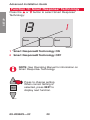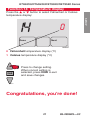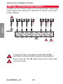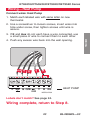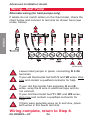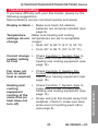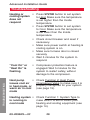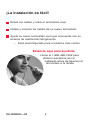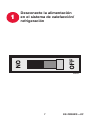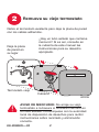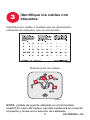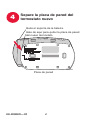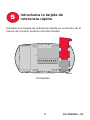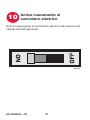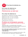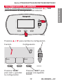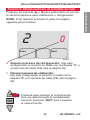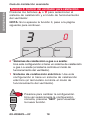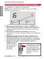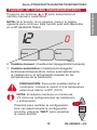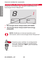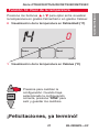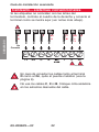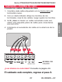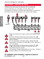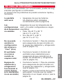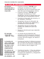
1
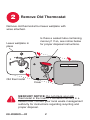
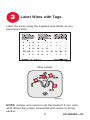
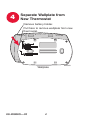
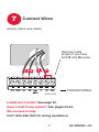
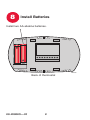
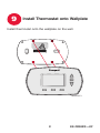
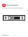
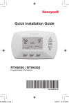
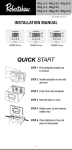
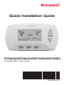
Quick Installation Guide
RTH6350/RTH6450/RET93E0/RET95E0
Programmable Thermostat
69-2696ES-03
Installation is Easy
Label wires and remove your old thermostat
Install and wire your new thermostat
Set your new thermostat to match your heating/cooling
system
– It is preset for the most common system
We are here to help.
Call 1-800-468-1502 for wiring
assistance before returning
the thermostat to the store.
69-2696ES—03ii
1
Turn Off Power to Heating/
Cooling System
M28097
169-2696ES—03
2
Remove Old Thermostat
Remove old thermostat but leave wallplate with
wires attached.
Leave wallplate in
place
Is there a sealed tube containing
mercury? If so, see notice below
for proper disposal instructions.
Old thermostat
Cover
M28099
MERCURY NOTICE: Do not place your old
thermostat in the trash if it contains mercury in a
sealed tube. Contact your local waste management
authority for instructions regarding recycling and
proper disposal.
69-2696ES—032
3
Label Wires with Tags
Label the wires using the supplied wire labels as you
disconnect them.
M28100
Wire Labels
M28093
NOTE: Jumper wire used on old thermostat? If yes, note
what letters the jumper connected and review in wiring
section.
369-2696ES—03
4
Separate Wallplate from
New Thermostat
Remove battery holder.
Pull here to remove wallplate from new
thermostat.
Wallplate
69-2696ES—034
M28343
5
Insert Quick Reference Card
Insert quick reference card into slot in back of thermostat.
M2834
M28344
Thermostat
569-2696ES—03
6
Mount Wallplate
Mount the new wallplate using the included screws
and anchors.
M28345
Drill 3/32-in. holes for plaster.
Drill 3/16-in. holes for drywall.
Use hammer to tap the anchors into the wall.
69-2696ES—036
7
Connect Wires
Simply match wire labels.
Remove metal
jumper if you have
both R and Rc wires.
G W
Y2 W2 G
W
Y
Y
R
R Rc
CONVENTIONAL
MCR31270A
Labels don’t match? See page 22.
Have a Heat Pump system? See pages 23-24.
We are here to help.
Call 1-800-468-1502 for wiring assistance.
769-2696ES—03
8
Install Batteries
Install two AA alkaline batteries.
M28346
Back of thermostat
69-2696ES—038
9
Install Thermostat onto Wallplate
Install thermostat onto the wallplate on the wall.
MCR31271
969-2696ES—03
10
Turn Power Back On
Turn the power back on to the heating/cooling system.
M28098
69-2696ES—0310
11
If your system type is...
If your system type is:
q Single Stage Heat and Cool
Congratulations, you’re done!
If your system type is:
q Multistage Heat and Cool
q Heat Pump* without Backup Heat
q Heat Pump* with Backup Heat
q Heat Only
q Cool Only
Continue with advanced installation
on page 12 to match your thermostat to your system
type.
*Heat Pump—an air conditioner that provides cooling in the
summer, and also runs in reverse in the winter to provide
heating.
If you are not sure of your system type or if you have
other questions, call us toll-free at 1-800-468-1502.
This thermostat works on 24 volt or 750 mV systems. It will
NOT work on 120/240 Volt systems.
1169-2696ES—03
Advanced Installation
System setup........................................................................13
Wiring...................................................................................22
Troubleshooting....................................................................25
Customer assistance............................................................27
Limited warranty...................................................................28
RTH6350/RTH6450/RET93E0/RET95E0 Series
About your
System
setup
new thermostat
Press and hold the s and FAN buttons until the screen
changes (approximately 5 seconds).
SETUP
WIRING
M28348
Function
Setting
1
0
Next
M28349
Press DONE to exit
and save settings.
Press NEXT to advance
to next function.
1369-2696ES—03
TROUBLESHOOTING
Done
ASSISTANCE
Press s or t to change settings.
Advanced Installation Guide
Function 1: System type
SETUP
Press the s or t button to select the type
of system you have in your home:
1
Done
0
Next
WIRING
M28350
0 Heating & cooling: Gas, oil or electric heating with
central air conditioning.
1 Heat pump: Outside compressor provides both heating
and cooling without backup or auxiliary heat.
ASSISTANCE
2 Heating only: Gas, oil or electric heating without
central air conditioning.
3 Heating only with fan: Gas, oil or electric heating
without central air conditioning. (Use this setting if you
could turn the fan on and off with a fan switch on your
old thermostat.)
4 Cool only: Central air conditioning only.
5 Heat Pump: Outside compressor provides both heating
and cooling with backup or auxiliary heating.
TROUBLESHOOTING
6 Heat/Cool Multiple Stages: Two heat stages (wires on W
and W2), two cooling stages (wires on Y and Y2).
7 Heat/Cool Multiple Stages: Two heat stages (wires on
W and W2), one cooling
stage (wire on Y).
Press to change
setting. When
8 Heat/Cool Multiple
correct setting is
Stages: One heat stage
selected, press
(wire on W), two cooling
NEXT to display
stages (wires on Y and
next function.
Y2).
M28351
69-2696ES—0314
RTH6350/RTH6450/RET93E0/RET95E0 Series
Function 2: Heat pump changeover valve
Press the s or t button to select whether your changeover valve is used in heating or cooling:
Done
0
WIRING
2
SETUP
NOTE: If Function 2 does not appear, please turn to the
next page to continue.
Next
1 Heating changeover valve: Use this setting if you
connected a wire labeled “B” to the O/B wire terminal
(see page 23).
M28351
1569-2696ES—03
TROUBLESHOOTING
Press to change setting.
When correct setting is
selected, press NEXT to
display next function.
ASSISTANCE
M28352
0 Cooling changeover valve: Use this setting if you
connected a wire labeled “O” to the O/B wire terminal
(see page 23).
Advanced Installation Guide
Function 3: Heating fan control
NOTE: If Function 3 does not appear, please turn to the
next page to continue.
3
WIRING
SETUP
Press the s or t button to select your heating system
and fan operation:
Done
0
Next
0 Gas or oil heat: Use this setting if you have a gas or
oil heating system (system controls fan operation).
1 Electric heat: Use this setting if you have an electric
heating system (thermostat controls fan operation).
TROUBLESHOOTING
ASSISTANCE
M28353
Press to change setting.
When correct setting is
selected, press NEXT to
display next function.
M28351
69-2696ES—0316
RTH6350/RTH6450/RET93E0/RET95E0 Series
Function 5: Heating cycle rate
Press the s or t button to select your heating system
and optimize its operation:
5
5
WIRING
Done
SETUP
NOTE: If Function 5 does not appear, please turn to the
next page to continue.
Next
M28354
9 Electric furnace: Use this setting if you have any type
of electric heating system.
ASSISTANCE
5 Gas or oil furnace: Use this setting if you have a
standard gas or oil furnace that is less than 90%
efficient.
3 Hot water or high-efficiency furnace: Use this
setting if you have a hot water system or a gas furnace
of greater than 90% efficiency.
Press to change setting.
When correct setting is
selected, press NEXT to
display next function.
M28351
1769-2696ES—03
TROUBLESHOOTING
1 Gas/oil steam or gravity system: Use this setting if
you have a steam or gravity heat system.
Advanced Installation Guide
About your
Function
6: new
Stage
thermostat
2 Heat cycle rate
NOTE: If Function 6 does not appear, please turn to the
next page to continue.
6
WIRING
SETUP
Press the s or t button to select your heating system
and optimize its operation:
Done
5
Next
ASSISTANCE
MCR31272
5 Gas or oil furnace: Use this setting if you have a
standard gas or oil furnace that is less than 90%
efficient.
9 Electric furnace: Use this setting if you have any type
of electric heating system.
TROUBLESHOOTING
3 Hot water or high-efficiency furnace: Use this
setting if you have a hot water system or a gas furnace
of greater than 90% efficiency.
1 Gas/oil steam or gravity system: Use this setting if
you have a steam or gravity heat system.
Press to change setting.
When correct setting is
selected, press NEXT to
display next function.
M28351
69-2696ES—0318
RTH6350/RTH6450/RET93E0/RET95E0 Series
Function 12: Manual/Auto Changeover
Press the s or t button to select Manual or Auto
Changeover:
Done
0
Next
WIRING
12
SETUP
NOTE: If Function 12 does not appear, please turn to the
next page to continue. This function is only available on the
RTH6450/RET95E0.
M28355
1 Automatic Changeover: (Heat/Off/Cool/Auto)
Automatically turns on heat or cool based on room
temperatures.
CAUTION: To avoid possible compressor damage,
set to option 0 if the outside temperature drops
below 50 ºF (10 ºC).
Press to change setting.
When correct setting is
selected, press NEXT to
display next function.
M28351
1969-2696ES—03
TROUBLESHOOTING
NOTE: System maintains a minimum 3 ºF difference
between heat and cool settings.
ASSISTANCE
0 Manual Changeover: (Heat/Off/Cool)
Advanced Installation Guide
Function 13: Smart Response Technology
®
Press the s or t button to select Smart Response
Technology:
SETUP
®
WIRING
13
Done
1
Next
M28356
1 Smart Response® Technology ON
TROUBLESHOOTING
ASSISTANCE
0 Smart Response® Technology OFF
NOTE: See Operating Manual for information on
Smart Response® Technology.
Press to change setting.
When correct setting is
selected, press NEXT to
display next function.
M28351
69-2696ES—0320
RTH6350/RTH6450/RET93E0/RET95E0 Series
Function 14: Temperature display
Press the s or t button to select Fahrenheit or Celsius
temperature display:
Next
M28357
WIRING
Done
0
SETUP
14
0Fahrenheit temperature display (°F)
1Celsius temperature display (°C)
Congratulations, you’re done!
2169-2696ES—03
TROUBLESHOOTING
M28351
ASSISTANCE
Press to change setting.
When correct setting is
selected, press DONE to exit
and save changes.
Advanced Installation Guide
SETUP
Wiring—Conventional System
If labels do not match letters on the thermostat, check the
chart below and connect to terminal as shown here (see
notes, below).
C
Y2 W2 G
W
F
Y
W1
H
R
Y1
M
RH
4
V
Rc
R
WIRING
X
B
W2
G
W
TROUBLESHOOTING
ASSISTANCE
Y2
Y
R
Rc
MCR31274B
If wires will be connected to both R and Rc
terminals, remove metal jumper (see page 6).
Do not use C, X or B. Wrap bare end of wire with
electrical tape.
69-2696ES—0322
RTH6350/RTH6450/RET93E0/RET95E0 Series
Wiring—Heat Pump
Connect wires: Heat Pump
2. Use a screwdriver to loosen screws, insert wires into
hole under screw, then tighten screws until wire is
secure.
SETUP
1. Match each labeled wire with same letter on new
thermostat.
3.If E and Aux do not each have a wire connected, use
a small piece of wire to connect them to each other.
Aux
E
G O/B
Y
R
Y
R Rc
HEAT PUMP
MCR31276A
Labels don’t match? See page 24.
Wiring complete, return to Step 8.
2369-2696ES—03
TROUBLESHOOTING
L
O
ASSISTANCE
Aux G
WIRING
4. Push any excess wire back into the wall opening.
Advanced Installation Guide
Wiring—Heat Pump
SETUP
Alternate wiring (for heat pumps only)
If labels do not match letters on the thermostat, check the
chart below and connect to terminal as shown here (see
notes, below).
4
5
C
TROUBLESHOOTING
ASSISTANCE
WIRING
X
B
E AUX G
L
F
X
X2
L
W
W1
W2
Aux
E
O
F
G
Y
H
B
O/B
R
Y1
M
Y
V
VR
R
Rc
R
Rc
2
MCR31275B
Leave metal jumper in place, connecting R & Rc
terminals.
If your old thermostat had both V and VR wires, stop
now and contact a qualified contractor for help.
5
If your old thermostat had separate O and B
wires, wrap the B wire in electrical tape and do
not connect.
If your old thermostat had Y1, W1 and W2 wires,
stop now and contact a qualified contractor for
help.
If there were seperate wires on E and Aux, place
both wires in the Aux/E terminal.
Wiring complete, return to Step 8.
69-2696ES—0324
RTH6350/RTH6450/RET93E0/RET95E0 Series
Troubleshooting
Fan does not
• Check Function 3: Heating Fan
Control to make sure it is set to
turn on when
match your heating equipment (see
heat is required
page 16).
• Check Function 1: System Type to
make sure it is set to match your
heating and cooling equipment (see
page 14).
• Grasp and pull thermostat away from
wallplate. Check to make sure bare
wires are not touching each other
(see page 6).
2569-2696ES—03
TROUBLESHOOTING
Heating and
cooling
equipment
running at the
same time (or
heat does not
turn off)
ASSISTANCE
Cannot change • Check Function 1: System Type to
make sure it is set to match your
system setting
heating and cooling equipment (see
to Cool
page 14).
WIRING
Display is blank • Make sure fresh AA alkaline
batteries are correctly installed (see
page 8).
Make sure heating and cooling
Temperature
settings do not temperatures are set to acceptable
ranges:
change
• Heat: 40° to 90 °F (4.5° to 32 °C).
• Cool: 50° to 99 °F (10° to 37 °C).
SETUP
If you have difficulty with your thermostat, please try the
following suggestions.
Most problems can be corrected quickly and easily.
Advanced Installation Guide
Heating or
• Press SYSTEM button to set system
cooling system
to Heat. Make sure the temperature
does not
is set higher than the Inside
respond
temperature.
• Press SYSTEM button to set system
to Cool. Make sure the temperature
is set lower than the Inside
temperature.
• Check circuit breaker and reset if
necessary.
• Make sure power switch at heating &
cooling system is on.
• Make sure furnace door is closed
securely.
• Wait 5 minutes for the system to
respond.
TROUBLESHOOTING
ASSISTANCE
WIRING
SETUP
Troubleshooting
“Cool On” or
“Heat On” is
flashing
• Compressor protection feature is
engaged. Wait 5 minutes for the
system to restart safely, without
damage to the compressor.
Heat pump
• Check Function 2: Heat Pump
Changeover Valve to make sure it is
issues cool air
properly configured for your system
in heat mode, or
(see page 15).
warm air in cool
mode
Heating system • Check Function 1: System Type to
make sure it is set to match your
is running in
heating and cooling equipment (see
cool mode
page 14).
69-2696ES—0326
RTH6350/RTH6450/RET93E0/RET95E0 Series
Customer assistance
SETUP
For assistance with this product, please visit
http://yourhome.honeywell.com
or call Honeywell Customer Care toll-free at
1-800-468-1502.
To save time, please remove the battery holder and note
your model number and date code before calling.
To order, please call Honeywell Customer Care toll-free at
1-800-468-1502.
WIRING
Accessories/replacement parts
Battery holder................................. Part No. 50007072-001
Cover plate assembly*.................... Part No. 50002883-001
ASSISTANCE
*Use to cover marks left by old thermostats.
TROUBLESHOOTING
2769-2696ES—03
Advanced Installation Guide
TROUBLESHOOTING
ASSISTANCE
WIRING
SETUP
1-year limited warranty
Honeywell warrants this product, excluding battery, to be free from
defects in the workmanship or materials, under normal use and
service, for a period of one (1) year from the date of purchase by
the consumer. If at any time during the warranty period the product is determined to be defective or malfunctions, Honeywell shall
repair or replace it (at Honeywell’s option).
If the product is defective,
(i) return it, with a bill of sale or other dated proof of purchase, to
the place from which you purchased it; or
(ii) call Honeywell Customer Care at 1-800-468-1502. Customer
Care will make the determination whether the product should be
returned to the following address: Honeywell Return Goods, Dock
4 MN10-3860, 1885 Douglas Dr. N., Golden Valley, MN 55422, or
whether a replacement product can be sent to you.
This warranty does not cover removal or reinstallation costs. This
warranty shall not apply if it is shown by Honeywell that the defect
or malfunction was caused by damage which occurred while the
product was in the possession of a consumer.
Honeywell’s sole responsibility shall be to repair or replace the
product within the terms stated above. HONEYWELL SHALL
NOT BE LIABLE FOR ANY LOSS OR DAMAGE OF ANY
KIND, INCLUDING ANY INCIDENTAL OR CONSEQUENTIAL
DAMAGES RESULTING, DIRECTLY OR INDIRECTLY, FROM
ANY BREACH OF ANY WARRANTY, EXPRESS OR IMPLIED,
OR ANY OTHER FAILURE OF THIS PRODUCT. Some states do
not allow the exclusion or limitation of incidental or consequential
damages, so this limitation may not apply to you.
THIS WARRANTY IS THE ONLY EXPRESS WARRANTY
HONEYWELL MAKES ON THIS PRODUCT. THE DURATION OF
ANY IMPLIED WARRANTIES, INCLUDING THE WARRANTIES
OF MERCHANTABILITY AND FITNESS FOR A PARTICULAR
PURPOSE, IS HEREBY LIMITED TO THE ONE-YEAR
DURATION OF THIS WARRANTY.
Some states do not allow limitations on how long an implied warranty lasts, so the above limitation may not apply to you. This
warranty gives you specific legal rights, and you may have other
rights which vary from state to state.
If you have any questions concerning this warranty, please
write Honeywell Customer Relations, 1985 Douglas Dr, Golden
Valley, MN 55422 or call 1-800-468-1502. In Canada, write Retail
Products ON15-02H, Honeywell Limited/ Honeywell Limitée, 35
Dynamic Drive, Toronto, Ontario M1V4Z9.
69-2696ES—0328
MERCURY NOTICE: Do not place your old
thermostat in the trash if it contains mercury in a
sealed tube. Contact your local waste management
authority for instructions regarding recycling and
proper disposal.
CAUTION: To avoid possible compressor damage,
do not run air conditioner if the outside temperature
drops below 50 °F (10 °C).
Automation and Control Solutions
Honeywell Limited-Honeywell Limitée
35 Dynamic Drive
Toronto, Ontario M1V 4Z9
http://yourhome.honeywell.com
® U.S. Registered Trademark
© 2012 Honeywell International Inc.
69-2696ES—03 M.S. Rev. 11-12
Printed in U.S.A.
Guía de instalación rápida
RTH6350/RTH6450/RET93E0/RET95E0
Termostato programable
69-2696ES-03
¡La instalación es fácil!
Rotule los cables y retire el termostato viejo
Instale y conecte los cables de su nuevo termostato
Ajuste su nuevo termostato para que concuerde con su
sistema de calefacción/refrigeración
– Está preconfigurado para el sistema más común
Estamos aquí para ayudarle.
Llame al 1-800-468-1502 para
obtener asistencia con el
cableado antes de devolver el
termostato a la tienda.
69-2696ES—03ii
1
Desconecte la alimentación
en el sistema de calefacción/
refrigeración
M28097
169-2696ES—03
2
Remueva su viejo termostato
Retire el termostato existente pero deje la placa de pared
con los cables adheridos.
Deje la placa
de pared en
su lugar
¿Hay un tubo sellado que contiene
mercurio? Si es así, consulte en
la cubierta de este manual las
instrucciones para su desecho
apropiado.
Termostato viejo
Cubierta
M28099
AVISO DE MERCURIO: No arroje su viejo
termostato a la basura si contiene mercurio en
un tubo sellado. Comuníquese con la autoridad
local de disposición de desechos para recibir
instrucciones sobre reciclado y eliminación
correcta.
69-2696ES—032
3
Identifique los cables con
etiquetas
Identifique los cables a medida que los desconecta,
utilizando las etiquetas que se suministran.
M28100
Rótulos para los cables
M28093
NOTA: ¿Cable de puente utilizado en el termostato
usado? En caso afirmativo, escriba cuáles letras conecta
el puente y revise en la sección de cableado.
369-2696ES—03
4
Separe la placa de pared del
termostato nuevo
Quite el soporte de la batería.
Hale de aquí para quitar la placa de pared
del nuevo termostato.
Placa de pared
69-2696ES—034
M28343
5
Introduzca la tarjeta de
referencia rápida
Introduzca la tarjeta de referencia rápida en el interior de la
ranura de la parte posterior del termostato.
M2834
M28344
Termostato
569-2696ES—03
6
Monte la placa de pared
Monte la nueva placa de pared utilizando los tornillos y
anclajes que se suministran.
M28345
Taladre agujeros de 3/32 in. (2,4 mm) en yeso.
Taladre agujeros de 3/16 in. (4,8 mm) en paneles de yeso.
Utilice un martillo para golpear ligeramente los anclajes en
la pared.
69-2696ES—036
7
Conecte los cables
Simplemente haga corresponder las etiquetas de los cables.
Retire el empalme
metálico si tiene
los cables “R” y
“Rc”.
G W
Y2 W2 G
W
Y
Y
R
R Rc
CONVENCIONAL
MCR31270A
¿Los rótulos no coinciden? Ver página 22.
¿Tiene un sistema de bomba de calor? Ver página 23-24.
Estamos aquí para ayudarle.
Llame al 1-800-468-1502 para asistencia con el
cableado.
769-2696ES—03
8
Instale las baterías
Instale dos baterías alcalinas AA en la parte de atrás del
termostato.
M28346
Parte de atrás del termostato
69-2696ES—038
9
Instale el termostato en la placa de
pared
Instale el termostato en la placa de pared sobre la pared.
MCR31271
969-2696ES—03
10
Active nuevamente el
suministro eléctrico
Active nuevamente el suministro eléctrico del sistema de
calefacción/refrigeración.
M28098
69-2696ES—0310
11
Si su tipo de sistema es...
Si su tipo de sistema es:
q Calor y frío de una sola etapa
¡Felicitaciones, ya está listo!
Si su tipo de sistema es:
q Calefacción y refrigeración de etapas múltiples
q Bomba de calor* sin calor de respaldo
q Bomba de calor* con calor de respaldo
q Calefacción únicamente
q Refrigeración únicamente
Continúe con la instalación avanzada
en la página 12 para adaptar el termostato a su tipo de
sistema.
*Bomba de calor—un acondicionador de aire que
proporciona enfriamiento en el verano y también funciona en
reversa en el invierno, proporcionando calor.
Si no está seguro del tipo de sistema que tiene o si tiene
otras preguntas, llámenos gratis al
1-800-468-1502.
Este termostato funciona con sistemas de 24 voltios o 750
mV. NO funciona con sistemas de 120/240 voltios.
1169-2696ES—03
Guía de instalación avanzada
Cómo cambiar la configuración............................................13
Cableado...............................................................................22
En caso de dificultades........................................................25
Asistencia al cliente..............................................................27
Garantía limitada..................................................................28
Serie RTH6350/RTH6450/RET93E0/RET95E0
About your new
Configuración
del
thermostat
sistema
CONFIGURACIÓN
Pulse y mantenga presionados los botones s y “FAN”
para introducir la configuración del sistema.
WIRING
M28348
Función
Configuración
1
Next
M28349
Presione “DONE”
para salir y guardar
la configuración.
Presione “NEXT” para
avanzar a la siguiente
función.
1369-2696ES—03
TROUBLESHOOTING
Done
0
ASSISTANCE
Presione s o t para cambiar la configuración.
Guía de instalación avanzada
CONFIGURACIÓN
Función 1: Tipo de sistema
Presione los botones s o t para seleccionar el tipo de
sistema de su hogar:
0 Calefacción y refrigeración:
Sistema de calefacción a gas,
a aceite o eléctrico con aire
acondicionado.
Done
Next
1 Bomba de calor: El
compresor externo proporciona
tanto calefacción como
refrigeración sin calefacción de respaldo o auxiliar.
2 Calefacción únicamente: Sistema de calefacción a gas, a
aceite o eléctrico sin aire acondicionado central.
3 Calefacción únicamente con ventilador: Sistema
de calefacción a gas, a aceite o eléctrico sin aire
acondicionado central (use esta configuración si puede
encender o apagar el ventilador con un interruptor de
ventilador o con el viejo termostato).
4 Refrigeración únicamente: Aire acondicionado central
únicamente.
Presione para
5 Bomba de calor: El
cambiar la
compresor externo
configuración. Una
proporciona tanto calefacción
vez seleccionada
como refrigeración con
la configuración
calefacción de respaldo o
correcta, presione
auxiliar.
“NEXT” para
6 Etapas múltiples de
visualizar la nueva
calefacción/refrigeración:
M28351
función.
Dos etapas de calefacción
(cables en W y W2), dos
etapas de refrigeración (cables en Y y Y2).
7 Etapas múltiples de calefacción/refrigeración: Dos
etapas de calefacción (cables en W y W2), una etapa de
refrigeración (cable en Y).
8 Etapas múltiples de calefacción/refrigeración: Una
etapa de calefacción (cable en W), dos etapas de
refrigeración (cables en Y y Y2).
69-2696ES—0314
1
0
TROUBLESHOOTING
ASSISTANCE
WIRING
M28350
Serie RTH6350/RTH6450/RET93E0/RET95E0
Función 2: Válvula inversora de la bomba de calor
NOTA: Si no aparece la función 2, pase a la página
siguiente para continuar.
Done
0
WIRING
2
CONFIGURACIÓN
Presione los botones s o t para seleccionar el uso de
la válvula inversora para calefacción o refrigeración:
Next
1 Válvula inversora de calefacción:
Use esta configuración si conectó un cable con la
etiqueta “B” a un terminal de cable O/B (vea la página
23).
M28351
1569-2696ES—03
TROUBLESHOOTING
Presione para cambiar la configuración.
Una vez seleccionada la configuración
correcta, presione “NEXT” para visualizar
la nueva función.
ASSISTANCE
M28352
0 Válvula inversora de refrigeración: Use esta
configuración si conectó un cable con la etiqueta “O” a
un terminal de cable O/B (vea la página 23).
Guía de instalación avanzada
NOTA: Si no aparece la función 3, pase a la página
siguiente para continuar.
3
WIRING
CONFIGURACIÓN
Función 3: Control del ventilador para calefacción
Presione los botones s o t para seleccionar el
sistema de calefacción y el modo de funcionamiento
del ventilador:
TROUBLESHOOTING
ASSISTANCE
Done
0
Next
M28353
0 Sistemas de calefacción a gas o a aceite:
Use esta configuración si tiene un sistema de calefacción
a gas o a aceite (el sistema controla el modo de
funcionamiento del ventilador).
1 Sistema de calefacción eléctrico: Use esta
configuración si tiene un sistema de calefacción
eléctrico (el termostato controla el modo de
funcionamiento del ventilador).
Presione para cambiar la configuración.
Una vez seleccionada la configuración
correcta, presione “NEXT” para visualizar
la nueva función.
M28351
69-2696ES—0316
Serie RTH6350/RTH6450/RET93E0/RET95E0
Función 5: Velocidad del ciclo térmico
5
WIRING
Done
5
CONFIGURACIÓN
Presione los botones s o t para seleccionar el sistema
de calefacción y optimizar la operación:
NOTA: Si no aparece la función 5, pase a la página
siguiente para continuar.
Next
M28354
M28351
1769-2696ES—03
TROUBLESHOOTING
Presione para cambiar la configuración.
Una vez seleccionada la configuración
correcta, presione “NEXT” para visualizar
la nueva función.
ASSISTANCE
5 Sistemas de calefacción a gas o a aceite: Use
esta configuración si tiene un sistema de calefacción
a gas o a aceite estándar de menos de un 90% de
efectividad.
9 Sistema de calefacción eléctrico: Use esta
configuración si tiene cualquier sistema de calefacción
eléctrico.
3 Sistema de calefacción de agua caliente o de
alta efectividad: Use esta configuración si tiene un
sistema de calefacción de agua caliente o un sistema
de calefacción a gas con más del 90% de efectividad.
1 Sistemas de vapor o de gravedad a gas o a
aceite: Use esta configuración si tiene un sistema de
calefacción de vapor o gravedad.
Guía de instalación avanzada
WIRING
CONFIGURACIÓN
Función 6: Índice del ciclo de calefacción en la etapa 2
Presione los botones s o t para seleccionar el sistema
de calefacción y optimizar la operación:
NOTA: Si no aparece la función 6, pase a la página
siguiente para continuar.
6
5
Done
Next
TROUBLESHOOTING
ASSISTANCE
MCR31272
5 Sistemas de calefacción a gas o a aceite: Use
esta configuración si tiene un sistema de calefacción
a gas o a aceite estándar de menos de un 90% de
efectividad.
9 Sistema de calefacción eléctrico: Use esta
configuración si tiene cualquier sistema de calefacción
eléctrico.
3 Sistema de calefacción de agua caliente o de
alta efectividad: Use esta configuración si tiene un
sistema de calefacción de agua caliente o un sistema
de calefacción a gas con más del 90% de efectividad.
1 Sistemas de vapor o de gravedad a gas o a
aceite: Use esta
configuración si
Presione para cambiar
tiene un sistema
la configuración. Una
de calefacción
vez seleccionada la
de vapor o
gravedad.
configuración correcta,
presione “NEXT” para
visualizar la nueva
función.
M28351
69-2696ES—0318
Serie RTH6350/RTH6450/RET93E0/RET95E0
Function 12: Cambio manual/automático
NOTA: Si la función 12 no aparece, pase a la página
siguiente para continuar. Esta función está sólo disponible
en el RTH6450/RET95E0.
12
WIRING
Done
0
CONFIGURACIÓN
Presione los botones s o t para seleccionar el
cambio manual o automático:
Next
M28355
1 Cambio automático: (Calefacción/Apagado/
Enfriamiento/Automático) Activa automáticamente
la calefacción o el enfriamiento basado en las
temperaturas de la habitación.
NOTA: El sistema mantiene un mínimo de
3ºF entre las configuraciones de calefacción
y enfriamiento.
Presione para cambiar la configuración.
Una vez seleccionada la configuración
correcta, presione “NEXT” para visualizar
la nueva función.
M28351
1969-2696ES—03
TROUBLESHOOTING
PRECAUCIÓN: Para evitar posibles daños al
compresor, coloque la opción 0 si la temperatura
externa es inferior a 50ºF (10ºC).
ASSISTANCE
0 Cambio manual: (Calefacción/Apagado/Enfriamiento)
Guía de instalación avanzada
®
Presione los botones s o t para seleccionar la
tecnología Smart Response :
®
13
WIRING
CONFIGURACIÓN
Function 13: Tecnología Smart Response
Done
1
Next
M28356
TROUBLESHOOTING
ASSISTANCE
1 Tecnología Smart Response® ACTIVADA
0 Tecnología Smart Response® Technology
APAGADA
NOTA: Refiérase al manual operativo para
información sobre la tecnología Smart Response®.
Presione para cambiar la configuración.
Una vez seleccionada la configuración
correcta, presione “NEXT” para visualizar
la nueva función.
M28351
69-2696ES—0320
Serie RTH6350/RTH6450/RET93E0/RET95E0
Función 14: Visor de la temperatura
0 Visualización de la temperatura en Fahrenheit (°F)
14
WIRING
Done
0
CONFIGURACIÓN
Presione los botones s o t para optar entre visualizar
la temperatura en grados Fahrenheit o en grados Celsius:
Next
M28357
M28351
¡Felicitaciones, ya terminó!
2169-2696ES—03
TROUBLESHOOTING
Presione para cambiar la
configuración. Cuando haya
seleccionado la configuración
correcta, presione “DONE” para
salir y guardar los cambios.
ASSISTANCE
1 Visualización de la temperatura en Celsius (°C)
Guía de instalación avanzada
SETUP
Cableado—sistemas convencionales
Si las etiquetas no coinciden con las letras del
termostato, controle el cuadro de la derecha y conecte el
terminal como se ilustra aquí (ver notas más abajo).
C
Y2 W2 G
CABLEADO
X
B
F
Y
W1
H
R
Y1
M
Rc
RH
4
V
R
No
Conecte
Y2
W2
G
W
Y
R
Rc
MSCR31274B
En caso de conectar los cables tanto al terminal
R como al Rc, quite el puente metálico (vea la
página 6).
No use los cables C, X ni B. Coloque cinta aisladora
en los extremos desnudos del cable.
TROUBLESHOOTING
ASSISTANCE
W
69-2696ES—0322
Serie RTH6350/RTH6450/RET93E0/RET95E0
Cableado—bomba de calor
Conecte los cables: Bomba de calor
2. Con un destornillador afloje los tornillos de los
terminales, inserte los cables, luego ajuste los tornillos.
4. Introduzca el excedente de cable en la abertura de la
pared.
Aux
E
G O/B
Y
R
Y
R Rc
MCR31276A
BOMBA DE
CALOR
¿Los rótulos no coinciden? Consulte la página 24.
El cableado está completo, regrese al paso 8.
2369-2696ES—03
TROUBLESHOOTING
L
O
ASSISTANCE
Aux G
CABLEADO
3.Si E y Aux no tienen un cable conectado cada uno,
utilice una pequeña pieza de cable para conectarlos
uno con otro.
SETUP
1. Coordine cada cable etiquetado con la misma letra del
termostato nuevo.
Guía de instalación avanzada
Cableado—bomba de calor
SETUP
Cableado alternativo (para bombas de calor únicamente)
Si las etiquetas no coinciden con las letras del
termostato, controle el cuadro de la derecha y conecte el
terminal como se ilustra aquí (ver notas más abajo).
4
TROUBLESHOOTING
E AUX G
L
C
X
B
F
X
X2
W
W1
W2
O
F
Y
H
B
R
Y1
M
Rc
V
VR
R
No
Conecte
ASSISTANCE
CABLEADO
5
L
Aux
E
G
O/B
Y
R
Rc
2
MSCR31275A
5
Deje el empalme en lugar, entre terminales de R
y Rc.
Si su termóstato existente tenía cables V y VR,
ahora pare y entre en contacto con un contratista
para la ayuda.
Si su termostato existente tenía cables O y B
separados, envuelva el cable B en cinta aislante y
no lo conecte.
Si su termostato existente tenía cables Y1, W1
y W2, ahora pare y entre en contacto con un
contratista para la ayuda.
Si hubiesen cables separados en E y Aux, coloque
ambos cables en el terminal Aux/E.
El cableado está completo, regrese al paso 8.
69-2696ES—0324
Serie RTH6350/RTH6450/RET93E0/RET95E0
En caso de dificultades
Asegúrese de que las temperaturas de
calor y frío estén configuradas en rangos
aceptables:
• Calor: De 40 °F a 90 °F
(de 4,5 °C a 32 °C).
• Frío: De 50 °F a 99 °F
(de 10 °C a 37 °C).
No se puede
cambiar la
configuración
del sistema a
“Cool” (Frío)
• Controle la función 1 (Tipo de sistema)
para asegurarse de que coincida con
el equipo de calefacción y refrigeración
(vea la página 14).
El ventilador
no arranca
cuando se
requiere calor
• Controle la función 3 (Control del
ventilador para calefacción) para
asegurarse de que coincida con el
equipo de calefacción y refrigeración
(vea la página 16).
Equipos de
• Controle la función 1 (Tipo de sistema)
para asegurarse de que coincida con
calefacción y
el equipo de calefacción y refrigeración
refrigeración
(vea la página 14).
funcionando al
mismo tiempo
• Sujete y quite el termostato de la placa
(o la calefacción
para pared. Controle que los cables
desnudos no se toquen entre sí (vea la
no se enciende)
página 6).
2569-2696ES—03
EN CASO DE DIFICULTADES
Las
configuraciones
de la temperatura
no cambian
ASSISTANCE
• Asegúrese de que las baterías
AA alcalinas estén instaladas
correctamente (vea la página 8).
WIRING
La pantalla
está vacía
SETUP
Si usted tiene dificultades con su termostato, pruebe las sugerencias que figuran a continuación.
La mayoría de los problemas se pueden solucionar rápida y
fácilmente.
Guía de instalación avanzada
El sistema
decalefacción o
enfriamiento no
responde
• Presione el botón “SYSTEM” para
configurar el sistema en “Heat”.
Asegúrese de que la temperatura sea
más alta que la temperatura interna.
• Presione el botón “SYSTEM” para
configurar el sistema en “Cool”.
Asegúrese de que la temperatura sea
más baja que la temperatura interna.
• Controle el interruptor de circuito y, si
es necesario, reinícielo.
• Asegúrese de que el interruptor de
energía del sistema de calefacción y
enfriamiento esté encendido.
• Asegúrese de que la puerta del
sistema de calefacción esté bien
cerrada.
• Espere 5 minutos para que responda
el sistema.
El mensaje
“Cool On” o
“Heat On” titila
• La función de la protección del
compresor está funcionando. Espere 5
minutos para que el sistema se vuelva
a iniciar de forma segura, sin dañar el
compresor.
La bomba de
calor emite aire
frío en el modo
de calor o aire
caliente en el
modo de frío
• Controle la función 2 (Válvula inversora
de la bomba de calor) para asegurarse
de que esté correctamente configurada
en su sistema (vea la página 15).
EN CASO DE DIFICULTADES
ASSISTANCE
WIRING
SETUP
En caso de dificultades
El sistema de
• Controle la función 1 (Tipo de sistema)
para asegurarse de que coincida con
calefacción está
el equipo de calefacción y refrigeración
funcionando en
(vea la página 14).
el modo de frío
69-2696ES—0326
Serie RTH6350/RTH6450/RET93E0/RET95E0
Ayuda al cliente
468-1502.
SETUP
Para obtener asistencia relacionada con este producto,
visite http://yourhome.honeywell.com o comuníquese con
el número gratuito de Atención al cliente de Honeywell 1 800
Para ahorrar tiempo, anote el número de modelo y el código
de fecha antes de llamar.
Accesorios y piezas de repuesto
Soporte de la batería........................ Part No. 50007072-001
Ensamblado de la placa
de cubierta*..................................... Part No. 50002883-001
ASISTENCIA
* Úselo para cubrir las marcas que dejan los
termostatos viejos.
WIRING
Para hacer el pedido, comuníquese con el número gratuito de
Atención al cliente de Honeywell 1-800-468-1502.
TROUBLESHOOTING
2769-2696ES—03
Guía de instalación avanzada
TROUBLESHOOTING
ASISTENCIA
WIRING
SETUP
Garantía limitada de 1 año
Honeywell garantiza este producto, a excepción de la
batería, por el término de un
(1) año contra cualquier defecto de fabricación o de los
materiales, a partir de la fecha de compra por parte del
consumidor. Si en cualquier momento durante el período
de garantía se verifica que el producto tiene un defecto o
que funciona mal, Honeywell lo reparará o reemplazará (a
elección de Honeywell).
Si el producto tiene defectos,
(i) devuélvalo, con la factura de venta u otra prueba de
compra fechada, al lugar donde lo compró; o
(ii) comuníquese con el Centro de atención al cliente de
Honeywell al 1-800-468-1502. Atención al cliente decidirá
si se debe devolver el producto a la siguiente dirección:
Devolución de mercaderías de Honeywell, Dock 4 MN103860, 1885 Douglas Dr.N., Golden Valley, MN 55422, o si se
le puede enviar un producto en reemplazo.
Esta garantía no cubre los costos de extracción o
reinstalación. Esta garantía no se aplicará si Honeywell
demuestra que el defecto o mal funcionamiento estaba
causado por daños ocurridos mientras el producto estaba en
posesión de un consumidor.
La única responsabilidad de Honeywell será reparar o
reemplazar el producto dentro de los plazos establecidos
anteriormente. HONEYWELL NO RESPONDERA POR
LA PÉRDIDA O DAÑO DE NINGUN TIPO, INCLUIDO EL
DAÑO INCIDENTAL O INDIRECTO DERIVADO, DIRECTA
O INDIRECTAMENTE, DEL INCUMPLIMIENTO DE LAS
GARANTIAS, EXPRESAS O IMPLICITAS, O DE OTRAS
FALLAS DE ESTE PRODUCTO. Algunos estados no permiten
la exclusión o limitación del daño incidental o indirecto,
entonces, esta limitación puede no resultar aplicable a su caso.
69-2696ES—0328
Serie RTH6350/RTH6450/RET93E0/RET95E0
Garantía limitada de 1 año
ASISTENCIA
Si tiene preguntas sobre la presente garantía, sírvase escribir
a Honeywell Customer Relations, 1985 Douglas Dr, Golden
Valley, MN 55422 o llamar al 1-800-468-1502.
En Canadá, escriba a Retail Products ON15-02H, Honeywell
Limited/Honeywell Limitée, 35 Dynamic Drive, Toronto,
Ontario M1V4Z9.
WIRING
Algunos estados no permiten las limitaciones sobre la
duración del período de una garantía implícita, entonces la
limitación anterior puede no resultar aplicable a su caso. Esta
garantía le brinda derechos legales específicos, y usted podrá
tener otros derechos que varían según el estado.
SETUP
LA PRESENTE GARANTIA ES LA UNICA GARANTIA
EXPRESA QUE HONEYWELL PROPORCIONA
RESPECTO DE ESTE PRODUCTO. LA DURACIÓN DE LAS
GARANTÍAS IMPLÍCITAS, INCLUÍDAS LAS GARANTÍAS
DE COMERCIABILIDAD Y APTITUD PARA UN OBJETIVO
PARTICULAR, ESTÁ LIMITADA A LA DURACIÓN DE UN
AÑO DE LA PRESENTE GARANTÍA.
TROUBLESHOOTING
2969-2696ES—03
AVISO DE MERCURIO: No arroje su viejo
termostato a la basura si contiene mercurio en
un tubo sellado. Comuníquese con la autoridad
local de disposición de desechos para recibir
instrucciones sobre reciclado y eliminación
correcta.
PRECAUCIÓN: Para evitar posibles daños al
compresor, no utilice el aire acondicionado si la
temperatura externa es inferior a 50 ºF (10 ºC).
Soluciones para automatización y control
Honeywell Limited-Honeywell Limitée
35 Dynamic Drive
Toronto, Ontario M1V 4Z9
http://yourhome.honeywell.com
® Marca registrada de los EE. UU.
© 2012 Honeywell International Inc.
69-2696ES—03 M.S. Rev. 11-12
Impreso en EE. UU.