1
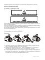
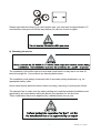
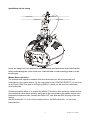
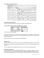
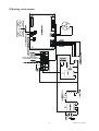
 PROFESSIONAL LIGHT USER’S MANUAL
MF-5
KEEP THIS MANUAL FOR FUTURE NEEDS
For your own safety, please read this user manual carefully before installing the device.
Every person involved with the installation, operation and maintenance of this device has
to:
-be qualified
-follow carefully the instructions of this manual
INTRODUCTION:
Thank you for having chosen this professional moving head.
You will see you have acquired a powerful and versatile device.
Unpack the device. Inside the box you should find: the fixture device, a power cable, an
XLR connection cable, a safety cable and this manual. Please check carefully that there is
no damage
2
WIT041 V1.1-01NR
Overview:
(1) Fixation screw
(2) DMX-In socket
(3) DMX-Out socket
(4) Power supply/Fuse holder
(5) Mounting bracket
(6) Ventilator
(7) DIP-switches
(8) Blackout controller jack
(9) MIC Sensitivity-button
(10) Lamp system
Features
·Lamp: Philips MSD 250/2 8500K, base : GY 9.5
·Control signal: standard DMX-512, 5 channels
·Stand alone operation with master/slave function, can be sound activated
·special color wheel with multi color pieces can make rainbow effect in both direction
·One gobo wheel with 5 rotating gobos, with gobo shaking, and black out
·Prism and prism rotation
3
WIT041 V1.1-01NR
·Preset program: 8 built in programs can be called up via DMX controller
SAFETY INSTRUCTIONS
This device has left the factory in perfect condition. In order to maintain this condition and to
ensure a safe operation, it is absolutely necessary for the user to follow the safety
instructions and warning notes written in this user manual.
If the device has been exposed to temperature changes due to environmental changes, do
not switch it on immediately. The arising condensation could damage the device. Leave the
device switched off until it has reached room temperature.
This device falls under protection-class I. Therefore it is essential that the device should be
earthed.
The electric connection must carry out by qualified person.
Make sure that the available voltage is not higher than stated at the end of this manual.
Make sure the power cord is never crimped or damaged by sharp edges. If this would be
the case, replacement of the cable must be done by an authorized dealer.
Always disconnect from the mains, when the device is not in use or before cleaning it. Only
handle the power cord by the plug. Never pull out the plug by tugging the power cord.
During initial start-up some smoke or smell may arise. This is a normal process and does
not necessarily mean that the device is defective, it should decrease gradually.
4
WIT041 V1.1-01NR
Please be aware that damages caused by manual modifications to the device are not
subject to warranty. Keep away from children and non-professionals.
GENERAL GUIDELINES
This device is a lighting effect for professional use on stages, in discotheques, theatres, etc.
This fixture is only allowed to be operated with the max alternating current which stated in
the technical specifications in the last page of this manual, the device was designed for
indoor use only.
Lighting effects are not designed for permanent operation. Consistent operation breaks
may ensure that the device will serve you for a long time without defects. Do not shake the
device.
Avoid brute force when installing or operating the device.
While choosing the installation-spot, please make sure that the device is not exposed to
extreme heat, moisture or dust. The minimum distance between light-output from the
projector and the illuminated surface must be more than 0,5 meter.
Always fix the fixture with an appropriate safety cable if you use the quick lock cam in
hanging up the fixture, please make sure the 4 quick lock fasteners turned in the quick lock
holes correctly.
Operate the device only after having familiarized with its functions. Do not permit operation
by persons not qualified for operating the device. Most damages are the result of
unprofessional operation.
Please use the original packaging if the device is to be transported.
For safety reasons, please be aware that all modifications on the device are forbidden.
If this device will be operated in any way different to the one described in this manual, the
product may suffer damages and the guarantee becomes void. Furthermore, any other
5
WIT041 V1.1-01NR
operation may lead to short-circuit, burns, electric shock, lamp explosion, crash, etc.
INSTALLATION INSTRUCTIONS
a) Installing or replacing the lamp
Before replacing the lamp let the lamp cool down, because during operation, the lamp can
reach very high temperature.
During the installation of halogen lamps do not touch the glass bulbs bare handed. Always
use a cloth to handle the lamps during insertion and removal.
Do not install lamps with a higher wattage. They generate higher temperatures than which
the device was designed for.
For the installation, you need one: MSD 250/2
Procedures:
1) Unscrew the 2 screws (A,B)on the bottom of the housing, holding the plate where the
lamp is underneath. Carefully remove the metal plate.
2) Carefully insert the lamp into the socket. Please remember there is only one way to
insert the lamp. Gently slide the lamp and its lamp holder back into place.
3) On the access plate there are 3 screws marked 1,2 and 3.which are used to adjust the
lamp holder in the lamp housing. You can adjust the 3 screws to fine-turn the position of
the lamp to get the maximum light output as shown below.
6
WIT041 V1.1-01NR
Please remember the lamp is not a hot-restrike type, you must wait for approximately 10
minutes after having turned off the lamp before you can turn it back on again.
b) Mounting the device
The installation of the effect has to be built and constructed in a way that it can hold 10
times the weight for 1 hour without any harming deformation.
The installation must always be secured with a secondary safety attachment, e.g. an
appropriate safety cable.
Never stand directly below the device when mounting, removing or servicing the fixture.
The operator has to make sure the safety relating and machine technical installations are
approved by an expert before taking the device into operation for the first time.
These installations have to be approved by a skilled person once a year.
7
WIT041 V1.1-01NR
Cautions:
The effect should be installed outside areas where persons may reach it, walk by or be
seated.
Overhead mounting requires extensive experience, including amongst others calculating
working load limits, installation material being used, and periodic safety inspection of all
installation material and the device. If you lack these qualifications, do not attempt the
installation yourself. Improper installation can result in bodily injury.
Before mounting make sure that the installation area can hold a minimum point load of 10
times the device’s weight.
Connect the fixture to the mains with the power plug.
8
WIT041 V1.1-01NR
installation via the clamp
Screw one clamp each via a M10 screw and nut directly into the bracket of the unit. Pull the
safety-chain through the eyelet on the rear of the unit and over the trussing system or a safe
fixation spot.
Master/Slave-operation
The master/slave-operation enables that several devices can be synchronized and
controlled by one master-device. On the rear panel of the LIGNTING EFFECT you can find
an XLR-jack (DMX Out) and an XLR-plug (DMX In), which can be used for connecting
several devices.
Choose the device which is to control the effects. This device then works as master-device
and controls all other slave-devices, which are to be connected to the master-device via a
balanced microphone lead. Connect the DMX OUT-jack with the DMX IN-plug of the next
device.
Set DIP-switch No. 11 to On for the master-device. Set DIP-switch No. 1 to on for all
slave-devices.
9
WIT041 V1.1-01NR
Occupation of the DIP-switches:
Blackout-socket
If you wish to lock the light output - e.g. via an optional footswitch (Blackout-mode), connect
your footswitch via a mono-jack plug to the Blackout-socket.
Occupation mono 1/4“ jack-plug:
DMX-512 connection / connection between fixtures
Only use a stereo shielded cable and 3-pin XLR-plugs and connectors in order to connect
the controller with the fixture or one fixture with another.
Occupation of the XLR-connection:
10
WIT041 V1.1-01NR
If you are using controllers with this occupation, you can connect the DMX-output of the
controller directly with the DMX-input of the first fixture in the DMX-chain. If you wish to
connect DMX-controllers with other XLR-outputs, you need to use adapter-cables.
Building a serial DMX-chain:
Connect the DMX-output of the first fixture in the DMX-chain with the DMX-input of the next
fixture. Always connect one output with the input of the next fixture until all fixtures are
connected.
DMX-512 connection with DMX terminator
For installations where the DMX cable has to run a long distance or is in an electrically
noisy environment, such as in a discotheque, it is recommended to use a DMX terminator.
This helps in preventing corruption of the digital control signal by electrical noise. For
normal products which do not have dip switches setting, the DMX terminator is simply an
XLR plug with a 120 Ω resistor connected between pins 2 and 3,which is then plugged into
the output XLR socket of the last fixture in the chain.
While on the MF-5 which with the dip Switches setting, if the DP12 is put to ON position
( downwards) the fixture gains the function of connecting with a 120 Ω resistor, then this
unit functions as the terminator of the DMX link.
Addressing
Each projector occupies 5 channels. To ensure that the control signals are properly
directed to each projector, the projector requires addressing. This is to be done for every
single projector by changing the DIP switches as set out in this table.
The starting address is defined as the first channel from which the LIGHTING EFFECT will
respond to the controller.
Please make sure that you don’t have any overlapping channels in order to control each
LIGHTING EFFECT correctly and independently from any other fixture on the DMX data
link. If two, three or more LIGHTING EFFECT are addressed similarly, they will work
similarly.
11
WIT041 V1.1-01NR
Occupation of the DIP-switches:
Connection with the mains
Connect the device to the mains with the enclosed power supply cable.
The occupation of the connection-cables is as follows:
The earth has to be connected!
If the device will be directly connected with the local power supply network, a disconnection
switch with a minimum opening of 3 mm at every pole has to be included in the permanent
electrical installation.
Lighting effects must not be connected to dimming-packs.
OPERATION
After you connected the effect to the mains, the LIGHTING EFFECT starts running. During
the Reset, the motors are trimmed and the device is ready for use within approximately 20
seconds.
Turn the objective-lens for adjusting the focus in order to obtain a sharp projection.
Stand Alone operation
In the Stand Alone mode, the LIGHTING EFFECT can be used without controller. You can
do without a controller as the LIGHTING EFFECT features a built-in microphone, which
provides automatic sound control. Disconnect the LIGHTING EFFECT from the controller
12
WIT041 V1.1-01NR
and set the DIP-switch 10 to On.
The lamp is automatically ignited as soon as the condenser microphone receives music
signals.
Call up the Auto program
In order to call up the Auto program, set all DIP-switches to Off.
Master/Slave-operation
Connect the master and slave-devices as desired above and set the DIP-switches
accordingly.
Please note: If you wish to change from one operating mode into another, you either have
to switch off the lamp/activate Blackout-mode or unplug the projector from the mains and
plug it again.
Auto Program MIC SENSITIVITY-button
1. Put the Dip-switch in the sound mode and adjust the sensitivity of the activated sound
by turning the MIC SENSITIVITY-button.
2. In the Auto Program mode (all Dip-switches to OFF) you can select different internal
programs with this button.
DMX-controlled operation
You can control the projectors individually via your DMX-controller. Every DMX-channel
has a different occupation with different features.
DMX channel´s functions and their values (5 DMX channels):
Channel 1
0-127
- Color:
Color indexing
128-187
Forwards rainbow effect from fast to slow
188-193
No rotation
194-255
Backwards rainbow effect from slow to fast
Channel 2 -
Rotating gobos, cont. rotation :
0-3
Close
4-7
Close & Motor reset
8-19
Close
20-39
Rot. gobo 1
40-59
Rot. gobo 2
60-79
Rot. gobo 3
80-99
Rot. gobo 4
100-120
Rot. gobo 5
121-147
Rot. gobo 1
shake
148-174
Rot. gobo 2
shake
13
WIT041 V1.1-01NR
175-201
Rot. gobo 3
shake
202-228
Rot. gobo 4
shake
229-255
Rot. gobo 5
shake
Channel 3 0-7
8-255
Channel 4 0-7
8-127
Gobo rotation :
No rotation
Rotation
Prism rotation :
No rotation
forwards prism rotation from fast to slow
128-135
No rotation
136-255
Backwards prism rotation from slow to fast
Channel 5 -
Auto Program:
0-23
Nomal
24-47
Auto Program 1
48-71
Auto Program 2
72-95
Auto Program 3
96-119
Auto Program 4
120-143
Auto Program 5
144-167
Auto Program 6
168-191
Auto Program 7
192-215
Auto Program 8
216-239
Auto Program 9
240-255
Auto Program 10
CLEANING AND MAINTENANCE
The operator has to make sure that safety-relating and machine-technical installations are
inspected by an expert after every four years in the course of an acceptance test. The
operator has to make sure that safety-relating and machine-technical installations are
inspected by a skilled person once a year.
The following points have to be considered during the inspection:
1) All screws used for installing the devices or parts of the device have to be tightly
connected and must not be corroded.
2) There must not be any deformations on housings, fixations and installation spots
(ceiling, suspension, trussing).
3) Mechanically moved parts like axles, eyes and others must not show any traces of
wearing (e.g. material abrading or damages) and must not rotate with unbalances.
4) The electric power supply cables must not show any damages, material fatigue (e.g.
porous cables) or sediments. Further instructions depending on the installation spot and
usage have to be adhered by a skilled installer and any safety problems have to be
removed.
14
WIT041 V1.1-01NR
We recommend a frequent cleaning of the device. Please use a moist, lint-free cloth. Never
use alcohol or solvents!
The objective lens will require weekly cleaning as smoke-fluid tends to building up residues,
reducing the light-output very quickly. The cooling-fans should be cleaned monthly.
The gobos may be cleaned with a soft brush. The interior of the fixture should be cleaned at
least annually using a vacuum-cleaner or an air-jet.
The dichroic color-filters, the gobo-wheel and the internal lenses should be cleaned
monthly.
To ensure a proper function of the gobo-wheel, we recommend lubrication in six month
intervals. The quantity of oil must not be excessive in order to avoid that oil runs out when
the gobo-wheel rotates.
There are no serviceable parts inside the device. Maintenance and service operations are
only to be carried out by authorized dealers.
Please refer to the instructions under "Installing/Replacing the lamp".
Replacing the fuse
If the fine-wire fuse of the device fuses, only replace the fuse by a fuse of same type and
rating.
Before replacing the fuse, unplug mains lead.
Procedure:
Step 1: Open the fuse holder on the rear-panel with a fitting screwdriver.
Step 2: Remove the old fuse from the fuse-holder.
Step 3: Install the new fuse in the fuse-holder.
Step 4: Replace the fuse-holder in the housing.
Should you need any spare parts, please use genuine parts.
If the power supply cable of this device becomes damaged, it has to be replaced by a
special power supply cable available at your dealer.
Should you have further questions, please contact your dealer.
15
WIT041 V1.1-01NR
TECHNICAL SPECIFICATIONS
Power supply :
□100VAC,50Hz;□110VAC,50Hz;□120VAC, 50Hz;□220VAC,50Hz;□230VAC,50Hz;□240VAC, 50Hz;
□98VAC,50Hz;□110VAC,60Hz;□120VAC,60Hz; □220VAC,60Hz;□230VAC,60Hz;□240VAC,60Hz;
Power consumption : max. 400 W
Lamp :
PHILIPS MSD250/2 GY9.5
Motors : 3 micro motors
Packing dimensions : 51 x 37 x 34 cm
Sound-control: via built-in microphone
Net weight : 10KGS;
Gross weight: 12KGS;
Remark : errors and omissions for every information given in this manual excepted. All
information is subject to change without prior notice.
16
WIT041 V1.1-01NR
PCB wiring circuit diagram
17
WIT041 V1.1-01NR