1
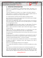
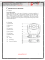
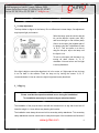
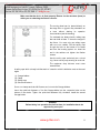
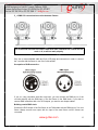
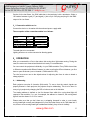
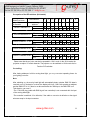
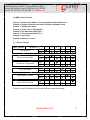
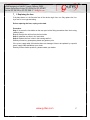
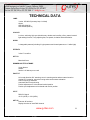
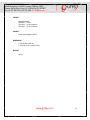
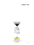
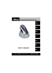
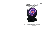
User Manual
MOVING HEAD
MODEL: 250S
www.g-lites.com
1
CONTENTS
1. - INTRODUCTION
4
2. - SAFETY INSTRUCTIONS
4
3. - OPERATING DETERMINATION
6
4. - DESCRIPTION OF THE DEVICE
7
4.1. – FEATURES
4.2. – OVERVIEW
7
7
5. – INSTALLATION
8
5.1. - INSTALLING/REPLACING THE LAMP
5.2. - LAMP ADJUSTMENT
5.3. – RIGGING
5.4. - DMX-512CONNECTION/CONNECTIONBETWEENFIXTURES
5.5. - CONNECTIONWITH THE MAINS
8
9
9
12
13
6. – OPERATION
14
6.1. – ADDRESSING
6.2. - DMX-PROTOCOL
6.3. - SPECIAL SETTINGS
14
16
16
7. - CLEANING AND MAINTENANCE
17
7.1. -REPLACING THE FUSE
18
TECHNICAL SPECIFICATION
19
GENERAL TROUBLESHOOTING
21
www.g-lites.com
2
IMPORTANT TERMS:
This manual covers important information about installation and operation of this
moving head. Please read this manual carefully before installing and operating
this Moving Head. Follow the safety precautions listed below:
A. Read this manual carefully and keep manual near moving head.
B. Follow the safety regulations mentioned in this manual when operating or
installing this fixture.
C. Warranty is void if the product is misused, damaged or modified in any
way, or for unauthorized repairs or parts
D. For maintenance or lamp replacement, disconnect the fixture from main
power before opening the moving head.
www.g-lites.com
3
250S
1.INTRODUCTION
Thank you for having chosen this MOVING HEAD LIGHT .You will see you have acquired a
powerful and versatile device.
Unpack your moving-head light.
Before you initial start-up, please make sure that there is no damage caused by
transportation.
Should there be any, consult your dealer and do not use the device.
2.SAFETY INSTRUCTIONS
CAUTION
Be careful with your operations. With a dangerous voltage
you can suffer a dangerous electric shock!
This device has left our premises in absolutely perfect condition. In order to maintain this
condition and to ensure a safe operation; it is absolutely necessary for the user to follow the
safety instructions and warning notes written in this user manual.
Important:
Damages caused by the disregard of this user manual are not subject to warranty. The
dealer will not accept liability for any resulting defects or problems.
If the device has been exposed to drastic temperature fluctuation (e.g. after transportation),
do not switch it on immediately. The arising condensation water might damage your device.
Leave the device switched off until it has reached room temperature.
This device falls under protection-class 1. The power plug must only be plugged into a
protection class 1 outlet.
Never let the power-cord contact with other cables! Handle the power-cord and all
connections with the mains with particular caution!
www.g-lites.com
4
Make sure that the available voltage is not higher than stated on the rear panel.
Make sure that the power-cord is never crimped or damaged by sharp edges. Check the
device and the power-cord from time to time.
Always disconnect from the mains, when the device is not in use or before cleaning it. Only
handle the power-cord by the plug. Never pull out the plug by tugging the power-cord.
During the initial start-up some or smell may arise. This is a normal process and does not
necessarily mean that the device has defects.
Caution: During the operation, the housing becomes very hot.
Danger of fire! Never install the device on highly flammable surfaces (e.g. fair carpet)!
HEALTH HAZARD!
Never look directly into the light source. As sensitive persons may suffer an
epileptic shock (especially meant for epileptics)!
www.g-lites.com
5
3.OPERATING DETERMINATIONS
This device is a moving-head spot for creating decorative effects. This product is only
allowed to be operated with an alternating current of 230V, 50Hz and was designed for
indoor use only.
This device is designed for professional use, e.g. on stages, in discotheques, theatres etc.
Lighting effects are not designed for permanent operation. Consistent operation breaks will
ensure that the device will serve you for a long time without defects.
Do not shake the device. Avoid brute force when installing or operating the device.
Never list the fixture by holding it at the projector-head, as the mechanics may be damaged.
Always hold the fixture at the transport handles.
When choosing the installation-spot, please make sure that the device is not exposed to
extreme heat, moisture or dust. There should not be any cables lying around. You endanger
your own and the safety of others!
The symbol
determines the minimum distance from lighted objects. The minimum
distance between light-output and the illuminated surface must be more than this value.
Make sure that the area below the installation place is blocked when rigging, un-rigging or
servicing the fixture.
Always fix the fixture with an appropriate safety-rope. Fix the safety-rope at the correct
fixation points only. The safety-rope must never be fixed at the transport handles!
Only operate the fixture after having checked that the housing is firmly closed and all screws
are tightly fastened.
The lamp must never be ignited if the objective-lens or any housing-cover is open, as
discharge lamps may explode and emit a high ultraviolet radiation, which may cause burns.
The maximum ambient temperature at=45℃ must never be exceeded.
Operate the device only after having familiarized with its functions. Do not permit operation
by persons not qualified for operating the device. Most damages are the result of
unprofessional operation!
Please use the original packaging if the device is to be transported.
Please consider that unauthorized modifications on the device are forbidden due to safety
reasons!
Never remove the serial barcode from the device as this would make the guarantee void.
If this device will be operated in any way different to the one described in this manual, the
product may suffer damages and the guarantee becomes void. Furthermore, any other
operation may lead to dangers like short-circuit, burns, electric shock, lamp explosion, crash
www.g-lites.com
6
etc.
4.DESCRIPTION OF THE DEVICE
4.1 Features
Powerful Moving-Head
Versatile Moving-Head with a wide range of illumination and decoration possibilities. 9
brilliant, dichroic colors plus white. 7 static metal gobos plus open. Auto focus. Strobe-effect
with 1-7 flashes per second. Exact positioning within 4500 Pan and 2700 Tilt. 8 DMXchannels –16 bit Pan/Tilt movement resolution. 8 DMX-channels –8 bit Pan/Tilt movement
resolution. 3-digit LED display for starting address. For bright 250W discharge lamp. Suitable
controllers: DMX Operator.
4.2 Overview
(1) Projector head
(2) Objective lens
(3) Yoke
(4) Power switch
(5) DMX-IN socket
(6) Carrying handle
(7) Power supply
(8) DMX-OUT socket
(9) Fuse
(10)
Display
(11)
DIP-switches
(12)
Function-DIP-switches
www.g-lites.com
7
5、INSTALLATION
5.1 Installing/replacing the lamp
DANGER TO LIFE!
Only install the lamp with the device switched off!
Unplug from mains before!
For the installation, you need one HSD250/MSD250 lamp.
Protection gloves, helmet with sight, leather apron
CAUTION!
The lamp has to be replaced when it is damaged or deformed due to the heat!
The lamp life given by the manufacturer must never be exceeded. This is why you need to
take notes on the operational time of the lamp and replace the lamp in time.
Keep exchanged lamp in a protective
container and remove accordingly.
During the operation, the lamp reaches
temperatures of up to 600℃.
Before replacing the lamp, unplug
mains lead and let the lamp cool down
(approx.10 minutes).
During the installation do not touch the
glass-bulbs bare-handed! Please follow
the lamp manufacturer’s notes!
Do not install lamps with a higher
wattage! Lamps with a higher wattage
generate temperatures the device was
not designed for. Damages caused by
non-observance are not subject to
warranty
Procedure:
Step 1: Unscrew the fixation screws of the lamp cover and remove it.
Step 2: Unscrew the knurled-head screws of the lamp holder and remove it.
Step 3: If replacing the lamp, remove the old lamp from the lamp holder.
Step 4: Insert the lamp into the lamp holder.
Step 5: Replace the lamp holder and tighten the knurled-head screws.
Step 6: Adjust the lamp as described under lamp adjustment.
Step 7: Replace the lamp cover and tighten the fixation screws.
www.g-lites.com
8
Do not operate this device with opened cover!
5.2 Lamp adjustment
The lamp holder is aligned at the factory. Due to differences between lamps, fine adjustment
may improve light performance.
Strike the lamp, open the shutter and the
iris, set the dimmer intensity onto 100%
and focus the light on flat surface (wall).
Center the hot-spot (the brightest part of
the beam) using the 3 adjustment screws
“A, B, C”. Turn one screw at a time to
drag the hot-spot, adjust the lamp until
the light is even.
To reduce a hot-spot, pull the lamp in by
turning all three screws “A, B, C”
clockwise 1/4-turn at a time until the light
is evenly distributed.
If the light is brighter around the edge than it is in the center, or if light output is low, the lamp
is too far back in the reflector. Push the lamp out by turning the screws “A, B, C”
counterclockwise 1/4-turn at a time the light is bright and evenly distributed.
5.3 Rigging
DANGER
Please consider the respective national norms during the installation!
The installation must only be carried out by an authorized dealer!
The installation of the projector has to be built and constructed in a way that it can hold 10
times the weight for 1 hour without any harming deformation.
The installation must always be secured with a secondary safety attachment. This secondary
safety attachment must be constructed in a way that no part of the installation can fall down if
www.g-lites.com
9
the main attachment fails.
When rigging, un-rigging or servicing the fixture staying in the area below the installation
place, on bridges, under high working places and other endangered areas is forbidden.
The operator has to make sure that safety-relating and machine-technical installations are
approved by an expert before taking into operation for the first time and after changes before
taking into operation another time.
The operator has to make sure that safety-relating and machine-technical installations are
approved by an expert after four year in the course of an acceptance test.
The operator has to make sure that safety-relating and machine-technical installations are
approved by a skilled person once a year.
Procedure:
The projector should be installed outside areas where persons may walk by or be seated.
IMPORTANT! OVERHEAD RIGGING REQUIRES EXTENSIVE EXPERIENCE, including
(but not limited to) calculating working load limits, installation material being used, and
periodic safety inspection of all installation material and the projector. If you lack these
qualifications, do not attempt the installation yourself, but instead use a professional
structural rigger. Improper installation can result in bodily injury and or damage to property.
The projector has to be installed out if the reach of people.
If the projector shall be lowered from the ceiling or high joists, professional trussing systems
have to be used. The projector must never be fixed swinging freely in the room.
Caution:
Projectors may cause severe injuries when crashing down! If you have doubts concerning
the safety of a possible installation, do NOT install the projector!
Before rigging make sure that the installation area can hold a minimum point load of 10 times
the projector’s weight.
DANGER OF FIRE!
When installing the device, make sure there is no highly-inflammable material
(decoration articles, etc.) within a distance of min.0.5m.
CAUTION!
Use 2 appropriate clamps to rig the fixture on the truss.
Follow the instructions mentioned at the bottom of the base.
www.g-lites.com
10
Make sure that the device is fixed properly! Ensure that the structure (truss) to
which you are attaching the fixture is secure.
The moving head can be placed directly on
the stage floor or rigged in any orientation on
a truss without altering its operation
characteristics (see the drawing).
For overhead use, always install a safety rope
that can hold at least 12 times the weight of
the fixture. You must only use safety ropes
with screw on carbine. Pull the safety rope
through the hole on the bottom of the base
and over the trussing system etc. insert the
end in the carbine and tighten the fixation
screws.
Use the safety rope exclusively as a closed
ring. Never use by only securing at each end.
The maximum drop distance must never
exceed 20cm.
A safety rope which already hold the strain of a crash or which is defective must not be used
again.
(1)
(2)
(3)
(4)
Omega-holders
Clamp
Safety-rope
Quick-lock fastener
Screw one clamp each via a M12 screw and nut onto the Omega-holders.
Insert the quick-lock fasteners of the first Omega-holder into the respective holes on the
bottom of the device. Tighten the quick-lock fasteners fully clockwise. Install the second
Omega-holder.
DANGER
Before taking into operation for the first time, the installation has to be
approved by an expert!
www.g-lites.com
11
5.4 DMX-512 connection/connection between fixtures
The wires must not come into contact with each other; otherwise the fixtures will not
work at all, or will not work properly.
Only use a stereo shielded cable and 3-pin XLR-plugs and connectors in order to connect
the controller with the fixture or one fixture with another.
Occupation of XLR-connection:
If you are using controllers with this occupation, you can connect the DMX-output of the
controller directly with the DMX-input of the first fixture in the DMX-chain. If you wish to
connect DMX-controllers with other XLR-outputs, you need to use adapter-cables.
Building a serial DMX-chain:
Connect the DMX-output of the first fixture in the DMX-chain with the DMX-input of the next
fixture. Always connect one output with the input of the next fixture until all fixtures are
connected.
www.g-lites.com
12
Caution: At the last fixture, the DMX-cable has to be terminated with a terminator. Solder a
120 resistor between signal (“C”) and signal (+) into a 3-pin XLR-plug and plug it in the DMXoutput of the last fixture.
5.5 Connection with the mains
Connect the device to the mains with the enclosed power supply cable.
The occupation of the connection-cables is as follows:
Cable
Pin
International
Brown
Live
L
Blue
Neutral N
Yellow/Green
Earth
The earth has to be connected!
Lighting effects must not be connected to dimming-packs.
6.OPERATION
After you connected the effect to the mains, this moving-head light starts running. During the
reset, the motors are trimmed and the device is ready for use afterwards.
You can control the projectors individually via your DMX-controller. Every DMX-channel has
a different occupation with different features. In order to call up the different features, you first
have to open the shutter (control channel 4, DMX-value 241-255).
Turn the focus-screw next to the objective-lens for adjusting the focus in order to obtain a
sharp projection.
6.1 Addressing
Each projector occupies 8 channels (8-bit-mode). To ensure that the control signals are
properly directed to each projector, the projector requires addressing. This is to be done for
every single projector by changing the DIP switches as set out in this table.
The starting address is defined as the first channel from which this moving-head light will
respond to the controller. If you set, for example, the address to channel 6, the moving-head
light will use the channel 6 to 13 for control.
Please make sure that you don’t have any overlapping channels in order to control each
moving-head light correctly and independently from and other fixture on the DMX data link. If
two, three or more moving-head light is addressed similarly, they will work similarly.
www.g-lites.com
13
Occupation of the DIP-switches (8-bit-mode):
Setting the DMX
Starting address:
Projector number
& channels
DIP-switch no.
DMX-starting
address:
ON
Device 1-channels 1-8
OFF
Device 2-channels 9-16
ON
OFF
Device 3-channels 17-24
ON
OFF
Device 4-channels 25-32
ON
OFF
Device 5-channels 33-40
ON
OFF
1
1
2
2
3
4
4
8
5
6
7
8
9
16
32
64
128
256
Please note that the projector can also be operated in 16-bit-mode. In the 16-bit-mode, the
projector occupies 10 control channels. The projector can be switched to 16-bit-mode via the
Function-DIP-switches.
Controlling:
After having addressed all this moving-head light, you may now start operating these via
your lighting controller.
Note:
After switching on, the moving-head light will automatically detect whether DMX-512 data is
received or not. If the data is received, the display will show “A001”with actually set address
and the DMX-LED is lit. If there is no data received at the DMX-input, the DMX-LED is off.
This situation can occur if:
-The 3 PIN XLR plug (cable with DMX signal from controller) is not connected with the input
of the moving-head light.
-The controller is switched off or defective, if the cable or connector is defective or the signal
wires are swap in the input connector.
www.g-lites.com
14
6.2 DMX control channels
Channel 1: 9colors+open white + rotating, adjustable speed strobe effect
Channel 2: 7gobos clockwise and counter clockwise, adjustable speed
Channel 3: 7gobos+open white
Channel 4: strobe effect 1~7fps+dimmer
Channel 5: Pan Movement (within 450℃)
Channel 6: Tilt movement (within 270℃)
Channel 7: lens control
Channel 8: Auto focus control
6.3 Special settings
Mode/ Function
DIP-switch no.
ON
Not occupied
OFF
Call up color separately
ON
OFF
Set color to every position
ON
OFF
Set 16-bit-mode
ON
OFF
Invert PAN-movement
ON
OFF
Invert TILT-movement
ON
OFF
1
2
3
4
5
6
Via the Function-DIP-switches, you can adjust different modes and settings:
www.g-lites.com
15
7、CLEANING AND MAINTENANCE
The operator has to make sure that safety-relating and machine-technical installations are
inspected by an expert after every four years in the course of an acceptance test. The
operator has to make sure that safety-relating and machine-technical installations are
inspected by a skilled person once a year.
The following points have to be considered during the inspection:
(1) All screws used for installing the devices or parts of the device have to be tightly
connected and must not be corroded.
(2) There must not be any deformations on housings, fixations and installation spots (ceiling,
suspension, trussing).
(3) Mechanically moved parts like axles, eyes and others must not show any traces of
wearing (e.g. material abrading or damages) and must not rotate with unbalances.
(4) The electric power supply cables must not show any damages, material fatigue (e.g.
porous cables) or sediments. Further instructions depending on the installation spot and
usage have to be handled by a skilled installer and any safety problems have to be
removed.
DANGER TO LIFE!
Disconnect from mains before starting maintenance operation!
We recommend a frequent cleaning of the device. Please use a moist, lint-free cloth. Never
use alcohol or solvents!
CAUTION!
The lens has to be replaced when it is obviously damaged
So that its function is impaired, e.g. due to cracks or deep scratches!
The objective lens will require weekly cleaning as smoke-fluid tends to building up
residues, reducing the light-output very quickly. The cooling-fans should be cleaned monthly.
The gobos may be cleaned with a soft brush. The interior of the fixture should be cleaned at
least annually using a vacuum-cleaner or an air-jet.
The dichroic color-filters, the gobo-wheel and the internal lenses should be cleaned monthly.
There are no serviceable parts inside the device except for the lamp and the fuse.
Maintenance and service operations are only to be carried out by authorized dealers.
Please refer to the instructions under “Installing/ replacing the lamp”.
www.g-lites.com
16
7.1 Replacing the fuse
If the lamp burns out, the fine-wire fuse of the device might fuse, too. Only replace the fuse
by a fuse of same type and rating.
Before replacing the fuse, unplug mains lead.
Procedure:
Step 1: Unscrew the fuse holder on the rear panel with a fitting screwdriver from the housing
(anticlockwise).
Step 2: Remove the old fuse from the fuse holder.
Step 3: Install the new fuse in the fuse holder.
Step 4: Replace the fuse holder in the housing and fix it.
Should you need any spare parts, please use genuine parts.
If the power supply cable of this device becomes damaged, it has to be replaced by a special
power supply cable available at your dealer.
Should you have further questions, please contact your dealer.
www.g-lites.com
17
TECHNICAL DATA
LAMP
Yembo: 250 W/HS (courtesy lamp included)
Osram:
HSD 250 (6000 K)
HSD 250/80 (8000 K)
COLOUR
8 colors, achieving high speed double way rainbow and scrolling effect, pattern internal
light rotating function, freely adjusting fast, low speed, clockwise and anticlockwise.
GOBO
8 changeable patterns (including 3 ripple patterns and 4 metal patterns and 1 white light)
EFFECTS
3 face Prism effect
OPTICS
Motorized focus
DIMMER-SHUTTER-STROBE
Linear dimmer
Shutter
Strobe 1-10 flashes per second
PAN TILT
Horizontal direction 450° scanning, smooth scanning action and accurate orientation.
Vertical 270° scanning, smooth scanning action and accurate orientation
Pan/Tilt w 8/16 bit resolution
Automatic Pan/Tilt repositioning
Precise adjustment on horizontal and vertical position
Precise speed adjustment on horizontal and vertical position
INPUT
DMX 512 signal
10 CH (16 Bit) or 8 CH (8 Bit)
SET UP
Auto test all functions
Display the value of each DMX channel
www.g-lites.com
18
POWER
Magnetic Ballast
200-220 V – 60 Hz
100-120 V – 60 Hz (optional)
220-240 V – 50 Hz (optional)
POWER
Power Consumption: 400 W
DIMENSION
L 420 W 390 H 560 mm
L 16.53 W 15.35 H 22.05 inches
WEIGHT
23 Kg
www.g-lites.com
19
General Troubleshooting
This Chapter provides information on diagnosing and solving operational
problems. If a solution to your problem cannot be found in the following
subsections, contact your authorized dealer or LED-G technical Support.
Unit functions but lamp does not strike:
o Make sure the correct lamp has been installed in the fixture.
o Check for loose igniter or power supply connection.
o Replace lamp.
o If lamp is still hot from recent operation, leave the unit turned on and when
the lamp’s temperature drops, it will restrike.
Color system is not producing the correct color
o Replace the lamp.
o Clean optics.
o Re-home the fixture
Unit is producing unexpected results
o Check DMX starting address on the fixture and console match.
o Verify that the last fixture on the link is terminated.
Unit is not responding to console:
o Verify that the fixture has the correct DMX address
o Check and replace data cables
o Verify that the last fixture on the link is terminated.
Unit is not moving
o Check if the power supply is suitable for the voltage of the fixture.
o Replace sensors.
o Please checks if the inside lead wire and the connector are loose.
o Please check the electric part (such as the switch, transformer, ballast,
electric capacity, piezo resistor, filter, PCB board, controller to motor).
Pan or Tilt position is off:
o Verify that all belts are tight.
o Home the fixture.
www.g-lites.com
20