Download W20-LTE1800-EMC Test Report_RPT
Transcript
Report No.: AGC01199131101EE01 Page 1 of 48 EMC Test Report Report No.: AGC01199131101EE01 TEST NAME : 1999/5/EC R&TTE Directive Art.3.1(b) PRODUCT DESIGNATION : DCS Band Selective Repeater BRAND NAME : Amplitec W20‐DCS,W20‐LTE1800,W10‐DCS,W10‐LTE1800, MODEL NAME : CLIENT : Foshan Amplitec Tech Development Co., Ltd. DATE OF ISSUE : Nov.19, 2013 STANDARD(S) : REPORT VERSION : V 1.0 W15‐DCS,W15‐LTE1800 ETSI EN 301 489‐1 V1.9.2:2011 ETSI EN 301 489‐8 V1.2.1: 2002 Attestation of Global Compliance (Shenzhen) Co., Ltd. CAUTION: This report shall not be reproduced except in full without the written permission of the test laboratory and shall not be quoted out of context. Report No.: AGC01199131101EE01 Page 2 of 48 REPORT REVISE RECORD Report Version Revise Time Issued Date Valid Version Notes V1.0 / Nov. 19,2013 Valid Original Report Report No.: AGC01199131101EE01 Page 3 of 48 TABLE OF CONTENTS 1.GENERAL INFORMATION .........................................................................................................4 2.EUT DESCRIPTION ...................................................................................................................5 3.TEST METHODOLOGY..............................................................................................................6 3.1. ANTENNA ........................................................................................................................................................... 6 3.2. DECISION OF TEST MODE ............................................................................................................................ 6 4.INSTRUMENT AND CALIBRATION .............................................................................................7 4.1. MEASURING INSTRUMENT CALIBRATION................................................................................................ 7 5.FACILITIES AND ACCREDITATIONS ...........................................................................................8 5.1.FACILITIES .......................................................................................................................................................... 8 5.2.EQUIPMENT ....................................................................................................................................................... 8 6.SETUP OF EQUIPMENT UNDER TEST .......................................................................................9 6.1.SETUP CONFIGURATION OF EUT ................................................................................................................ 9 6.2.SUPPORT EQUIPMENT ................................................................................................................................... 9 6.3.TEST SETUP ...................................................................................................................................................... 9 7.ETSI EN 301 489-1/-8 REQUIREMENTS ....................................................................................10 7.1. RADIATED EMISSION (NOT APPLICABLE)............................................................................................... 10 7.2. AC MAINS LINE CONDUCTED EMISSION ................................................................................................ 16 7.3. AC MAINS HARMONIC CURRENT EMISSION ......................................................................................... 19 7.4. AC MAINS VOLTAGE FLUCTUATION AND FLICKER .............................................................................. 21 7.5. ELECTROSTATIC DISCHARGE ................................................................................................................... 23 7.6. RF ELECTROMAGNETIC FIELD.................................................................................................................. 26 7.7. AC MAINS FAST TRANSIENTS – COMMON MODE ................................................................................ 29 7.8. AC MAINS SURGE.......................................................................................................................................... 31 7.9. AC MAINS RF – COMMON MODE ............................................................................................................... 33 7.10. VOLTAGE DIPS AND INTERRUPTION ..................................................................................................... 35 APPENDIX 1 ..............................................................................................................................38 PHOTOGRPHS OF TEST SETUP ................................................................................................38 APPENDIX 2 ..............................................................................................................................42 PHOTOGRPHS OF EUT ..............................................................................................................42 Report No.: AGC01199131101EE01 Page 4 of 48 1. GENERAL INFORMATION Foshan Amplitec Tech Development Co., Ltd. 6th-7th floor, Second building, No.4 Guda Road of ZhangCha Guzao, ChanCheng District, FoShan City, GuangDong Province, China Foshan Amplitec Tech Development Co., Ltd. 6th-7th floor, Second building, No.4 Guda Road of ZhangCha Guzao, ChanCheng District, FoShan City, GuangDong Province, China Applicant: Manufacturer: Product Designation : DCS Band Selective Repeater Brand Name: Amplitec Model Name: W20-DCS Serials Model: W20-LTE1800,W10-DCS,W10-LTE1800,W15-DCS,W15-LTE1800 Difference description: All the same except for the brand name and model name. Date of Test: Nov. 09,2013~ Nov. 18, 2013 APPLICABLE STANDARDS STANDARD TEST RESULT ETSI EN 301 489-1 V1.9.2:2011 ETSI EN 301 489-8 V1.2.1: 2002 compliance The above equipment was tested by Attestation Of Global Compliance (Shenzhen) Co., Ltd. for compliance with the requirements set forth in ETSI EN 301 489-1 ,ETSI EN 301 489-8 and ETSI EN301 489-23. The results of testing in this report apply only to the product/system, which was tested. Other similar equipment will not necessarily produce the same results due to production tolerance and measurement uncertainties. Tested By: Bart Xie Nov. 19, 2013 Kidd Yang Nov. 19, 2013 Solger Zhang Nov. 19, 2013 Reviewed By: Approved By: Report No.: AGC01199131101EE01 Page 5 of 48 2. EUT DESCRIPTION z Repeater DCS 1800 Uplink Downlink 1760.3 MHz ~ 1772.3 MHz 1855.3 MHz ~ 1867.3 MHz Hard Ware Version W15-V03 Soft Ware Version N/A AC Input Voltage INPUT 100-240V, 50/60Hz, 2A DC Output Voltage DC 12, 5A Output Power (UL) UL: 15±2 dBm VSWR ≤2 Gain UL: 65±2 dB Ripple ≤3 dB Max. Input Power Without Damage Impendence DL: 20±2 dBm DL: 70±2 dB -10 dBm 50 ohm Note: For more details, please refer the user’s manual 
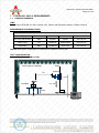
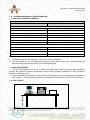
Report No.: AGC01199131101EE01 Page 6 of 48 3. TEST METHODOLOGY All tests were performed in accordance with the procedure documented in ETSI EN 301 489-1 V1.9.2 (2011-09) as referenced in ETSI EN 301 489-8 V1.2.1 (2002-08) 3.1. ANTENNA The calibrated antennas used to sample the radiated field strength are mounted on a non-conductive, motorized antenna mast 3 meters from the leading edge of the turntable. 3.2. DECISION OF TEST MODE Mode 1: operation mode 1. Mode 2: DCS 1800 Standby Mode Note: both DCS 1800 in operation mode have been tested, and the DCS 1800 mode is the worst condition as result in the test report. Report No.: AGC01199131101EE01 Page 7 of 48 4. INSTRUMENT AND CALIBRATION 4.1. MEASURING INSTRUMENT CALIBRATION The measuring equipment, which was utilized in performing the tests documented herein, has been calibrated in accordance with the manufacturer's recommendations for utilizing calibration equipment, which is traceable to recognized national standards. Report No.: AGC01199131101EE01 Page 8 of 48 5. FACILITIES AND ACCREDITATIONS 5.1. 5.2. FACILITIES Test Site: Attestation of Global Compliance (Shenzhen) Co.,Ltd. Address: 1F., No.2 Building, Huafeng No.1 Technical Industrial Park, Sanwei, Xixiang, Baoan District, Shenzhen EQUIPMENT Radiated emissions are measured with one or more of the following types of linearly polarized antennas: tuned dipole, biconical, log periodic, bi-log, and/or ridged waveguide, horn. Spectrum analyzers with preselectors and quasi-peak detectors are used to perform radiated measurements. Conducted emissions are measured with Line Impedance Stabilization Networks and EMI Test Receivers. Calibrated wideband preamplifiers, coaxial cables, and coaxial attenuators are also used for making measurements. All receiving equipment conforms to CISPR Publication 16-1, “Radio Interference Measuring Apparatus and Measurement Methods.” Report No.: AGC01199131101EE01 Page 9 of 48 6. SETUP OF EQUIPMENT UNDER TEST 6.1. SETUP CONFIGURATION OF EUT See test photographs attached in Appendix 1 for the actual connections between EUT and support equipment. 6.2. SUPPORT EQUIPMENT Device No. Brand Type RF OMMUNICATION 1. HP TEST SET Model Series No. Data Cable Power Cord 8920B -- -- -- Notes: 1. All the equipment/cables were placed in the worst-case configuration to maximize the emission during the test. 2. Grounding was established in accordance with the manufacturer’s requirements and conditions for the intended use. 6.3. TEST SETUP The equipment under test was configured and operated in a manner of normal operation. EUT tended to maximize its emission characteristics in a typical application for conducted and radiated emission measurement. The RF module plus ancillary (stand alone unit) was evaluated as per table 2 of clause 7.1 of ETSI EN 301 489-1. Software Used During the Test Operating System -- File Name -- Program Sequence -- RF Management Software -- Remark: During the test, no modification is made to the EUT to comply with Class B limit levels. Report No.: AGC01199131101EE01 Page 10 of 48 7. ETSI EN 301 489-1/-8 REQUIREMENTS 7.1. RADIATED EMISSION LIMIT Please refer to ETSI EN 301 489-1 Clause 8.2.3, Table 3 and EN 55022 Clause 6, Table 6, Class B MEASUREMENT EQUIPMENT USED Radiated Emission Test Site # 4 Name of Equipment Manufacturer Model Serial Number Calibration Due EMI TEST RECEIVER R&S ESCS30 100307 2014-07-16 AMPLIFIER HP HP8447D 2944A10419 2014-07-16 ANTENNA R&S VULB9163 9163-194 2014-07-16 Remark: Each piece of equipment is scheduled for calibration once a year. TEST CONFIGURATION Radiated Disturbance 30M to1 GHz Mast Semi-anechoic Chamber 3m Turntable 360° Antenna 1m∼4m EUT 80cm Receiver Report No.: AGC01199131101EE01 Page 11 of 48 Radiated Disturbance above 1 GHz Receiver For the actual test configuration, please refer to the related item-Photographs of the Test Configuration. Report No.: AGC01199131101EE01 Page 12 of 48 TEST PROCEDURE Please refer to ETSI EN 301 489-1 Clause 8.2.2 and EN 55022 Clause 6 for the measurement methods. TEST RESULTS Report No.: AGC01199131101EE01 Page 13 of 48 Report No.: AGC01199131101EE01 Page 14 of 48 Report No.: AGC01199131101EE01 Page 15 of 48 Report No.: AGC01199131101EE01 Page 16 of 48 7.2. AC MAINS LINE CONDUCTED EMISSION LIMIT Please refer to ETSI EN 301 489-1 Clause 8.4.3, Table 8 and EN 55022 Clause 5, Table 2, Class B MEASUREMENT EQUIPMENT USED Conducted Emission Test Site # 3 Name of Equipment Manufacturer Model Serial Number Calibration Due EMI Test Receiver R&S ESCI 1166.5950.03 2014-07-16 LISN R&S ESH3-Z5 831.5518.52 2014-07-16 Wireless Communications Test Set Agilent 8960 -- 2014-07-16 Remark: Each piece of equipment is scheduled for calibration once a year. TEST CONFIGURATION V ert. reference p lane E M I receiv er EUT LIS N R eference ground plane TEST PROCEDURE Please refer to ETSI EN 301 489-1 Clause 8.4.2 and EN 55022 Clause 5 for the measurement methods. TEST RESULTS (OPERATION MODE) Test performed on all modes,the mode 1 is the worst and recording in the following. Report No.: AGC01199131101EE01 Page 17 of 48 CONDUCTED EMISSION TEST – LINE 1 Report No.: AGC01199131101EE01 Page 18 of 48 CONDUCTED EMISSION TEST – LINE 2 Report No.: AGC01199131101EE01 Page 19 of 48 7.3. AC MAINS HARMONIC CURRENT EMISSION 7.3.1 LIMITS OF HARMONIC CURRENT Limits for Class A Equipment Harmonics Order n Max. permissible harmonic current (A) Odd harmonics 3 2.30 5 1.14 7 0.77 9 0.40 11 0.33 13 0.21 15≤n≤39 0.15×15/n Even harmonics 2 1.08 4 0.43 6 0.30 8≤n≤40 0.23×8/n NOTE: 1. According to section 5 of EN61000-3-2, the EUT is Class A equipment. 2. The above limits are for all applications having an active input power>75W. equipment with an active input power up to and including 75W. No limits apply for 7.3.2 TEST PROCEDURE 1. The EUT was placed on the top of a wooden table 0.8 meters above the ground and operated to produce the maximum harmonic components under normal operating conditions for each successive harmonic component in turn. 1. The correspondent test program of test instrument to measure the current harmonics emanated from EUT is chosen. The measure time shall be not less than the necessary for the EUT to be exercised. 7.3.3 TEST SETUP Test System EUT 80cm Report No.: AGC01199131101EE01 Page 20 of 48 For the actual test configuration, please refer to Appendix II:Photographs of the Test Configuration. 7.3.4 TEST RESULT Test Specification Test Frequency: Waveform: Classification: Test Result Harmonics Order 1 3 5 7 9 11 13 15 17 19 21 23 25 27 29 31 33 35 37 39 50Hz Sine Class A Harmonics Current (A) 0.024 0.018 0.017 0.014 0.011 0.010 0.007 0.006 0.006 0.005 0.004 0.004 0.003 0.002 0.002 0.002 0.001 0.001 0.000 0.000 Test Voltage: Test Time: Limit (A) --------------------- Harmonics Order 2 4 6 8 10 12 14 16 18 20 22 24 26 28 30 32 34 36 38 40 230Vac 2.5min Harmonics Current (A) 0.001 0.000 0.000 0.000 0.000 0.000 0.000 0.000 0.000 0.000 0.000 0.000 0.000 0.000 0.000 0.000 0.000 0.000 0.000 0.000 NOTE: 1. The active input power of the EUT is less 75 W. 2. No limits apply for equipment with an active input power up to and including 75W. Limit (A) --------------------- Report No.: AGC01199131101EE01 Page 21 of 48 AC MAINS VOLTAGE FLUCTUATION AND FLICKER LIMIT Please refer to EN 61000-3-3 MEASUREMENT EQUIPMENT USED AC MAINS FLICKER (EN 61000-3-3) Name of Equipment Manufacturer Model Serial Number Calibration Due Harmonic Emission Flicker California Instruments 500LIX-400-CTX -- 2014-07-16 Wireless Communications Test Set Agilent 8960 -- 2014-07-16 Remark: Each piece of equipment is scheduled for calibration once a year. TEST CONFIGURATION (Same as the configuration of the AC MAINS HARMONIC CURRENT EMISSIONS TEST) Ambient Condition of the Test Site Temperature 24℃ EUT AC Voltage Rating AC 230 V/50 Hz Humidity 50% EUT DC Voltage Rating N/A Pressure 990 mbar Ground Bond Resistance 0.2 Ω Tested by Mary TEST PROCEDURE Please refer to EN 61000-3-3 for the measurement methods. TEST RESULTS (OPERATION MODE(DCS 1800)) Report No.: AGC01199131101EE01 Page 22 of 48 Flicker Test Summary per EN/IEC61000-3-3 EUT: DCS Band Selective Repeater Test category: All parameters (European limits) Test date: 2013-11-15 Start time: 16:43:03 Test duration (min): 10 Data file name: unnamed Comment: Test Result: Pass (Run time) Tested by: Bart Test Margin: 100 End time: 16:53:16 Status: Test Completed Psti and limit line European Limits Time is too short for Plt plot Parameter values recorded during the test: Vrms at the end of test (Volt): Highest dt (%): Time(mS) > dt: Highest dc (%): Highest dmax (%): Highest Pst (10 min. period): Highest Plt (2 hr. period): 229.89 -0.15 0.0 0.00 0.09 0.006 0.000 Test limit (%): Test limit (mS): Test limit (%): Test limit (%): Test limit: Test limit: 3.30 500.0 3.30 4.00 1.000Pass 0.650Pass Pass Pass Pass Pass Report No.: AGC01199131101EE01 Page 23 of 48 7.4. ELECTROSTATIC DISCHARGE LIMIT Please refer to EN 61000-4-2 MEASUREMENT EQUIPMENT USED ESD test (61000-4-2) Name of Equipment Manufacturer Model Serial Number Calibration Due LIONCEL ESD-203A ESD02301005 2014-07-16 Agilent 8960 -- 2014-07-16 R&S FSU -- 2014-07-16 ELECTROSTATIC IMMUNITY TESTER Wireless Communications Test Set Spectrum Analyzer Remark: Each piece of equipment is scheduled for calibration once a year. Test Configuration Ambient Condition of the Test Site Temperature 22°C EUT AC Voltage Rating AC 230V Humidity 50%RH EUT DC Voltage Rating N/A Pressure 990 mbar Ground Bond Resistance 0.2 Ω Tested by Mary Report No.: AGC01199131101EE01 Page 24 of 48 TEST PROCEDURE Please refer to ETSI EN 301 489-1 Clause 9.3.2 and EN 61000-4-2 for the measurement methods. The EUT (Repeater) can function as both transmitter and receiver, so the evaluation of the TRptr to ESD has undergone by the following means: Trptr: An unmodulated RF signal shall be input to an RF connector which is the input to an amplifier within the EUT. The frequency shall be within the operating band of the EUT. The signal shall be monitored at an RF connector which is an output from the amplifier under test. The level of the RF signal shall be increased until the level at the output RFconnector equals the manufacturers declared maximum RF output power for a single RF carrier. The gain of the RF amplifier is the ratio, expressed in dB of the output power to the input power. The gain shall be measured before the test, and after each exposure. This test shall be performed for each RF connector which is the input to an RF amplifier. In each case, the gain of the amplifier shall be determined by measurement at an antenna connector which is one representative output from the amplifier. This may be achieved by performing one test for which the gain of all the amplifiers in the EUT is measured, or by repeating the test for each amplifier to be tested. TEST RESULTS Description of the Electrostatic Discharges (ESD) Operation(DCS 1800) Amount of Discharges Coupling Measured Gain Result (Pass/Fail) Contact Discharge See Note Pass Air Discharge N/A Pass Voltage Mini 20 / Point ±2KV, ±4kV Mini 20 / Point ±2KV, ±4kV, ±8kV Mini 20 / Point ±2KV, ±4kV Indirect Discharge HCP See Note Pass Mini 20 / Point ±2KV, ±4kV Indirect Discharge VCP See Note Pass Note: Before the test and after the test, the change of gain of an amplifier range is not more than ±1dB, which is compliant TRptr. PERFORMANCE CRITERIA Criteria requested A/ B/ C Criteria meet A/ B/ C Report No.: AGC01199131101EE01 Page 25 of 48 2 Test Points: 1 8 6 4 10 7 5 9 3 12 11 13 19 14 16 15 18 20 21 From point 1 to 22 were contact discharge. No air discharge. 17 22 Report No.: AGC01199131101EE01 Page 26 of 48 7.5. RF ELECTROMAGNETIC FIELD LIMIT Please refer to EN 61000-4-3 MEASUREMENT EQUIPMENT USED Radiated Electromagnetic Field immunity Measurement (61000-4-3) Name of Equipment Manufacturer Model Serial Number Calibration Due Signal Generator IFR 2031 73535 2014-07-16 Power Amplifier AR 150W1000 322276 2014-07-16 Power Amplifier AR 25S1G4A 321119 2014-07-16 Wireless Communications Test Set Agilent 8960 -- 2014-07-16 Spectrum Analyzer R&S FSU -- 2014-07-16 Antenna A.H. SAS-521-4 N/A 2014-07-16 Antenna EM EM-AH-10180 N/A 2014-07-16 Remark: Each piece of equipment is scheduled for calibration once a year. Test Configuration 3 meter EUT & Support Units 1.5 meter 0.8m Power Amp Signal Generator EUT Monitoring by Tested instrument PC Controller to control S.G. & PA as well as forward power Control Room Report No.: AGC01199131101EE01 Page 27 of 48 Ambient Condition of the Test Site Temperature 22°C EUT AC Voltage Rating AC 230V Humidity 50%RH EUT DC Voltage Rating N/A Pressure 990 mbar Ground Bond Resistance 0.2 Ω Tested by Curoky TEST PROCEDURE Please refer to ETSI EN 301 489-1 Clause 9.2.2, ETSI EN 301 489-5 Clause 7.2.2 and EN 61000-4-3 for the measurement methods. The EUT (Repeater) can function as both transmitter and receiver, so the evaluation of the CRptr to RF immunity field has undergone by the following means: CRptr: An unmodulated RF signal shall be input to an RF connector which is the input to an amplifier within the EUT. The frequency shall be within the operating band of the EUT. The signal shall be monitored at an RF connector which is an output from the amplifier under test. The level of the RF signal shall be increased until the level at the output RF connector equals the manufacturers declared maximum RF output power for a single RF carrier. The gain of the RF amplifier is the ratio, expressed in dB of the output power to the input power. The gain shall be measured throughout the period of exposure to the phenomenon. This test shall be performed for each RF connector which is the input to an RF amplifier. In each case, the gain of the amplifier shall be determined by measurement at an antenna connector which is one representative output from the amplifier. This may be achieved by performing one test for which the gain of all the amplifiers in the EUT is measured, or by repeating the test for each amplifier to be tested. Report No.: AGC01199131101EE01 Page 28 of 48 TEST RESULTS Description of Preliminary Test (Operation(DCS 1800)) 1 2 3 4 Freq. Range (MHz) Field Modulation Polarity Position (°) 80-1000 6V/m Yes H/V Front 1400-2700 6V/m Yes H/V Front 80-1000 6V/m Yes H/V Right 1400-2700 6V/m Yes H/V Right 80-1000 6V/m Yes H/V Back 1400-2700 6V/m Yes H/V Back 80-1000 6V/m Yes H/V Left 1400-2700 6V/m Yes H/V Left Selection for the final test Result of Final Tests (Operation(DCS 1800) and standby Mode) Freq. Range (MHz) Field Modulation Polarity Position Measured Gain Result (Pass/Fail) 1400-2700 3V/m Yes H/V Front See Note Pass 80-1000 3V/m Yes H/V Front See Note Pass 1400-2700 3V/m Yes H/V Front See Note Pass 80-1000 3V/m Yes H/V Front See Note Pass Note: Before the test, during the test and after the test, the change of gain of an amplifier range is not more than ±1dB, which is compliant CRptr. PERFORMANCE CRITERIA Criteria requested A/ B/ C Criteria meet A/ B/ C Report No.: AGC01199131101EE01 Page 29 of 48 7.6. AC MAINS FAST TRANSIENTS – COMMON MODE LIMIT Please refer to EN 61000-4-4 MEASUREMENT EQUIPMENT USED AC MAINS FAST TRANSIENTS - COMMON MODE (EN 61000-4-4) Name of Equipment Manufacturer Model Serial Number Calibration Due LIONCEL EFT-404B EFT04401011 2014-07-16 Agilent 8960 -- 2014-07-16 R&S FSU -- 2014-07-16 Electrical Fast Transient Burst Generator Wireless Communications Test Set Spectrum Analyzer Remark: Each piece of equipment is scheduled for calibration once a year. TEST CONFIGURATION EUT AC Line EFT/Burst/ Surge Generator 0.1m Support Units Non-Conductive Table Controller Computer Ambient Condition of the Test Site Temperature 24°C EUT AC Voltage Rating AC 230V/50Hz Humidity 51%RH EUT DC Voltage Rating N/A Pressure 990 mbar Ground Bond Resistance 0.2 Ω Tested by Curoky Report No.: AGC01199131101EE01 Page 30 of 48 TEST PROCEDURE Please refer to ETSI EN 301 489-1 Clause 9.4.3 and EN 61000-4-4 for the measurement methods. For TRptr, refer to sub-clause 7.5.. TEST RESULTS Results of Final Tests (Operation (DCS 1800) and Standby Mode) Impulse Frequency: 5 kHz Tr/Th: 5/50ns Burst Duration: 15ms Burst Period: 3Hz Injection Line Voltage (kV) Injected Method Measured Gain Result (Pass / Fail) Line ±1 Direct See Note Pass Neutral ±1 Direct See Note Pass Line+ Neutral ±1 Direct See Note Pass Note: Before the test and after the test, the change of gain of an amplifier range is not more than ±1dB, which is compliant TRptr. PERFORMANCE CRITERIA Criteria requested A/ B/ C Criteria meet A/ B/ C Report No.: AGC01199131101EE01 Page 31 of 48 7.7. AC MAINS SURGE LIMIT Please refer to EN 61000-4-5 MEASUREMENT EQUIPMENT USED AC MAINS SURGES (EN 61000-4-5) Name of Equipment Manufacturer Model Serial Number Calibration Due Lightning Surge Generator LIONCEL LSG-506A LSG056001010 2014-07-16 Wireless Communications Test Set Agilent 8960 -- 2014-07-16 Spectrum Analyzer R&S FSU -- 2014-07-16 Remark: Each piece of equipment is scheduled for calibration once a year. Test Configuration To AC Source Surge Immunity Test EUT & Support Units 0.8m Controller Computer Ambient Condition of the Test Site Temperature 24°C EUT AC Voltage Rating AC 230V/50Hz Humidity 51%RH EUT DC Voltage Rating N/A Pressure 990 mbar Ground Bond Resistance 0.2 Ω Tested by Mary TEST PROCEDURE Please refer to ETSI EN 301 489-1 Clause 9.8.2 and EN 61000-4-5 for the measurement methods. For TRptr, refer to sub-clause 7.5. Report No.: AGC01199131101EE01 Page 32 of 48 TEST RESULTS Results of Final Tests (Operation(DCS 1800) and Standby Mode) Voltage Waveform: 1.2/50 us Current Waveform: 8/20 us Polarity: Positive/Negative Phase angle: 0o, 90o, 180 o, 270o Coupling Line Line + Neutral Voltage (kV) Polarity Coupling Method Measured Gain Result (Pass/Fail) 1 Pos./ Neg. Capacitive See Note Pass Note: Note: Before the test and after the test, the change of gain of an amplifier range is not more than ±1dB, which is compliant TRptr. PERFORMANCE CRITERIA Criteria requested A/ B/ C Criteria meet A/ B/ C Report No.: AGC01199131101EE01 Page 33 of 48 7.8. AC MAINS RF – COMMON MODE LIMIT Please refer to EN 61000-4-6 MEASUREMENT EQUIPMENT USED AC MAINS RF COMMON MODE (EN 61000-4-6) Name of Equipment Manufacturer Model Serial Number Calibration Due SIGNAL GENERATOR IFA 2023B 202301/878 2014-07-16 AMPLIFIER AR 75A250A 302276 2014-07-16 DUAL DIRECTIONAL COUPLER AR DC2600A 302389 2014-07-16 CDN EM TEST CDN M1/32A 0201-01 2014-07-16 Wireless Communications Test Set Agilent 8960 -- 2014-07-16 Spectrum Analyzer R&S FSU -- 2014-07-16 Remark: Each piece of equipment is scheduled for calibration once a year. Test Configuration 0.1m< L <0.3m 10 cm isolation supporter EUT and Support units CDN Power Amplifier PC Controller Ground Reference Plane Ambient Condition of the Test Site Temperature 25°C EUT AC Voltage Rating AC 230V/50Hz Humidity 52%RH EUT DC Voltage Rating N/A Pressure 990 mbar Ground Bond Resistance 0.2 Ω Tested by TEST PROCEDURE mary Report No.: AGC01199131101EE01 Page 34 of 48 Please refer to ETSI EN 301 489-1 Clause 9.5.2 and EN 61000-4-6 for the measurement methods For CRptr, refer to sub-clause 7.6. TEST RESULTS Results of Final Tests (Operation (DCS 1800) and Standby Mode) Frequency Range: 0.15MHz~80MHz Frequency Step: 1% of fundamental Dwell time: 3 Sec. 80% A.M., 1000 Hz Sine wave (Voltage: 3 V) Coupling type: CDN / RF Current Probe Range (MHz) Voltage Modulation 0.15-80 3V Yes Measured Gain Result (Pass/Fail) See Note Pass Note: Before the test, during the test and after the test, the change of gain of an amplifier range is not more than ±1dB, which is compliant CRptr. PERFORMANCE CRITERIA Criteria requested A/ B/ C Criteria meet A/ B/ C Report No.: AGC01199131101EE01 Page 35 of 48 7.9. VOLTAGE DIPS AND INTERRUPTION LIMIT Please refer to EN 61000-4-11 MEASUREMENT EQUIPMENT USED VOLTAGE DIPS AND INTERRUPTIONS (EN 61000-4-11) Name of Equipment Manufacturer Model Serial Number Calibration Due Cycle Voltage Dip Simulator LIONCEL VDS-1120D VDS11200901 2014-07-16 Wireless Communications Test Set Agilent 8960 -- 2014-07-16 Spectrum Analyzer R&S FSU -- 2014-07-16 Remark: Each piece of equipment is scheduled for calibration once a year. Test Configuration To AC Source Dips/Interruption and Variations Simulator EUT & Support Units 0.8m Controller Computer Ambient Condition of the Test Site Temperature 24°C EUT AC Voltage Rating AC 230V/50Hz Humidity 51%RH EUT DC Voltage Rating N/A Pressure 990 mbar Ground Bond Resistance 0.2 Ω Tested by Curoky TEST PROCEDURE Please refer to ETSI EN 301 489-1 Clause 9.7.2 and EN 61000-4-11 for the measurement methods. For TRptr, refer to sub-clause 7.5. Report No.: AGC01199131101EE01 Page 36 of 48 TEST RESULTS Test conditions Interruption at phase angles of 0, 45, 90, 135, 180, 225, 270 and 315 degree in a 10 sec-interval. Dips / Interruption Reduction (%) Duration (ms) Voltage Dips 30% 500 Voltage Dips 60% 100 Voltage Dips 100% 10 Voltage Dips 100% 20 Voltage Interruption 100% 5000 Note: The duration with a sequence of three dips/interruptions with a minimum interval of 10 s between each test event. Results of Final Tests (Operation(DCS 1800) and Standby Mode) Voltage Dips Test Level (% UT) Reduction (%) Duration (ms) Measured Gain Criterion request Criterion meet 70 30 500 See Note C B Note: The supply voltage is restored to its nominal value as soon less than 1 minute, and measured gain change range is not more than ±1dB, which is compliant TRptr. Voltage Dips Test Level (% UT) Reduction (%) Duration (ms) Measured Gain Criterion request Criterion meet 40 60 100 See Note C B Note: The supply voltage is restored to its nominal value as soon less than 1 minute, and measured gain change range is not more than ±1dB, which is compliant TRptr Voltage Dips Test Level (% UT) Reduction (%) Duration (ms) Measured Gain Criterion request Criterion meet 0 100 10 See Note B B Note: The supply voltage is restored to its nominal value as soon less than 1 minute, and measured gain change range is not more than ±1dB, which is compliant TRptr. Report No.: AGC01199131101EE01 Page 37 of 48 Voltage Dips Test Level (% UT) Reduction (%) Duration (ms) Measured Gain Criterion request Criterion meet 0 100 20 See Note B B Note: The supply voltage is restored to its nominal value as soon less than 1 minute, and measured gain change range is not more than ±1dB, which is compliant TRptr. Voltage Interruption Test Level (% UT) Reduction (%) Duration (ms) Measured Gain Criterion request Criterion meet 0 100 5000 See Note B B Note: The supply voltage is restored to its nominal value as soon less than 1 minute, and measured gain change range is not more than ±1dB, which is compliant TRptr. Report No.: AGC01199131101EE01 Page 38 of 48 APPENDIX 1 PHOTOGRPHS OF TEST SETUP CONDUCTED EMISSION TEST SETUP RADIATED EMISSION TEST SETUP Report No.: AGC01199131101EE01 Page 39 of 48 HARMONIC AND FLICKER TEST SETUP ELECTROSTATIC DISCHARGE TEST SETUP Report No.: AGC01199131101EE01 Page 40 of 48 EFT TEST SETUP SURGE TEST SETUP Report No.: AGC01199131101EE01 Page 41 of 48 CS TEST SETUP DIPS TEST SETUP Report No.: AGC01199131101EE01 Page 42 of 48 APPENDIX 2 PHOTOGRPHS OF EUT All VIEW OF SAMPLE TOP VIEW OF SAMPLE Report No.: AGC01199131101EE01 Page 43 of 48 BOTTOM VIEW OF SAMPLE FRONT VIEW OF SAMPLE Report No.: AGC01199131101EE01 Page 44 of 48 BACK VIEW OF SAMPLE LEFT VIEW OF SAMPLE Report No.: AGC01199131101EE01 Page 45 of 48 RIGHT VIEW OF SAMPLE OPEN VIEW OF SAMPLE Report No.: AGC01199131101EE01 Page 46 of 48 INTERNAL VIEW OF SAMPLE-1 INTERNAL VIEW OF SAMPLE-2 Report No.: AGC01199131101EE01 Page 47 of 48 INTERNAL VIEW OF SAMPLE-3 INTERNAL VIEW OF SAMPLE-4 Report No.: AGC01199131101EE01 Page 48 of 48 INTERNAL VIEW OF SAMPLE-5 INTERNAL VIEW OF SAMPLE-6 ---END OF REPORT---