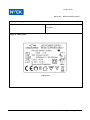
1
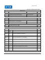
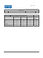
LVD TEST REPORT
Report No.: NTEK- 2012NT0713405S
Product: LED Power Supply
Model No.: ELP006C0350LT
Applicant: Eaglerise Electronics (Foshan) Co., Ltd.
Address:
No. 4, East Huanzhen Road, Beijiao, Shunde, Foshan,
Guangdong, 528000, China
Issued by: NTEK Testing Technology Co., Ltd.
Lab Location:
1/F, Building E, Fenda Science Park, Sanwei Community,
Xixiang Street, Bao’an District, Shenzhen P.R. China
Tel: (86)-0755-61156588
Fax (86)-0755-61156599
This test report consists of 29 pages in total. It may be duplicated completely for legal use with the
approval of the applicant. It should not be reproduced except in full, without the written approval of our
laboratory. The client should not use it to claim product endorsement by NTEK. The test results in the report
only apply to the tested sample. The test report shall be invalid without all the signatures of testing engineers,
reviewer and approver. Any objections must be raised to NTEK within 15 days since the date when the
report is received. It will not be taken into consideration beyond this limit.
- Page 2 of 29 -
Report No.
NTEK-2012NT0713405S
TEST REPORT
EN 61347-2-13
Part 2: Particular requirements
Section Thirteen – d.c. or a.c. supplied electronic controlgear for LED modules
Report Reference No. ..................... : NTEK-2012NT0713405S
Tested by (+ signature)...................... : Andy Huang
Approved by (+ signature) ................. : Ethan Chen
Date of issue ...................................... : 2012-07-20
Testing laboratory
Name .................................................. : NTEK Testing Technology Co., Ltd.
Address .............................................. : 1/F, Building E, Fenda Science Park, Sanwei Community, Xixiang
Street, Bao’an District, Shenzhen P.R. China
Testing location .................................. : Same as above
Client
Name .................................................. : Eaglerise Electronics (Foshan) Co., Ltd.
Address .............................................. : No. 4, East Huanzhen Road, Beijiao, Shunde, Foshan, Guangdong,
528000, China
Test specification
Standard............................................. : EN 61347-2-13:2006 conjunction with EN 61347-1:2008+A1:2011.
Test procedure .................................. : CE Attestation
Procedure deviation ........................... : N/A
Test Report Form/blank test report
Test Report Form No. ........................ : EN 61347-2-13
Test Report Form(s) Originator ........ : NTEK
Master TRF ........................................ : 08-035
Copyright reserved to the bodies participating in the CENELEC Certification Agreement (CCA).
Test item
Description ......................................... : LED Power Supply
Trademark.......................................... :
Model and/or type reference.............. : ELP006C0350LT
Rating(s)............................................. : Input: 220-240V~, 50/60Hz, 0.08A
Output: 7-20V
, 350mA
Manufacturer ...................................... : Eaglerise Electronics (Foshan) Co., Ltd.
NTEK Testing Technology Co., Ltd.
- Page 3 of 29 -
Report No.
NTEK-2012NT0713405S
Summary of testing:
Tests performed (name of test and test clause):
Testing location:
See page 2
Sample of marking plate
English label
NTEK Testing Technology Co., Ltd.
- Page 4 of 29 -
Report No.
NTEK-2012NT0713405S
Test item particulars ..............................................:
Protection against electric shock ...............................:
LED Power Supply
Supply Connection ...................................................:
Supply wire/Connector
Operating condition ..................................................:
Continuous
Classification of installation and use ........................:
Component part
Possible test case verdicts:
- test case does not apply to the test object .............:
N/A
- test object does meet the requirement...................:
P (Pass)
- test object does not meet the requirement.............:
F (Fail)
Testing .....................................................................:
Date of receipt of test item........................................:
2012-07-10
Date (s) of performance of tests...............................:
2012-07-10 to 2012-07-20
General remarks:
General product information:
LED power supply is used as a LED control gear for LED lamp.
All tests were conducted on the model ELP006C0350LT. Which with the rating as following:
NTEK Testing Technology Co., Ltd.
- Page 5 of 29 -
Report No.
NTEK-2012NT0713405S
EN 61347-2-13
Clause
Requirement − Test
4 (4)
GENERAL REQUIREMENTS
-
Compliance of independent controlgear enclosure
with EN 60598-1
P
Independent SELV controlgear comply with Annex I (see Annex I)
P
CLASSIFICATION
-
6 (6)
Result - Remark
Verdict
Independent controlgear ..........................................: Yes
No
⎯
Built-in controlgear ..................................................: Yes
No
⎯
Integral controlgear .................................................: Yes
No
⎯
SELV-equivalent or isolating controlgear.................: Yes
No
⎯
Auto-wound controlgear...........................................: Yes
No
⎯
Independent SELV controlgear................................: Yes
No
⎯
7
MARKING
-
7.1 (7.1)
Mandatory markings:
P
- mark of origin
See label
P
- model number, type reference ..............................: Refer to the model list in page
2
P
- symbol for independent controlgear, if applicable
N
- correlation between interchangeable parts and
controlgear marked
N
- rated supply voltage (V) ........................................: 220-240V~
P
- earthing symbol
N
- wiring diagram
P
- value of tc
N
- symbol for declared temperature
N
Constant voltage type:
Yes
No
⎯
- rated output voltage (V) ........................................: 7-20V, Max.25V
P
Constant current type:
⎯
Yes
- rated output current (A) .........................................: 0.35
No
P
NTEK Testing Technology Co., Ltd.
- Page 6 of 29 -
Report No.
NTEK-2012NT0713405S
EN 61347-2-13
Clause
7.2 (7.1)
Requirement − Test
Result - Remark
Verdict
- rated maximum output voltage (V) .......................: 25
P
- indication if for LED modules only
P
- information to be provided, if applicable
P
- declaration on protection against accidental
contact
See user manual for detail.
- cross-section of conductors (mm²) .......................:
- number, type and wattage of lamp(s)
P
N
For LED module only
P
- directly mains-connected windings
N
SELV-equivalent controlgear
N
Marking durable and lepgible
P
Rubbing 15 s water, 15 s petroleum; marking
legible
P
8 (10)
PROTECTION AGAINST ACCIDENTAL CONTACT WITH LIVE PARTS
-
- (10.1)
Controlgear protected against accidental contact
with live parts
P
- (A2)
The current flowing between the part concerned
Measured current:
and earth is measured and does not exceed 0,7
Max. 0.08mA;
mA (peak) or 2 mA d.c. ...........................................:
Limit:0.7mA
P
For frequencies above 1 kHz, the current does not Measured current:
exceed 0,7 mA (peak) multiplied by the value of the
Max. 1.80mA;
frequency in kilohertz or 70 mA (peak) ...................:
Limit:16.5mA(measured
frequency 23.6kHz)
P
- (7.2)
- (A2)
- (A3)
The voltage between the part concerned and any
Integral LED driver equipment
accessible part is measured and does not exceed
34 V (peak)...............................................................:
N
- (10.1)
Lacquer or enamel not used for protection or
insulation
P
Adequate mechanical strength on parts providing
protection
P
Capacitors > 0,5 μF: voltage after 1 min (V): < 50 V: The capacitor is 0.33uF
<0,5uF
N
- (10.2)
NTEK Testing Technology Co., Ltd.
- Page 7 of 29 -
Report No.
NTEK-2012NT0713405S
EN 61347-2-13
Clause
Requirement − Test
8.1 (-)
SELV-equivalent controlgear accessible parts are
insulated from live parts by double or reinforced
insulation according 8.6 and 13.1 in IEC 60065
P
8.2 (-)
Exposed terminals of SELV or SELV-equivalent
controlgear are allowed if:
P
Result - Remark
Verdict
- the rated or maximum output voltage does not
exceeding 25 V r.m.s.
- the no-load output voltage does not exceed 33 V
r.m.s. or 33 √2 V peak
Insulated terminals if rated output voltage >25 V
Insulation case
One capacitor Y1 or two capacitors Y2 of the same One approved Y1 capacitor
values used in series between SELV or SELVused
equivalent output and primary circuits
P
P
- Capacitor complying with IEC 60384-14
- Other components bridging the separating
transformer complying with IEC 60065, clause 14
9 (8)
10 (9)
TERMINALS
-
Screw terminals: compliance with Section 14 of IEC No such part
60598-1
N
Screwless terminals: compliance with Section 15 of
IEC 60598-1
N
PROVISION FOR EARTHING
-
External metal parts connected to the earthterminal:
Integral LED driver equipment
N
- compliance with 7.2.1 in IEC 60598-1
N
Test with a current of 10 A between earthing
terminal and each of the accessible metal parts;
measured resistance (Ω): < 0,5 Ω ..........................:
N
Protective earth, symbol
N
Terminal complying with clause 8 in Part 1
N
Locked against loosening and not possible to
loosen by hand
N
NTEK Testing Technology Co., Ltd.
- Page 8 of 29 -
Report No.
NTEK-2012NT0713405S
EN 61347-2-13
Clause
Requirement − Test
Result - Remark
Verdict
Not possible to loosen clamping means
unintentionally on screwless terminals
N
Earthing via means of fixing
N
Earthing terminal only used for the earthing of the
control gear
N
All parts of material minimizing the danger of
electrolytic corrosion
N
Made of brass or equivalent material
N
Contact surface bare metal
N
Conductors by tracks on printed circuit boards:
N
- a.c. current of 25 A for 1 min between earthing
terminal and accessible metal parts
N
- compliance with clause 7.2.1 in IEC 60598-1
N
MOISTURE RESISTANCE AND INSULATION
-
After storage 48 h at 91-95% relative humidity and 20-30 °C measuring of insulation
resistance with d.c. 500 V (MΩ):
P
≥ 2 MΩ for basic insulation ......................................: >100 MΩ
P
≥ 4 MΩ for double or reinforced insulation...............: >100 MΩ
P
11 (-)
Adequate insulation between input and output
terminals not bounded together in SELV-equivalent
controlgear
P
12 (12)
ELECTRIC STRENGTH
-
Immediately after clause 11 electric strength test for 1 min
P
Working voltage ≤ 42 V, test voltage 500 V
N
Working voltage > 42 V ≤ 1000 V, test voltage (V):
P
11 (11)
Basic insulation, 2U + 1000 V
1480V
Supplementary insulation, 2U + 1750 V
Double or reinforced insulation, 4U + 2750 V
No flashover or breakdown
P
N
3710V
P
P
NTEK Testing Technology Co., Ltd.
- Page 9 of 29 -
Report No.
NTEK-2012NT0713405S
EN 61347-2-13
Clause
Requirement − Test
Result - Remark
Verdict
Windings in separating transformers in SELVequivalent control gear according to 14.3.2 of
EN 60065
N
13 (13)
THERMAL ENDURANCE FOR WINDINGS (Not applicable)
⎯
14 (14)
FAULT CONDITIONS
-
When operated under fault conditions the controlgear:
-
- does not emit flames or molten material
P
- does not produce flammable gases
P
- protection against accidental contact not impaired
P
Thermally protected controlgear does not exceed
the marked temperature value
N
Fault conditions: capacitors, resistors or inductors
without proof of compliance with relevant
specifications have been short-circuited or
disconnected
- (14.1)
(see appended table)
P
Short-circuit of creepage distances and clearances
if less than specified in clause 16 in Part 1 (except
between live parts and accessible metal parts)
P
Distances on printed boards provided with coating
according to IEC 60664-3
N
- (14.2)
Short-circuit or interruption of semiconductor
devices
(see appended table)
P
- (14.3)
Short-circuit across insulation consisting of lacquer,
enamel or textile
- (14.4)
Short-circuit across electrolytic capacitors
- (14.5)
After the tests the insulation resistance with d.c.
500 V (MΩ) are ≥ 1 MΩ ............................. :
P
After the tests the accessible parts has not become >100 MΩ
live
P
During the tests, a five-layer tissue paper, where
the test specimen is wrapped, does not ignite
N
Temperature declared thermally protected
controlgear fulfil the requirements in Annex C
P
N
(see appended table)
P
NTEK Testing Technology Co., Ltd.
- Page 10 of 29 -
Report No.
NTEK-2012NT0713405S
EN 61347-2-13
Clause
Requirement − Test
15
TRANSFORMER HEATING
Windings of separating transformer in a SELVequivalent controlgear fulfil the requirements
according to 7.1 and 11.2 of IEC 60065
Result - Remark
Verdict
See temperature in table 15
P
15.1
Temperatures do not exceed the changed values of
the values in column 2 of Table 3 of IEC 60065, in
respect to relevant ambient temperature at tc, under
normal operation
P
15.2
Temperatures do not exceed the changed values of
the values in column 3 of Table 3 of IEC 60065, in
respect to relevant ambient temperature at tc, under
abnormal conditions of Cl. 16 and fault conditions
of Cl. 14
P
Ambient temperature at tc ......................... :
N
ABNORMAL CONDITIONS
-
Safety not impaired when the controlgear is
See appended table
operated at any voltage between 90% and 110% of
rated voltage
P
Control gear which are of the constant voltage output type:
⎯
a) No LED module inserted
N
b) Double LED modules or equivalent load
connected to the output terminals
N
c) Output terminal short-circuited (20 cm and
N
16
16.1
200 cm or declared length)
16.2
During and at the end of the tests no defect
impairing safety, nor any smoke or flammable
gases produced
N
Control gear which are of the constant current output type:
⎯
a) No LED module connected
P
b) Double the LED modules or equivalent load
connected in series to the output terminals
P
c) Output terminal short-circuited (20 cm and
P
200 cm or declared length )
NTEK Testing Technology Co., Ltd.
- Page 11 of 29 -
Report No.
NTEK-2012NT0713405S
EN 61347-2-13
Clause
Requirement − Test
Result - Remark
Maximum output voltage not exceeded
25V
Verdict
N
During and at the end of the tests no defect
impairing safety, nor any smoke or flammable
gases produced
P
17 (15)
CONSTRUCTION
-
- (15.1)
Wood, cotton, silk, paper and similar fibrous
material not used as insulation
P
- (15.2)
Printed boards used as internal connections
complies with clause 14 of IEC 61347-1
P
Socket-outlet in the output circuit does not accept
plugs complying with IEC 60083 and IEC 60906
18 (16)
No such parts
N
Not possible to engage plugs accepted by socketoutlet in the output circuit with socket-outlets
complying with IEC 60083 and IEC 60906
N
CREEPAGE DISTANCES AND CLEARANCES
-
Creepage distances and clearances according to
Table 3 and 4, as appropriate
(see appended table)
P
Printed boards see clause 14 of IEC 61347-1
P
Insulating lining of metallic enclosures
N
SCREWS, CURRENT-CARRYING PARTS AND CONNECTIONS
-
Screws, current-carrying parts and connections in compliance with IEC 60598-1
(clause numbers between parentheses refer to IEC 60598-1)
P
(4.11)
Electrical connections
P
(4.11.1)
Contact pressure
P
(4.11.2)
Screws:
P
- self-tapping screws
N
- thread-cutting screws
P
- at least two self-tapping screws
N
Screw locking:
P
- spring washer
P
19 (17)
(4.11.3)
NTEK Testing Technology Co., Ltd.
- Page 12 of 29 -
Report No.
NTEK-2012NT0713405S
EN 61347-2-13
Clause
Requirement − Test
Result - Remark
Verdict
- rivets
N
(4.11.4)
Material of current-carrying parts
P
(4.11.5)
No contact to wood
P
(4.12)
Mechanical connections and glands
N
(4.12.1)
Mechanical stress
P
Screws not made of soft metal
P
Screws of insulating material
N
Torque test: part; torque (Nm) ................................:
N
Torque test: part; torque (Nm) ................................:
N
Torque test: part; torque (Nm) ................................:
N
(4.12.2)
Screw diameter < 3 mm screwed into metal
N
(4.12.3)
Void
⎯
(4.12.4)
Locked connections
N
(4.12.5)
Screwed glands: force (N) ......................................:
N
20 (18)
RESISTANCE TO HEAT, FIRE AND TRACKING
-
20 (18.1)
Parts of insulating material retaining live parts in position, ball-pressure test:
P
- part; test temperature (°C) .................................:
Enclosure:1.4mm at 125℃,
Limit: 2.0mm
- part; test temperature (°C) .................................:
PCB: 0.8mm at 125℃
Limit: 2.0mm
- part; test temperature (°C) .................................:
Transformer Bobbin:1.3mm at
125℃
P
P
P
Limit: 2.0mm
20 (18.2)
Printed boards in accordance with IEC 60249-1,
4.3
20 (18.3)
External parts of insulating material preventing
electric shock glow-wire test 650 °C
20 (18.4)
P
Insulation enclosure
Transformer bobbin
P
Parts of insulating material retaining live parts in position, needle-flame test 10 s:
P
- flame extinguished within 30 s
P
Insulation enclosure
NTEK Testing Technology Co., Ltd.
- Page 13 of 29 -
Report No.
NTEK-2012NT0713405S
EN 61347-2-13
Clause
Requirement − Test
Result - Remark
- no flaming drops igniting tissue paper
Transformer bobbin
Verdict
P
20 (18.5)
Tracking test
P
21 (19)
RESISTANCE TO CORROSION
N
Rust protection:
N
- test according 4.18.1 of IEC 60598-1
N
- adequate varnish on the outer surface
N
NO-LOAD OUTPUT VOLTAGE
P
No load output voltage not differ more than 10 % from rated voltage
P
14
TABLE: tests of fault conditions
P
Part
Simulate
d fault
Result
RV1
SC
Fuse open immediately, no hazards.
NO
Q1 Pin(SG)
SC
Fuse open immediately, Q1 damaged.
NO
C1
SC
Unit shut down immediately and recoverable.
NO
T1(pin 1 to SC
pin 2)
Fuse open immediately, U1, Q1 damaged.
NO
T1(pin 3 to SC
pin 4)
Fuse open immediately, U1, Q1 damaged.
NO
T1 sec. pin
1 to 2
Unit shut down immediately and recoverable.
NO
- (20)
Hazard
C7
SC
Unit shut down immediately and recoverable.
NO
C8
SC
Unit shut down immediately and recoverable.
NO
D1
SC
Unit shut down immediately and recoverable.
NO
D3
SC
Fuse open immediately, Q1 damaged.
NO
Output
terminal
SC
Unit shut down immediately and recoverable.
NO
NTEK Testing Technology Co., Ltd.
- Page 14 of 29 -
Report No.
NTEK-2012NT0713405S
EN 61347-2-13
Clause
Requirement − Test
TABLE: 18 (16)
Result - Remark
Verdict
P
Clearance and creepage distance measurements
Cl measure (mm)
Cl limited (mm)
Cr measure (mm)
Cr limited
(mm)
L to N
4.0
2.0
4.0
2.5
Different polarity of current
fuse
3.0
2.0
3.0
2.5
Primary to Secondary of
Transformer
7.9
6.0
7.9
6.0
Y1 primary to secondary
7.8
6.0
7.8
6.0
Note: the secondary winding is used multiple insulated winding wire.
NTEK Testing Technology Co., Ltd.
- Page 17 of 29 -
Report No.
NTEK-2012NT0713405S
EN 61347-2-13
Clause
Requirement − Test
A
ANNEX A (NORMATIVE), TEST TO ESTABLISH WHETHER A CONDUCTIVE
PART IS A LIVE PART WHICH MAY CAUSE AN ELECTRIC SHOCK
-
A.2
See clause 8 A.2 in this Test Report
N
A.3
See clause 8 A.3 in this Test Report
N
C
ANNEX C – PARTICULAR REQUIREMENTS FOR ELECTRONIC LAMP
CONTROLGEAR WITH MEANS OF PROTECTION AGAINST OVERHEATING
-
C3
GENERAL REQUIREMENTS
-
C3.1
Thermal protection means integral with the
controlgear, protected against mechanical damage
N
Renewable only by means of a tool
N
If function depending on polarity, for cordconnected equipment protection means in both
leads
N
Thermal links comply with IEC 60691
N
Electrical controls comply with IEC 60730-2-3
N
C3.2
No risk of fire by breaking (clause C7)
N
C5
CLASSIFICATION
-
Result - Remark
Verdict
a) automatic resetting type
⎯
b) manual resetting type
⎯
c) non-renewable, non-resetting type
⎯
d) renewable, non-resetting type
⎯
e) other type of thermal protection; description ......:
-
C6
MARKING
-
C6.1
Symbol for temperature declared thermally
protected ballasts
N
C6.2
Declaration of the type of protection provided
N
C7
LIMITATION OF HEATING
NTEK Testing Technology Co., Ltd.
- Page 18 of 29 -
Report No.
NTEK-2012NT0713405S
EN 61347-2-13
Clause
Requirement − Test
C7.1
Preselection test
N
Test sample placed for at least 12 h in an oven
having temperature (tc - 5) K
N
No operation of the protection device
N
Functioning of protection means
N
Normal operation of the sample in a test enclosure
according to Annex D at an ambient temperature
such that (tc +0; -5) °C is obtained
N
No operation of the protection device
N
Introducing of the most onerous test condition
determined during test of clause 14
N
Output of windings connected to the mains supply
short-circuited, and other part of the controlgear
operated under normal conditions
N
Increasing of the current through the windings
continuously until operation of the protection means
N
Continuous measuring of the highest surface
temperature
N
Controlgear according to C5 a) or C5 e) operated
until stable conditions are achieved
N
Automatic-resetting thermal protectors working
3 times
N
Controlgear according to C5 b) working 6 times
N
Controlgear according to C5 c) and C5) d) working
once
N
Highest temperature does not exceed the marked
value
N
Any overshoot of 10% over the marked value within
15 min
N
ANNEX D – REQUIREMENTS FOR CARRY OUT THE HEATING TESTS OF
THERMALLY PROTECTED LAMP CONTROLGEAR
-
Tests in C7 performed in accordance with Annex D, if applicable
N
ANNEX E – USE OF CONSTANT S OTHER THAN 4500 IN tw TESTS
-
C7.2
D
E
Result - Remark
Verdict
NTEK Testing Technology Co., Ltd.
- Page 19 of 29 -
Report No.
NTEK-2012NT0713405S
EN 61347-2-13
Clause
Requirement − Test
E1
Constant S claimed
N
Claimed test method
N
Procedure A
N
Adequate data provided by the manufacturer
N
The inverse of the slope is greater than or equal to
the claimed value of S
N
Compliance with the failure criteria for procedure B
N
Procedure B
N
Claimed value of T1
N
Claimed value of T2
N
Endurance test carried out at:
N
T1 (7 samples)
N
T2 (7 samples)
N
Duration of test calculated from equation (2)
N
T1
N
T2
N
During the test:
N
E2
E3
Result - Remark
Verdict
- No open circuit
- No breakdown insulation
F
H
The claimed constant S is deemed to be verified
N
ANNEX F - DRAUGHT-PROOF ENCLOSURE
-
Draught-proof enclosure in accordance with the
description
P
Dimensions of the enclosure
N
Other design; description
N
ANNEX H - TESTS
-
NTEK Testing Technology Co., Ltd.
- Page 20 of 29 -
Report No.
NTEK-2012NT0713405S
EN 61347-2-13
Clause
Requirement − Test
Result - Remark
Verdict
All tests performed in accordance with the advise
given in Annex H, if applicable
N
I
ANNEX I - PARTICULAR ADDITIONAL REQUIREMENTS FOR INDEPENDENT
SELV D.C. OR A.C. SUPPLIED ELECTRONIC CONTROLGEAR FOR LED
MODULES
-
I.3
Classification
I.3.1
Class I
Yes
No
⎯
Class II
Yes
No
⎯
a) non-inherently short circuit proof controlgear
Yes
No
⎯
b) non-inherently open circuit proof controlgear
Yes
No
⎯
c) inherently short circuit proof controlgear
Yes
No
⎯
d) inherently open circuit proof controlgear
Yes
No
⎯
e) fail safe controlgear
Yes
No
⎯
f) non-short-circuit proof controlgear
Yes
No
⎯
g) non-open-circuit proof controlgear
Yes
No
⎯
I.3.2
I.4
⎯
Marking
-
Adequate symbols are used
N
I.5
Protection against electric shock
-
I.5.1
No connection between output winding and body
P
No connection between output winding and
protective earthing circuit
N
I.5.2
Input and output circuits electrically separated from
each other
P
I.5.2.1
Insulation between input and output winding of the
HF-transformer consists of double or reinforced
insulation
N
Class II: insulation between input/output and body
consists of double or reinforced insulation
P
Class I: insulation between input and body consists
of basic and between output and body
supplementary insulation
N
NTEK Testing Technology Co., Ltd.
- Page 21 of 29 -
Report No.
NTEK-2012NT0713405S
EN 61347-2-13
Clause
Requirement − Test
I.5.2.2
Insulation between input and output winding via the
core consists of double or reinforced insulation
P
Insulation between cord and windings of the HFtransformer consists of basic insulation
N
I.5.2.3
Serrated tape, additional layer
N
I.5.2.4
Class I controlgear for fixed connection provided
with basic insulation plus protective screening
comply with the following conditions:
N
a) Insulation between the input winding and the
protective screen complies with the requirements
for basic insulation
N
b) Insulation between the protective screen and the
output winding complies with the requirements
for basic insulation
N
c) Metal screen consists of a metal foil or of a wire
wound screen
N
d) Metal screen so arranged that both edges
cannot simultaneously touch a magnetic core
N
e) Metal screen and its lead-out wire have a crosssection sufficient to ensure that an overload
device will open the circuit before the screen is
destroyed
N
f) Lead-out wire sufficiently fixed to the metal
screen
N
Last turn of each winding of the transformer
retained by positive means
P
Impregnated winding
N
Winding held together by means of insulating
material
P
I.5.3
Components bridging between input and output
circuit
P
I.5.3.1
Used capacitors and resistors comply with 8.2
P
I.5.3.2
Used opto-couplers
N
I.6
Heating
⎯
I.6.1
No excessive temperatures in normal use
P
I.5.2.5
Used material classified as Class
Result - Remark
_____
Verdict
⎯
NTEK Testing Technology Co., Ltd.
- Page 22 of 29 -
Report No.
NTEK-2012NT0713405S
EN 61347-2-13
Clause
Requirement − Test
Result - Remark
_____
Stated value of ta
I.6.2
Verdict
⎯
Upri: 1.06 time supply rated voltage
⎯
Determined temperature rises in windings:
P
- Primary:
_73.5_ K
- Limit max:
_110_ K
- Secondary:
_65.8_ K
- Limit max:
_110_ K
After the test:
P
- no connections have worked loose
P
- no reduction of creepage distances and
clearances
P
- no flow of sealing compound
P
- no operation of protecting devices
P
- electric strength test between input and output
windings
P
I.6.3
Cycling test (10 cycles):
N
I.6.3.1
- heat run at
I.6.3.2
- moisture treatment 48 h
N
I.6.3.3
- vibration test 1 h; 1,5 g
N
I.6.3.4
After the tests:
N
- insulation resistance
N
- dielectric strength test at 35 % of specified value;
test voltage
_____ V
N
- Current or the ohmic component does not
deviates by more than 30 %
N
I.7
Short-circuit and overload protection
-
I.7.1
Upri: 1.06 times rated voltage or 0.94 and 1.06
times rated supply voltage
P
- used voltage
I.7.2
I.7.3
I.7.4
_____ K
N
__254.4_ V
Determined temperature rise in windings and on
other parts:
P
NTEK Testing Technology Co., Ltd.
- Page 23 of 29 -
Report No.
NTEK-2012NT0713405S
EN 61347-2-13
Clause
Requirement − Test
Result - Remark
- test according to Clause
Verdict
__II__
P
- Primary winding
_73.5_ K
P
- Limit max
_110_ K
P
- Secondary winding
_65.8_ K
P
- Limit max
_110_ K
P
__43.9___ K
P
80 K
P
______ K
N
60 K
N
______ K
N
- Limit max
60 K
N
- Supports
______ K
N
- Limit max
80 K
N
- External enclosure
- Limit max
- Rubber insulation of wiring
- Limit max
- PVC insulation of wiring
I.7.5
Fail-safe convertors
N
I.7.5.1
- Upri: 1.06 times rated supply voltage ............... V:
⎯
- Isec: 1.5 times rated output current ................. A:
⎯
- time until steady-state conditions t1 (h) ..............:
⎯
- time until failure t2 (h): < t1; < 5 h .......................:
N
During the test:
-
- no flames, molten material, etc.
N
- temperature rise of enclosure < 150 K
N
- temperature rise of plywood support < 100 K
N
After the test:
N
- electric strength (test voltage; 35 % of specified
value); no flashover or breakdown for primary-tosecondary and for primary-to-body
N
- live parts not accessible by test finger through
holes of enclosure
N
I.8
Insulation resistance and electric strength
-
I.8.1
Conditioned 48 h between 91 % and 95 %
P
I.8.2
Adequate insulation (500 V d.c. for 1 min) between:
-
I.7.5.2
NTEK Testing Technology Co., Ltd.
- Page 24 of 29 -
Report No.
NTEK-2012NT0713405S
EN 61347-2-13
Clause
Requirement − Test
Result - Remark
Verdict
Live parts and the body -for basic insulation not
less than 2 MΩ ....................................................... :
N
Live parts and the body -for reinforced insulation
>500 MΩ
not less than 4 MΩ ................................................. :
P
Input- and output circuits not less than 5 MΩ ........ : >500 MΩ
P
Metal parts of class II controlgear which are
separated from live parts by basic insulation only
and the body not less than 5 MΩ ........................... :
N
Metal foil in contact with the inner and outer
>500 MΩ
surfaces of enclosures of insulating material not
less than 2 MΩ ....................................................... :
P
Electric strength test:
-
1) Between live parts of input circuits and live parts 3710 V
of output circuits ................................................. :
P
2) Over basic or supplementary insulation between:
N
a) live parts which are or may become of different
polarity ................................................................ :
N
b) live parts and body if intended to be connected
to protective earth .............................................. :
N
c) accessible metal parts and a metal rod of the
same diameter as the flexible cable or cord ...... :
N
d) live parts and an intermediate metal part ........... :
N
e) intermediate metal parts and the body .............. :
N
3) Over reinforced insulation between the body and
live parts ............................................................. :
N
No flashover or breakdown occurred
P
I.9
Construction
-
I.9.1
Comply with all requirements
P
I.9.2
The distance between input and output terminals
shall not be less than 25 mm ................................. :
P
I.10
Components
-
I.10.1
Socket-outlets in the output circuit does not accept
plugs complying with IEC 60083 and IEC 60906-1
N
I.8.3
NTEK Testing Technology Co., Ltd.
- Page 25 of 29 -
Report No.
NTEK-2012NT0713405S
EN 61347-2-13
Clause
Requirement − Test
I.10.2
Self-resetting protective devices shall not be used
unless it is certain that there will be no hazards
N
Compliance is checked by connecting the
controlgear for 48 h at 1.06 times the rated voltage
with the output short-circuited
N
Creepage distances and clearances
-
1. Insulation between input and output circuits:
-
a) measured values > specified values (mm) ........ : T1 bobbin thickness:1.3
P
b) measured values > specified values (mm) ........ :
N
c) measured values > specified values (mm) ........ :
N
2. Insulation between adjacent input circuits:
measured values > specified values (mm) ........ :
N
2. Insulation between adjacent output circuits:
measured values > specified values (mm) ........ :
N
3. Insulation between terminals for external connection:
-
a) measured values > specified values (mm) ........ :
N
b) measured values > specified values (mm) ......... :
N
c) measured values > specified values (mm) ........ :
N
4. Basic or supplementary insulation:
-
a) measured values > specified values (mm) ........ :
P
b) measured values > specified values (mm) ........ :
N
c) measured values > specified values (mm) ........ :
N
5. Reinforced insulation: measured values >
specified values (mm) ........................................ :
P
6. Distance through insulation:
-
a) measured values > specified values (mm) ........ :
N
b) measured values > specified values (mm) ......... :
N
c) measured values > specified values (mm) ........ :
N
d) measured values > specified values (mm) ........ :
N
I.11
Result - Remark
Verdict
NTEK Testing Technology Co., Ltd.
- Page 26 of 29 -
Report No.
NTEK-2012NT0713405S
EN 61347-2-13
Clause
Requirement − Test
15
TABLE: Annex I.6.2 Heating test, thermocouples
Result - Remark
Model No.:
Test voltage (V)
:
Verdict
P
ELP006C0350LT
⎯
240V, 60Hz
⎯
⎯
23.7
Ambient (°C) :
Thermocouple locations
dT (K)
Max. dT (K)
240V, 60Hz
--
AC connector
33.8
--
70
CX1
43.9
--
100
L2 winding
46.1
--
130
L5 winding
51.7
--
130
PCB under IC
59.6
--
130
T1 coil
73.5
--
110
T1 core
65.8
--
110
CY1
59.1
--
100
PCB near D7
98.3
--
130
Enclosure inside near T1
62.9
--
90
Enclosure OUTside near T1
43.8
--
90
Support
54.1
--
90
Ambient
24.6
--
---
NTEK Testing Technology Co., Ltd.