1
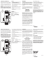
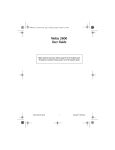
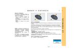
INSTRUCTION GUIDE
Wireless Extend-A-Wall Switch HW2155D
Transmitter
Switch
Receiver
Switch
RECEIVER SWITCH
Allows you to control an overhead light from 2 locations.
Warning: Turn off power first by removing the fuse or switching
the circuit breaker to “off.” This product requires some knowledge of electrical wiring and must be installed in accordance with
the National Electrical Code (NEC) and local codes.
Note: Not for use with existing three-way circuits.
1. Turn off power (see above).
2. Remove the faceplate of the existing wall switch.
3. Remove the existing wall switch.
4. Attach the green ground wire to the ground wire from the 120V
line. Connect power leads to the Receiver wires by twisting
the wire nut clockwise over the ends. Push all wiring into the
outlet box.
Note: If installed in a metal box, the green ground wire and
120V line must be grounded to the box. Refer to local or National
Electrical Code requirements.
ENCLOSED YOU WILL FIND:
• Receiver Switch
• Transmitter Switch
• Double-sided tape
• 12-Volt alkaline battery (installed)
• Wiring Device Screws and Wire Nuts (bagged)
• Screws - for mounting Transmitter Switch
TOOLS NEEDED:
• Small Flat head screwdriver
• Tweezers
ON
INSTALLATION
Four channels are available so that you can operate up to four
systems at different locations around your home. (See channel
options.)
GUIA DE INSTRUCCIONES
Interruptor Extend-A-Wall HW2155D
Transmisor de
control a distancia
Receptor
de clavijas
INCLUIDO USTED ENCONTRARA:
• Interruptor receptor
• Interruptor de transmisor
• Cinta de dos lados
• Batería alcalina de 12V (instalada)
• Tornillos de instalación y tuercas de conductores (en la
bolsa)
• Tornillos para montar el interruptor transmisor
Control
Switch
INTERRUPTOR RECEPTOR
Le permite controlar una luz elevada desde 2 ubicaciones.
Aviso: Desconecte primero la alimentación eléctrica sacando
el fusible, o poniendo el disyuntor en la posición “Off.” Este
producto requiere el tener conocimientos acerca de instalaciones
eléctricas, y se debe instalar de acuerdo con el Código Eléctrico
Nacional (NEC) y los códigos locales.
Nota: No apto para usar con los circuitos existentes de tres
direcciones.
1. Desconecte la alimentación eléctrica (vea más arriba).
2. Saque el escudete del interruptor de pared existente.
3. Saque el interruptor de pared existente.
4. Una el cable a tierra verde al cable a tierra de la línea de 120
voltios. Conecte los conductores de la alimentación eléctrica
a los conductores del receptor retorciendo la tuerca de conductores hacia la derecha sobre los extremos. Empuje toda
la cablería dentro de la caja de salida.
Nota: Si instala en una caja metálica, el cable a tierra verde y la
línea de 120 voltios deben ponerse a tierra en la caja. Consulte
HERRAMIENTAS NECESARIAS:
• Destornillador plano pequeño
• Pinzas
INSTALACION
Se encuentran disponibles cuatro canales para que usted pueda
operar hasta cuatro sistemas en diferentes ubicaciones en su
casa. (Vea las opciones de canales.)
OFF
Interruptor
de control
5. Slide the Control Switch on the Receiver Switch to the
”On” position.
6. Confirm that the channel settings on Receiver Switch
match those on the Transmitter Switch. (See Changing Digital
Code Channels for more information.)
7. Replace existing faceplate.
Note: Do not use a metallic wall plate as it will decrease the
operating range.
8. Restore power.
TEST
Position Transmitter Switch in the desired location and test
operation by pushing the top of Switch for “On” or bottom of
Switch for “Off.”
MOUNTING SWITCH TRANSMITTER
Note: Mounting Switch on a masonry or metal wall may reduce
range.
A. For tape mounting:
1. Make sure surfaces are free of dust, oil, and other substances that could affect adhesion.
2. Attach double-sided tape to back of Switch housing.
3. Press tape firmly to mounting surface.
B. For screw mounting:
1. Remove faceplate screws from cover, place back plate
where desired and mark screw locations.
2. Insert mounting screws into holes in back plate and screw
into place.
3. Replace cover and faceplate screws.
SWITCH BATTERY REPLACEMENT
1. Remove faceplate screws from cover and lift cover away from
back plate.
2. Remove old battery.
los requisitos del código sobre electricidad nacional o local.
5. Deslice el interruptor de control en el interruptor receptor a la
posición “On.”
6. Confirme que los ajustes de códigos en el interruptor receptor
coincidan con los del interruptor transmisor. (Vea “Cambio
de los Códigos Digitales” para más información).
7. Vuelva a colocar el escudete existente.
Nota: No use una placa metálica de pared puesto que
disminuirá el alcance de operación.
8. Restaure la alimentación eléctrica.
PRUEBA
Ponga el interruptor del transmisor en la ubicación deseada
y pruebe el funcionamiento presionando la parte superior del
interruptor a la posición “On” o la parte inferior del interruptor
a la posición “Off.”
INSTALACIÓN DEL INTERRUPTOR DEL TRANSMISOR
Nota: El instalar el interruptor en una pared metálica o de albañilería puede reducir el alcance.
A. Para la instalación con cinta:
1. Asegúrese de que las superficies estén libres de polvo,
aceite, y de otras substancias que puedan afectar la
adhesión.
2. Fije la cinta de dos lados a la parte posterior de la caja del
interruptor.
3. Presione firmemente la cinta a la superficie de montaje.
B. Para la instalación con tornillos:
1. Quite los tornillos del escudete de la tapa, coloque la placa
posterior donde se desea y marque las ubicaciones de
los tornillos.
2. Inserte los tornillos de montaje dentro de los agujeros en
la placa posterior y atornille en su lugar.
3. Vuelva a poner la tapa y los tornillos del escudete.
CAMBIO DE LA BATERIA DEL INTERRUPTOR
1. Saque los tornillos del escudete de la tapa y levante la tapa
3. Install new 12-volt Type A23 alkaline battery noting polarity.
4. Replace cover and screws.
MANUAL OVERRIDE
To prevent the Receiver Switch from responding to the transmitter,
slide the Control Switch on the Receiver to the “Off” position.
Note: When changing a light bulb in the fixture controlled by
the product, slide the Control Switch on the Receiver to the “Off”
position.
TROUBLESHOOTING TIPS
Problem: Nothing happens when Switch is pressed.
Suggestions:
1. Confirm that power is “On” to the fixture being controlled by
the product.
2. Verify that Control Switch on the Receiver is in the “On” position.
3. Replace bulb.
Note: When changing a light bulb in the fixture controlled by
the product, slide the Control Switch on the Receiver to the
“Off” position.
4. Check that Receiver and Transmitter are set to same channel
and are within 50 feet of each other.
5. Check battery orientation in the Transmitter Switch or try
replacing the battery.
Problem: Light sometimes turns on/off without anyone pressing Switch.
Suggestion: If another Wireless system is on the same frequency
nearby, it could accidentally trigger your system. If this happens,
change channels on the Transmitter and Receiver by following
instructions below.
de la placa posterior.
2. Saque la batería usada.
3. Instale una batería alcalina de 12 voltios tipo A23 nueva
observando la polaridad.
4. Vuelva a colocar la tapa y los tornillos.
NEUTRALIZACION MANUAL
Para prevenir que el interruptor receptor responda al transmisor,
deslice el interruptor de control en el receptor a la posición
“Off.”
Nota: Cuando cambie una bombilla en el aparato controlado
por el producto, deslice el interruptor de control en el receptor
a la posición “Off.”
CONSEJOS PARA LA SOLUCION DE PROBLEMAS
Problema: Nada ocurre cuando se presiona el interruptor.
Sugerencias:
1. Confirme que la alimentación eléctrica esté en “On” al
aparado que está siendo controlado por el producto.
2. Compruebe que el interruptor de control en el receptor esté
en la posición “On.”
3. Cambie la bombilla.
Nota: Cuando cambie una bombilla en el aparato controlado
por el producto, deslice el interruptor de control en el receptor
a la posición “Off.”
4. Compruebe que el receptor y el transmisor estén puestos en
el mismo canal y se encuentren dentro de 50 pies el uno del
otro.
5. Compruebe la orientación de la batería en el interruptor del
transmisor o trate cambiando la batería.
Problema: La luz algunas veces se enciende/apaga sin que
nadie presione el interruptor.
Sugerencia: Si otro sistema inalámbrico en la misma frecuencia
se encuentra cercano, éste puede activar accidentalmente su
sistema. Si ocurre esto, cambie los canales en el transmisor y en
CHANGING DIGITAL CODE CHANNELS (optional)
This product utilizes digital channels to send a signal from
Transmitter to Receiver. The user can change the signal if outside interference occurs. If you use other wireless products in
your home, there is a slight possibility of interference. Use the
following instructions to change the current channel setting to
a new setting.
IMPORTANT! If you change the channel combination on the
Transmitter, you must change the combination on the Receiver.
If the channel combinations do not match, the system will
Back of
Transmitter
Front of
Receiver
CODE OPTIONS
not function!
1. Turn off power to the Receiver by removing the fuse
or switching the circuit breaker to “Off.”
2. Slide the Control Switch on Receiver Switch to the “Off”
position. Locate Channel Jumpers on back of the Transmitter
Switch and on front of the Receiver.
3. Channel codes are A, B, C & D.
4. Select proper channel by moving jumpers with tweezers.
5. Slide the Control Switch on the Receiver Switch to the
”ON” position.
6. Reinstall Receiver and Transmitter Switch by following
Installation Instructions.
SPECIFICATIONS
Detection Range: Up to 50'
Maximum Load: 350W, incandescent only
Rated Voltage:
120V AC, 60 Hz
Battery:
12-volt Type A23 alkaline
For indoor use only. Do not use with existing
three-way circuits.
CHANNEL
JUMPERS
(Under plug)
CODE OPTIONS
Not Covered - Batteries, light bulbs, and other expendable items
are not covered by this warranty. Repair service, adjustment and
calibration due to misuse, abuse or negligence are not covered
by this warranty. Unauthorized service or modification of the
product or of any furnished components will void this warranty
in its entirety. This warranty does not include reimbursement for
inconvenience, installation, set-up time, loss of use, postage,
unauthorized service, or other products used in conjunction with,
but are not supplied by, Lamson & Sessions.
This device complies with Part 15 of the FCC rules. Operation is
CAMBIO DE LOS CODIGOS DE CANALES (opcional)
Este producto utiliza codigos digitales para enviar una señal
desde el transmisor al receptor. El usuario puede cambiar la
señal si ocurre interferencia exterior. Si usted usa otros productos
inalámbricos en su casa, existe una pequeña posibilidad de
interferencia. Utilice las instrucciones siguientes para cambiar
el ajuste actual del canal a un ajuste nuevo.
¡IMPORTANTE! Si usted cambia el codigo de canal en el
transmisor, usted puede cambiar el codigo en el receptor. Si el
codigo de canales no coinciden, el sistema no funcionará.
1. Desconecte la alimentación eléctrica al receptor sacando
el fusible o poniendo el disyuntor en la posición “Off.”
Parte frontal
del receptor
CONEXIONES DEL
CANAL (Debajo del
enchufe)
Interruptor de
Control
OPCIONES DEL
CÓDIGO
If the product fails due to a manufacturing defect during normal
use, return the product and dated sales receipt to the store
where purchased for replacement OR send the product and the
dated sales receipt to:
Lamson & Sessions
25701 Science Park Drive
Cleveland, OH 44122 USA
Attn: LHP Customer Service
All requests for replacement must include a dated sales receipt
(copies accepted). LAMSON & SESSIONS IS NOT LIABLE FOR
LOST PROFITS, INDIRECT, SPECIAL, EXEMPLARY, INCIDENTAL OR
CONSEQUENTIAL DAMAGES INCLUDING WITHOUT LIMITATION
ANY SUCH DAMAGES DUE TO IMPROPER WIRING OR MISUSE
OF THE PRODUCT. As some states do not allow the exclusion
or limitation of incidental or consequential damages, the above
limitation and exclusion may not apply to you.
Control
Switch
Parte
posterior del
transmisor
LIMITED WARRANTY
The product you have purchased is guaranteed against defects
in workmanship and materials for the period stated on the
package. Warranties implied by law are subject to the same
time period limitation. Some states do not allow limitations on
how long an implied warranty lasts, so this time limitation may
not apply to you.
2. Coloque el Interruptor de Control del Interruptor Receptor en
la posición “Off” (apagado). Ubique los Conexiones del Canal
en la parte posterior del interruptor transmisor y en la parte
frontal del receptor.
3. Los códigos de canal son A, B, C y D.
4. Seleccione el canal correcto desplazando las conexiones
móviles con pinzas.
5. Coloque el Interruptor de Control del Interruptor Receptor en
la posición “ON” (encendido).
6. Vuelva a instalar el interruptor del receptor y del transmisor
siguiendo las instrucciones de instalación.
ESPECIFICACIONES
Alcance de detección: Hasta 50 pies
Carga máxima:
350 W, incandescente solamente
Tensión nominal:
120 VCA, 60 Hz
Batería:
Alcalina de 12V tipo A23
Para uso interior solamente. No apto para usar con los circuitos existentes de tres direcciones.
GARANTÍA LIMITADA
Este producto que ha comprado está garantizado por el periodo
que se informa en el envase contra defectos de mano de obra y
materiales. Las garantías implícitas legales se limitan al mismo
periodo de tiempo. Algunos estados no permiten limitaciones
en el periodo de extensión de las garantías, por lo tanto, estas
limitaciones pueden no aplicarse a su caso.
Si el producto tiene una falla provocada por defectos de fabricación durante su uso normal, devuelva el producto y el recibo
de compra fechado a la tienda en donde lo compró para que
se lo sustituyan o envíe el producto y el recibo de compra
fechado a:
Lamson & Sessions
Atencíon: Servicio de cliente de LHP
25701 Science Park Drive
Cleveland, Ohio 44122 EE.UU.
Las siguientes piezas no están cubiertas por la garantía: pilas,
bombillas o focos y cualquier otra pieza fungible. Esta garantía
tampoco incluye el servicio de reparación, ajuste o calibración
debido al uso indebido o negligente. El servicio de reparación
o modificación no autorizado del producto o de cualquiera de
las piezas que se suministran invalidará la garantía en su totalidad. Esta garantía no incluye reembolso por inconveniencia,
instalación, tiempo de preparación para la puesta en marcha,
pérdida de tiempo de uso, franqueo, servicio de reparación no
autorizado u otro producto utilizado conjuntamente con éste
pero que no lo suministra Lamson & Sessions.
Todas las solicitudes de sustitución deben incluir el recibo de
compra fechado (se aceptan copias). LAMSON & SESSIONS
NO ASUME RESPONSABILIDAD POR GANANCIAS PERDIDAS,
DAÑOS INDIRECTOS, ESPECIALES, EJEMPLARES, INCIDENTALES
O PERJUICIOS DEBIDO AL USO INDEBIDO DEL PRODUCTO O LA
PREPARACIÓN INCORRECTA DE LOS CABLES. Como algunos
Estados no permiten la exclusión o limitación de los daños y
perjuicios, las limitaciones y exclusión anteriores pueden no
aplicarse a su caso.
subject to the following two conditions:
1. This device may not cause harmful interference, and
2. This device must accept any interference received, including
interference that may cause undesired operation.
This device complies with RSS-210 of Industry Canada.
ALSO AVAILABLE FROM CARLON:
• Extend-A-Chime® – lets you hear your existing wired doorbell
in remote areas of your home or yard
• Plug-in and Battery Doorbells and Chimes
• On/Off Remote Switches
• Touch and Automatic Lighting Controls
This warranty gives you specific legal rights, and you may
also have other rights which vary from state to state. If
you have questions or need further assistance, please call
Lamson & Sessions at: 1-800-346-2646 Mon. - Fri., 9 a.m.
- 4 p.m. EST.
25701 Science Park Drive
Cleveland, Ohio 44122
www.lamson-sessions.com
Made in China
©2004
0409 IS186
Este dispositivo cumple las reglas de la Comisión Federal de
Comunicaciones (FCC), parte 15. La operación está sujeta a las
dos condiciones siguientes:
1. Este dispositivo no puede causar interferencia nociva; y
2. Este dispositivo debe aceptar cualquier interferencia que
puede recibir, incluyendo interferencia que pueda causar
operación indeseable.
Este dispositivo cumple con la norma industrial RSS-210 del
Canadá.
CARLON OFRECE TAMBIÉN:
• Extend-A-Chime® – para oír la campanilla conectada existante en un área distante de la casa o del patio.
• Campanillas y carillones enchufables y a baterias
• Interruptores remotos de encendido/apagado
• Controles de iluminacion automatico y por tacto
Esta garantía le proporciona derechos legales específicos y
además puede contar con otros derechos que varían según
el estado. Si desea formular preguntas o necesita asistencia,
sírvase llamar a: Lamson & Sessions al: 1-800-346-2646 de
lunes a viernes, de 09:00. a 16:00 hs (hora del Este).
25701 Science Park Drive
Cleveland, Ohio 44122
www.lamson-sessions.com
Hecho en China
©2004
0409 IS186