1
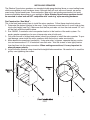
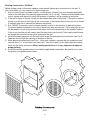
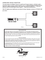
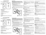
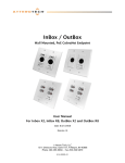
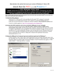
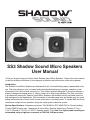
SS3 Shadow Sound Micro Speakers
User Manual
Thank you for purchasing our Dayton Audio Shadow Sound Micro Speakers. Please take a few minutes
to read the following information to insure proper installation and performance of the micro speaker.
Introduction:
The Shadow Sound Micro Speakers provide beautiful rich sound while being nearly undetectable to the
eye. The micro design is easy to conceal and are aesthetically pleasing to create a seamless sound
environment. Don’t let the small size fool you! They utilize a specially designed 3" driver that features a
powerful neodymium magnet and a ¾" Kapton voice coil for high power handling. The “Big” sound that
is produced will amaze you! Shadow Sound Micro Speakers are available in both round and square for
both ceiling and in-wall applications. All the hardware is included except wire and double gang (or round
ceiling) electrical boxes to easily install in new construction or existing homes. To achieve best results we
recommend using the micro speakers along with a high quality subwoofer system.
System Specifications: •Frequency response: 150-18,000 Hz •SPL: 88dB 1W/1m •Power handling:
15 watts RMS/35 watts max. •Impedance: 8 ohms •Micro Speaker dimensions: (Square): 5" Sq. x
1-3/4" D (Round): 5-1/2" Dia. x 1-5/8" D •Speaker weight: 2 lbs. Note: For higher power handling we
recommend using a high pass crossover at 150 Hz@ 6 dB per octave.
INSTALLING SPEAKERS
The Shadow Sound micro speakers use standard double gang electrical boxes or round ceiling boxes
which are available at most hardware stores. Although they will work with most brands, we recommend using Carlon brand boxes. Pre-construction (new work) and existing construction (old work)
boxes are available depending on your application. Note: Shadow Sound micro speakers should
be mounted in a box and are NOT compatible with “mud ring” style mounting hardware.
Pre-Construction “New Work”:
This is the best (and easiest) time to install the micro speakers. Follow these simple instructions:
1. Determine the desired location in the room. Using a hammer mount the box to a wall stud at electrical outlet height (see Fig.1) Make sure that the box protrudes out from the stud around 1/2" so it
will be flush with the drywall surface.
2. Run 18AWG, 2 conductor wire from speaker location to the location of the audio system. For
easier speaker connections, be sure to leave extra wire at both ends.
3. Only after the wall is finished and painted, should you attempt to install the micro speaker. To prevent damage, never install the micro speakers while the house is under construction.
4. Make electrical connections (see below). Using wire cutter / strippers, separate the two conductors and remove about 1/2” of insulation from each wire. Twist the strands of wire tightly before
inserting them into the crimp connectors. When making connections, it is very important to
observe proper polarity.
5. Install the micro speaker using a hand held straight blade screwdriver. Be careful not to crack the
grill by over tightening the screws.
FIG 1
(2)
Existing Construction “Old Work”:
Before cutting a hole for the micro speaker, make certain there are no obstructions in the wall. A
stud / wire finder is a very useful tool in determining this.
1. After you have found a suitable location, use the plastic “old work” box as a template and lightly
trace on the wall the cutout opening (approximately 3-3/4" x 3-3/4"). Make sure the marked cutout
area is square with the wall so when the speaker is installed it will be straight up and down.
2. If the wall is made of drywall, simply cut the marked area with a utility knife. If the wall is made of
plaster, you will need to drill holes at the four corners of the marked cutout area and use a drywall
or keyhole type saw to remove the lapboard and plaster.
3. Run 18AWG, 2 conductor wire from each speaker location to the location of the audio system.
For easier speaker connections, be sure to leave extra wire at both ends. Drill a wire hole up from
the basement or crawl space area into the interior wall cavity directly below the speaker location.
If this is not possible you will need to feed the wire down from the attic. Then simply feed the wire
up though the hole and out the cutout opening in the wall.
4. Install the double gang box into the wall cutout as per the manufactures’ instructions (see Fig.2).
Feed the wire through the opening at the back of the box.
5. Make electrical connections (see Fig.3). Using wire strippers, separate the two conductors and
remove about 1/2" of insulation from each wire. Twist the strands of wire tightly before inserting
them into the crimp connectors. When making connections, it is very important to observe
proper polarity.
6. Install the satellite speaker using a hand held straight blade screwdriver. Be careful not to crack
the grill by over tightening the screws.
FIG 2
(3)
RUNNING WIRE / MAKING CONNECTIONS
The wire between each Shadow Sound micro speaker and the home receiver or distribution panel
should be at least an 18 AWG 2 conductor cable for a 50’ run. When making connections, it is very
important to observe proper polarity. Make certain you connect the positive “+” lead to the
black wire with the white stripe and the negative “-“lead to the solid black wire.
Note: For higher power handling we recommend using a high pass crossover at 150 Hz@ 6 dB
per octave.
FIG 3
Warranty Information
Dayton Audio® products are constructed by industry experts, and are thoroughly tested before shipment.
Dayton Audio® products are warranted for the period of five years. This warranty is limited to manufacturer
defects, either in materials or workmanship. Dayton Audio® is not responsible for any consequential on inconsequential damage to any other unit or component or the cost for installation or extraction of any component
of the audio system. In the rare case of a product failure, please contact your place of purchase or call our
Customer Support Department at (937) 743-8248.
Warranty Limitations
There are no other warranties, either express or implied, which extend the foregoing, and there are no warranties
of merchantability or fitness for any particular purpose. The warranty will not cover incidental or consequential damage due to defective or improper use of products. This includes but is not limited to burnt voice coils,
overheating, bent frames, holes in the cone, or broken lead wires.
This warranty gives you specific legal rights and you may also have other rights which vary from state to state.
Non-Warranty Service: If non-warranty service is required, the product may be sent to the
Company for repair/replacement, transportation prepaid, by calling (937) 743-8248 for details,
complete instructions, and service fee charges.
daytonaudio.com
SS3-09
(4)
© 2009 Dayton Audio®