1
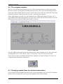
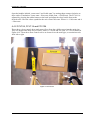
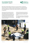
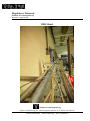
Høgskolen i Telemark
Fakultet for teknologiske fag
Bachelor i ingeniørfag
UBD Model
Fakultet for teknologiske fag
Adresse: Kjølnes ring 56, 3918 Porsgrunn, telefon 35 02 62 00, www.hit.no
Bachelorutdanning - Masterutdanning – Ph.D. utdanning
Høgskolen i Telemark
TABLE OF CONTENTS
TABLE OF CONTENTS ......................................................................................................................... 2
1
INTRODUCTION .......................................................................................................................... 3
2
PRINCIPLES ................................................................................................................................. 4
2.1 OVERBALANCED DRILLING (OBD) .......................................................................................................... 4
2.2 UNDERBALANCED DRILLING (UBD) ........................................................................................................ 4
2.3 RELATION BETWEEN UBD-MODEL AND AN OIL WELL ................................................................................. 5
3
COMMUNICATION ...................................................................................................................... 7
3.1 TRANSMITTERS ................................................................................................................................... 7
3.2 CONTROLLERS ..................................................................................................................................... 7
3.3 DELTAV ............................................................................................................................................. 7
3.4 WIRELESS HART ................................................................................................................................. 8
3.5 OPC MIRROR ..................................................................................................................................... 8
3.6 DELTAV CABINET (SKAP4100) ............................................................................................................. 9
4
CONTROLLING THE PROCESS ......................................................................................................10
4.1 STARTING THE PROGRAM .................................................................................................................... 10
4.2 THE PROGRAM INTERFACE................................................................................................................... 11
4.3 CHANGING UPDATE TIMES FOR WIRELESS TRANSMITTERS ......................................................................... 11
4.4 OPENING MANUAL WATER AND AIR VALVES ........................................................................................... 13
4.4.1 FCV154 and FCV091 ............................................................................................................... 13
4.4.2 FCV124, FCV114 and FCV104 ................................................................................................. 15
2
Høgskolen i Telemark
1 INTRODUCTION
In this user manual you will learn the basic principles behind the UBD-model, and how to
operate it from the Human Machine Interface (HMI). The model simulates underbalanced
drilling (UBD), which is a method for drilling oil by using a lower pressure than the more
commonly used overbalanced drilling (OBD). These principles are explained in chapters 2.1 and
2.2.
You will also learn what controllers and transmitters that communicate with the computer, both
wired and wireless. The different programs used in the communication process will be explained
in basics. Figure 1-1 shows the pro plus workstation.
To operate the UBD-model a basic understanding of process automation and DeltaV is
preferable. If you do not possess this, please contact your teacher to get access to the DeltaV
training station. In this guide we will not go into the programming, but you will be given
information needed to operate the model.
Figure 1-1 Pro Plus
3
Høgskolen i Telemark
2 PRINCIPLES
In this chapter the basics behind two well drilling theories will be explained, namely
Overbalanced Drilling (OBD) and Underbalanced Drilling (UBD). You will also learn how
this relates to the UBD model
2.1 Overbalanced Drilling (OBD)
OBD is the cheapest and most commonly used drilling method for well drilling since the early
20th century. This method maintains a borehole pressure that exceeds the pressure from the
exterior reservoir (shown in Figure 2-1). The OBD operates at a higher rotating speed and
therefore produces higher temperatures, and also increases the risk of formation fracture and
differential sticking. Formation fracture can cause the sides of the well to become unstable
and/or crack. Differential sticking is when the drilling head sticks to the surrounding rock
formations. This can cause an uneven drill rotation, or in worst case a total halt of the drilling.
Figure 2-1 Overbalanced drilling
2.2 Underbalanced Drilling (UBD)
Though not as commonly used as overbalanced drilling, underbalanced drilling is achieved when
the pressure exerted on the well is less than or equal to that of the reservoir (shown in Figure
2-2). Underbalanced drilling is performed with a lightweight drilling head that applies less
pressure than the formation pressure, underbalanced drilling prevents formation damage that can
occur during conventional, or overbalanced drilling procedures.
Although initially more costly, underbalanced drilling reduces common conventional drilling
problems, such as lost circulation, differential sticking and formation damage. Additionally,
underbalanced drilling extends the life of the drill because the drilling gases cool the bit by
quickly removing cuttings.
There can also be great economic advantage from the use of underbalanced drilling, in addition
to the mentioned drilling advantages. Underbalanced drilling makes it possible for the well to
produce resources while drilling, by having a lower pressure in the well. One of the risks of
using underbalanced drilling is flow back. Flow back is when the drilling fluids are not balanced
with the reservoir pressure, and can cause oil to flow uncontrollably up from the well.
4
Høgskolen i Telemark
Figure 2-2 Underbalanced drilling
2.3 Relation between the UBD-model and an oil well
As shown in Figure 2-3, the lower of the two horizontal pipes symbolizes the well (main pipe).
The upper horizontal pipe symbolizes the reservoir, where the desired hydrocarbons and gas
reside. The three vertical pipes leading down into the main pipe, simulates the flow of
hydrocarbons and gas from the reservoir into the well.
Oil and gas are simulated using a combination of air pressure and water. The water and the
pressured air flows into the main pipe causing a change in pressure, temperature and flow
volume.
Figure 2-3 UBD HMI
Figure 2-4 shows how the UBD-model relates to a real well. The flow of water and gas flows
from the reservoir into the well. In our case the well is the main pipe located on the left side.
5
Høgskolen i Telemark
Figure 2-4 Relations between UBD-model and a well
6
Høgskolen i Telemark
3 COMMUNICATION
This chapter explains what types of controllers and transmitters that are used in the automation
process for the UBD-model. There is also a basic explanation of Wireless HART and OPC
Mirror, which is used to make National Instruments signals compatible with DeltaV. The
overview of the process is shown in Figure 3-1
Process Hall
Room B-294b
SKAP4100
OPC hub
UBD Model
DeltaV Pro Plus
NI-SKAP4300
Primary hub
Instrumentation
Wireless HART
Gateway
DeltaV Controller
Secondary hub
Cable
Wireless signal
Network cable
Figure 3-1 UBD process overview
3.1 Transmitters
The transmitters used in the process:
-
22 Temperature transmitters (TT) where 2 are wireless.
5 Flow transmitters (FT).
3 Acoustic sensors (AT).
6 Pressure transmitters (PT) where 2 are wireless.
3.2 Controllers
The controllers used in the process:
-
5 Flow control valves (FCV)
8 Hand valves (HV)
3.3 DeltaV
DeltaV is the automation system used to control and monitor the UBD-model. Because this is an
advanced tutorial, the basic works of DeltaV will not be explained any further. For basic tutorials
please refer to the DeltaV training station.
7
Høgskolen i Telemark
3.4 Wireless HART
Wireless HART is Emerson Process Management´s (hereafter Emerson) own wireless system.
This system needs a wireless gateway to be able to communicate with the automation blocks that
in turn communicate with the automation HMI. In cases where the gateway, transmitters and
controllers are compatible by version, this is all you need for communication with the
automation blocks.
Wireless HART implements a masking system for communication between the individual
transmitters/controllers and the gateway. With this system in place there is no need for every
transmitter to be in direct contact with the gateway. It is sufficient that the transmitters have a
connection between them, as long as one of these transmitters are in contact with the gateway.
The transmitters and the gateway on the UBD-Model are not directly compatible. A Modbus
card is therefore needed to communicate between the gateway in the process and the DeltaV
process control. The communication between the gateway and automation blocks is established
by a network connection (Ethernet RJ-45). The gateway is located over the entrance door to
room B-294-b and is shown in Figure 3-2
Figure 3-2 Wireless Gateway
3.5 OPC Mirror
OPC mirror is a software that makes it possible to connect a wide variety of hardware to a
specified automation program. In this case OPC mirror is used for communication between
National Instruments hardware and DeltaV. In the case of the UBD-model, most of the values
are from the National Instruments (NI) cabinet shown in Figure 3-2. To make these NI values
DeltaV compatible, OPC mirror is used to “convert” between the two.
8
Høgskolen i Telemark
Figure 3-3 NI cabinet
3.6 DeltaV cabinet (SKAP4100)
In room 294-b you find cabinet SKAP4100, this is the connection point between all the signals
to/from the process. In the cabinet you will find the automation blocks (power supply, controller,
IO cards, two hubs and a network connection). The IO cards are not in use with the UBD-model,
as mentioned the model communicates through network. In SKAP4100 you will find two
network hubs, where one is used as redundancy.
9
Høgskolen i Telemark
4 CONTROLLING THE PROCESS
In this chapter we will look at the basic running of the underbalanced process. You will get
information on how to log in, open the program, using the graphical user interface (GUI).
4.1 Starting the program
Start by logging in to the DeltaV workstation in the DeltaV lab room B-294b, located in the
process hall. Start the computer labelled “pro plus”, the machine is shown in Figure 1-1. Press
“Ctrl+Alt+Delete” when prompted to open the login screen, enter user name “administrator”
and password “deltav” shown in Figure 4-1.
Figure 4-1 DeltaV Logon screen
To start the DeltaV program directly select “DeltaV Operate” from the FlexLock window to get
directly into run mode. If you want to start the program or access Windows desktop, press
“Windows Desktop” in the FlexLock window. The FlexLock window is shown in Figure 4-2.
Figure 4-2 FlexLock window
If you select “DeltaV Operate” you will be taken to the process control window in run mode. If
you select “Windows Desktop” you will be taken to a regular windows desktop. To start the
process control window from the desktop, double click the “DeltaV Operate Run” icon. Shown
in Figure 4-3.
Figure 4-3 DeltaV Operate Run icon
If you get a warning message, where part of the text is “(Typically a temporary condition.)”
select “Skip all”.
10
Høgskolen i Telemark
4.2 The program interface
There are two monitors that show the process. On the left monitor there is a basic map of how
the entire system is put together (including other processes), this is just an information monitor.
If only one of the monitors shows a picture, check if the screen cables are connected. If not, plug
both of the monitors in the back of the “pro plus” and restart the computer.
On the right monitor you will see a representation of the UBD-model shown in Figure 4-4. If
your window differs from this window, press the arrows on the top left of the screen to cycle the
different processes until the UBD-model window is shown.
Figure 4-4 UBD model
From the UBD-model window you can monitor all the values from the process. The values that
are changeable are FCV091, HV125, HV115, HV105, FCV124, FCV114, and FCV104.
If one or more values are marked with NaN (Not a Number) as shown in Figure 4-5, there is a
communication or hardware malfunction.
Figure 4-5 NaN icon
4.3 Changing update times for wireless transmitters
To save battery life, the update intervals for the wireless transmitters are set to 00.30.03 minutes.
These need to be changed in order to get faster updated values when running.
11
Høgskolen i Telemark
To access these settings, open Internet explorer. In the search window type in “http://10.4.0.7/ ” ,
this is the IP-address for the wireless gateway. When prompted select “Continue to this website
(not recommended)” to continue to the settings as shown in Figure 4-6. Press “ok” in the
following window, the user name and password are already inputted.
Figure 4-6 Wireless Gateway login
On the left side of the 1420 Wireless gateway page are a folder named setup. Press the + sign in
front to open more options. The next step is to open the HART “folder”. Press devices, here you
can change the transmit rate as shown in Figure 4-7. There are three that need to be changed,
namely PT123B, TT139B and TT145B. Choosing “next” in the HART device setup screen can
access TT145B.
12
Høgskolen i Telemark
Figure 4-7 Wireless gateway settings
Change all of the values to 00.00.03, and then press “submit”. Press “Return to form” when
prompted, after pressing submit. The transmit rate is now updated to transmit values faster.
IMPORTANT! When finished with the process change the values back to 00.30.03. The
batteries are expensive, so having slow transmits rates when not in use increase the battery life
for the wireless transmitters.
4.4 Opening manual water and air valves
Before opening the flow of water and air to the model, make sure that there is no one working on
plumbing. Before opening the valves fully, open them slightly and check for leakage. There is in
total five valves that need to be opened.
To open the “FCV” valves press the rubber button on the back of the valve. Then turn the wheel
on the front to the desired position.
4.4.1 FCV154 and FCV091
The two main valves are FCV154 and FCV091. These two valves control the air pressure and
hot/cold water to the model. These valves are located in the middle of the model, underneath the
main pipe.
13
Høgskolen i Telemark
FCV154 Controls the cold water to the process as shown in Figure 4-8. How much water you
want to flow into the process is determined on the value on the adjustment wheel (0 = Closed, 4=
Open). The red handle with a blank label sends water into FCV154, this needs to be opened
fully by turning the handle counter clockwise as far as it goes.
Figure 4-8 FCV154
On the left side of FCV154 there is a red handle on a pipe that is labeled “AIR”. This is the air
pressure. On Figure 4-8 the valve is closed. To fully open the valve, rotate the handle counter
clockwise until the handle points directly downwards.
FCV091 Controls the flow of hot or cold water to the model. Figure 4-9 shows the system
around FCV091.
Figure 4-9 FCV 091
14
Høgskolen i Telemark
Open the handles labeled “varmt vann” and “kaldt vann” by turning them counter clockwise as
done earlier (Translation: Varmt vann = Hot water, Kaldt vann = Cold Water). The FCV091 is
adjusted by pressing the rubber button on the back and adjust the wheel on the front to the
desired value. Here the values symbolize the mix of hot/cold water. Where 0 = Cold water and 4
= Hot water.
4.4.2 FCV124, FCV114 and FCV104
These three valves controls how much water flows from the cold/hot water into the main pipe.
They are adjusted the same way as earlier, where 0 = closed and 4 is open. FCV124 is shown in
Figure 4-10. These three flow control valves are located over the main pipe, at certain intervals
from left to right.
Figure 4-10 FCV124
15