1
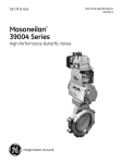
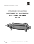
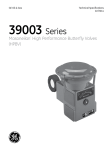
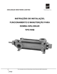
User Manual
VALVE/ACTUATOR SYSTEM
CONTENTS
SECTION 1
PRELIMINARY INFORMATION
1.1.
How to use this manual
1.2.
How to order spares
SECTION 2
ORDER, SUPPLY & SYSTEM DETAILS
2.1
Order details
2.2
Scope of supply
2.3
System drawings
SECTION 3
COMPONENT MANUALS
(Manuals for only those system components actually ordered,
marked ‘ ’ are included in this manual set)
3.1
ACTUATOR
ACT
3.2
PROCESS VALVE
VLV
3.3
SOLENOID VALVE
SOV
3.4
LIMIT SWITCH UNIT
LSB
3.5
POSITION TRANSMITTER & INDICATORS
PTR
3.6
I / P CONVERTOR
IPC
3.7
POSITIONER
POS
3.8
AIR TANK
ATK
3.9
MANUAL OVER-RIDE UNIT
MOR
3.10
OTHER PNEUMATIC ACCESSORIES
AFR
QEV
FCV ALV
NRV
ACC
3.11
PNEU. LOCK
EQV
ELC
ELECTRONIC CONTROLS
A. O. NO. :
P A G E
NUMBER
1
User Manual
VALVE/ACTUATOR SYSTEM
PRECAUTION
!
READ THIS MANUAL THOROUGHLY BEFORE ATTEMPTING TO INSTALL OR SERVICE
THIS EQUIPMENT.
!
PAY CAREFUL ATTENTION TO THE PRECAUTIONARY INSTRUCTIONS GIVEN AT
VARIOUS PLACES IN THE USER MANUALS IN OUTLINE BOXES.
SECTION 1
PRELIMINARY INFORMATION
1.1
Section 3 contains separate manuals for each
major component of the valve / actuator
systems supplied under this order. Each user
manual is complete with respect of the
system component it covers. It includes
detailed specifications, standard drawings,
and instruction, disassembly, re-assembly, and
trouble shooting.
How to use this manual
Section 1 of this manual contains instructions
relating to how to use this manual, ordering
spares.
Contact your nearest branch of our
headquarters if you require :
- Service Assistance
- Spare parts
- Actuators or valve / actuator systems
1.2
How to order spares :
Spares for El-o-matic Actuators and valve
actuator systems can be ordered through
the El-o-matic Branch office nearest to you.
Section 2 gives details which are specific to
this order: Customer's order reference, our
works reference, and scope of supply.
Drawings of the valve / actuator systems
supplied are also given in this section.
PLEASE FOLLOW PART NUMBERS AND PART NAMES ACCURATELY AS GIVEN IN THE USER
MANUALS. OTHERWISE, IT CAN LEAD TO ERRORS AND / OR DELAYS IN EXECUTING ORDERS.
SECTION : 1
INFO
P A G E
NUMBER
2
User Manual
PNEUMATIC ACTUATOR
IMPORTANT : READ THIS MANUAL THOROUGHLY BEFORE INSTALLATION OR SERVICING
CONTENTS :
1. DESCRIPTION
2. SPECIFICATIONS
3. ORIENTATION
4. AIR SUPPLY
5. OPERATION
6. MANUAL OPERATION
7. AIR CONSUMPTION
8. MAINTENANCE
9. RECOMMENDED
SPARES/REPAIR KIT
10. DISASSEMBLY
11. REASSEMBLY
12. TROUBLE SHOOTING
13. P SERIES: ACTUATOR DIMENSIONS
14. P SERIES: CONSTRUCTION, PARTS
AND MATERIALS
15. E SERIES: ACTUATOR DIMENSIONS
16. E SERIES: CONSTRUCTION
PARTS, AND MATERIALS
1. DESCRIPTION :
El-o-matic Pneumatic Actuators are pneumatic quarter
turn (90°) actuators, Special versions are available for
half turn (180°) applications. The design utilizes a
double rack and single pinion. A unique patented
features of the actuator is the application of a 3 point
support for pistons. Three carbon filled Teflon guide
bands are a balanced piston and the cylinder walls
which eliminates wear and increases the actuator life.
The bottom mounting pad of the actuator is as per ISO
5211. Thus it can be directly mounted on any valve
which conforms to ISO 5211 flange configuration.
Details relating to dimensions, assemblies, part list,
and materials are given in the drawings / data sheets in
sections 13, 14, 15 and 16.
180° actuators are available only in the' P series. (Type
PD and PE). Dimensions of 180° actuators correspond
to those of 90° actuators. Torque ratings of 180°
actuators are different.
The unit has an extended top shaft and a complete
modular design which allows simple attachment to a
variety of control accessories.
2. SPECIFICATIONS :
P SERIES
1. Pressure range
2. Torque
: PD - 0.2 to 10 bar
PE - 6 to 10 bar standard springs
PE - 3 to 10 bar, reduced springs
5. Temperature :
-20° C to + 80° C
6. Rotation
Counter-clockwise to open,
with port “ A” pressurized.
:
: 23 to 4955 Nm, at 6 bar working
pressure
Spring return actuators air
fail to close, clockwise
3. Media
: Air (dry or lubricated)
non-corrosive gas or light hydraulic oil
7. Movement
4. Construction
: Suitable for indoor or outdoor
Installation
8. Lubrication :
Actuator size (PD or PE)
Bore
Stroke
Weight
PD
PE
Operating time (standard)
Port A
Air Consumption
(actual volume at 1 atmosphere) Port B
SECTION : 3.1
:
91.5° from - 0.5 CW to
91° CCW
Factory lubricated for the
normal life of the actuator.
37.6
1100
210
50.3
2500
300
56.8
4000
325
81.7
14.0
19.2
22.4
33.4
30.8
41.5
64.7
97.9
97.8
143.0
3.4
4.2
4.8
6.0
7.0
12.0
Units
mm
mm
kg
kg
sec.
1.50
1.60
1.90
2.50
3.20
4.20
4.20
5.40
8.00
9.30
13.50
17.50
Litres
Litres
60
80
18.8
150
110
25.1
280
135
31.4
500
164
37.6
750
200
2.6
3.0
5.3
6.4
9.2
11.6
1.2
2.3
0.27
0.38
0.60
0.80
ACT
P A G E
NUMBER
1
User Manual
PNEUMATIC ACTUATOR
E SERIES
1. Pressure range
:
ED
ES
ES
:
:
:
0.2 to 10 bar
6 to 10 bar standard springs
3 to 10 bar, reduced springs
2. Torque
:
9 to 251 Nm, at 6 bar working pressure
3. Media
:
Air (dry or lubricated)
non-corrosive gas or light hydraulic oil
4. Construction
:
Suitable for indoor or outdoor
Installation
Actuator size (ED or ES)
Bore
Stroke
12
46
12.6
ED
0.61
Weight
ES
0.67
Operating time (Standard)
0.4
Air Consumption
Port A 0.05
(Actual volume at 1 atmosphere) Port B 0.06
5. Temperature
:
-20° C to +80° C
6. Rotation
:
Counter-clockwise to open with port “A”
pressurized.
Spring return actuators air fail to close,
clockwise
25
56
15.7
1.3
1.7
0.5
0.10
0.11
7. Movement
:
91.5° from -0.5° CW to 91° CCW
8. Lubrication
:
Factory lubricated for the normal life
of the actuator
40
70
18.8
2.0
2.6
0.7
0.16
0.22
3. ORIENTATION :
200
110
37.7
6.8
10.3
2.3
0.80
1.00
350
145
37.7
10.4
16.9
3.6
1.80
1.90
600
175
44.0
19.4
27.6
3.6
2.90
3.10
950
200
50.3
26.4
38.6
5.4
4.70
4.90
1600 Units
230 mm
62.8
42.7
65.8
6.9
7.30
8.00
mm
Kg
Kg
Sec
Litres
Litres
4. AIR SUPPLY :
The actuator is normally installed with its major axis
parallel to the pipeline. The actuator can be oriented
above, beside or beneath the valve without affecting its
operation.
El-o-matic actuators are factory lubricated. For
optimum operation, the use of clean, dry air / gas is
recommended. Lubricated air is not necessary.
Standard double acting actuators require 1 to 8 bar air
supply pressure and spring return actuators 3 to 8 bar.
The unique full machined shaft and square drive
mounting pattern .allows reorientation of the actuator
to accommodate installations where physical
obstructions might otherwise be prohibitive.
5. OPERA TION :
The El-o-matic actuator drive shaft rotates through a
full 90° (180° actuators are available on special order).
Rotation is accomplished by feeding supply air into the
center chamber (through port A) forcing the two
opposing pistons outward, resulting in counterclockwise rotation of the drive shaft to the 'Open'
position.
All El-o-matic actuators feature a blow out proof shaft
design. This means that the pistons must be removed
before the shaft can be reoriented.
A
A
B
ACTUATOR ASSY. MODE-A
SPRING TO CLOSE - CW
SECTION : 3.1
100
91
25.1
3.7
5.0
1.2
0.35
0.49
FIG. 1
ACT
B
ACTUATOR ASSY. MODE-D
SPRING TO OPEN - CCW
P A G E
NUMBER
2
User Manual
PNEUMATIC ACTUATOR
For double-acting actuators, closure is obtained by
feeding supply air into the end cap chambers (through
port B) which forces the pistons inward, resulting in
clock-wise rotation of the drive shaft.
All actuators are supplied with sufficient lubrication
for their normal working life. If required,
recommended lubricant for all standard actuators is
GREASE SERVOGEM 2. Consult El-o-matic for
lubricants used for high or low temperature
applications.
For spring return actuators, closure is accomplished by
means of springs contained in the end cap chambers,
which force the pistons inward when the supply air to
the center chamber (port A) is allowed to exhaust.
Depending upon the conditions under which the
actuator must work such as extended duty, noncompatible operating media, or abnormal operating
conditions, periodic replacement of internal seals is
recommended. Repair kits containing all necessary
seals can be ordered from El-o-matic.
To reverse the stroke direction of the actuator, remove
both the pistons, rotate them by 180° and re-install. This
will reverse the direction of rotation of the output shaft.
(see FIG.1).
On spring return actuators, the springs may need
replacement after extended duty, since springs may be
subject to fatigue.
6. MANUAL OPERATION :
In the event of air failure, the actuator can be cycled
manually. This is accomplished by applying a wrench to
the exposed top shaft of the actuator and turning it in the
desired direction. This is not recommended on Model
PD 500 and larger size of actuators. For these, El-omatic offers, optional Manual Override gear units, with
declutchable hand wheels. Manual wrench is not
recommended for spring return actuators.
SPRINGS SHOULD ALWAYS BE REPLACED IN
COMPLETE SETS ONLY !
Spring kits are available from El-o-matic.
9. RECOMMENDED SPARES / REPAIR KIT :
All soft seals, bearings and non-reusable parts are
included in the recommended spare part kit.
CARE MUST BE TAKEN TO ENSURE THAT THE
ACTUATOR IS NOT OPERATED
AUTOMATICALLY
THROUGH AIR SUPPLY WHILE MANUAL
OPERATION IS BEING PERFORMED!
Each kit includes:
Guide band, piston
Guide band, housing
O-rings, piston
O-rings, endcap
O-rings, shaft
Guide bush, shaft
Bearing band, shaft
Washer, shaft
Circlip, shaft
Passage O- rings
Air must be allowed to exhaust from the actuator for
manual operation. This may call for disconnecting air
lines or providing three-way vent valves at inlet ports,
depending on the pneumatic circuits.
7. AIR CONSUMPTION :
The charts showing the amount of air consumed per 90°
of stroke in litres / stroke are given in specifications
above.
The spare parts kit is identical for both the doubleacting and the spring return models. For the spring
return models, it is safe to have a set of spare springs for
each different model in addition to the recommended
spare parts kit. Keep in mind that, when necessary
springs are to be replaced in complete set.
8. MAINTENANCE :
THE ACTUATOR MUST BE ISOLATED BOTH
PNEUMATICALLY AND ELECTRICALLY BEFORE
ANY MAINTENANCE IS CARRIED OUT!
Racks are not recommended for replacement, instead,
piston-rack assemblies should be replaced, if required.
Periodic checks should be performed to make sure that
all fasteners remain tight.
SECTION : 3.1
2 nos.
1 / 2 nos.
2 nos.
2 nos.
2 nos.
1 no.
1 no.
1 no.
1 no.
2 / 4 nos.
ACT
P A G E
NUMBER
3
User Manual
PNEUMATIC ACTUATOR
10. If converting over to a 'high temperature'
actuator, or rebuilding an existing one, consult
El-o-matic for proper high temperature silicone or
graphite base grease.
10. DISASSEMBLY :
Before disassembling any actuator, be sure that the
complete repair kit is available and that the kit has been
checked for all parts.
11. REASSEMBLY :
1. Disconnect the air supply and electrical service to
the actuator.
DOUBLE ACTING ACTUATOR
1. Replace the top and bottom shaft bearings.
2. Remove the actuator from its mounting bracket.
2. Replace the shaft in the body through the bottom of
each actuator body. The bottom hole in the actuator
body is larger inside diameter than the top hole in
the body.
DISASSEMBLY AND REASSEMBLY OF THE
ACTUATOR MUST BE DONE IN CLEAN,
DUST FREE ENVIRONMENTS!
BALL VALVES AND PLUG VALVES CAN TRAP
PRESSURIZED MEDIA IN THE CAVITY.
ISOLATE THE PIPING SYSTEM IN WHICH
THE ACTUATOR VALVE ASSEMBLY IS
MOUNTED AND RELIEVE ANY PRESSURE ON
THE VALVE
3. Very carefully align the shaft square to the body.
4. Align the pinion gear so that the teeth on the center
gear will 'pick-up' the piston assembly's rack teeth,
when turning the top extension of the center gear
clockwise (CW).
3. Remove solenoid valve by unscrewing the
mounting screws. Take care to retain the solenoid
valve O-rings.
5. To ensure proper meshing of the teeth, rotate the
center gear 45° (or two teeth) counter clockwise
(CCW) from its normal position with the piston
assemblies located at the body ends. Normal
positions is that position which provides the proper
output shaft orientation required.
4. Each endcap is fitted into the body with a set of end
cap bolts. Remove all endcap bolts from both
endcaps by loosening them evenly and a little at a
time. After the screws are removed, gently pry off
each endcap being careful not to damage the
endcap O-rings.
6. With the piston assemblies in the body, gently push
each piston into the body. Turn the top shaft
extension clockwise (CW). At the proper point of
engagement between the center gear and piston
assemblies, both piston assemblies will move
toward the center of the body when turning top
shaft extension of the actuator clockwise
(CW).
IF THE ACTUATOR IS A 'SPRING RETURN’
MODE, UNIFORMLY LOOSEN ALL END CAPS .
SCREWS ON EACH END CAP TWO TO THREE
TURNS AT A TIME, IN SEQUENCE,
TO RELIEVE PRE-LOAD OF THE SPRINGS.
ON ALL ACTUATORS WITH SPRINGS, USE
CAUTION WHEN REMOVING ENDCAPS !
5. The two pistons can now be removed by rotating the
actuator shaft, driving the piston assembly outward
until the gear rack and pinion have disengaged.
7. Once the pinion gear and pistons are properly
engaged, ensure that smooth movement and 90°
operation can occur without moving the pistons out
of the actuator body. This is important.
6. Remove and discard circlip and the washer from
the shaft.
8. Take care of seal O-rings while replacing the
actuator endcaps.
7. Remove the shaft through the bottom of the body.
9. Replace the washer over the top shaft extension.
8. All repair kit O-rings, guide bands and bearings
may now be installed, if all the actuator surfaces are
clean and free of grit and scratches. If the inside
wall of the body is scored, the actuator will leak
after Rebuilding. New 'unscored' parts should be
obtained from the factory. Light tracing, barely
detectable to touch is acceptable.
10. Install the NEW circlip into its mating groove on
the top shaft extension. (The removed shaft clip is
not to be re-used). When properly installed, the
shaft clip should rotate freely within the groove.
9. Lubricate the standard actuator thoroughly with
grease Servogem 2. Apply a light film of grease to
all O-rings.
SECTION : 3.1
ACT
P A G E
NUMBER
4
User Manual
PNEUMATIC ACTUATOR
SPRING RETURN ACTUATOR :
E SERIES (Model ES).
P SERIES (Model SR)
11. When replacing spring return actuator, ensure that
the springs are replaced in their identical position in
the end cap from where they were removed.
18. When replacing ES springs in a spring return
actuator, ensure that the springs are replaced in
their identical positions in the spring pack from
where they were removed.
When less than the standard number of seven
springs are used in each end cap, these springs
should be positioned in balanced configuration
(refer FIG. 2 below)
19. If a spring return actuator is being repaired due to a
failed spring, replace ALL springs in this actuator
as well as any other parts which may have been
damaged.
20. To change springs, open the endcaps, remove nut
cover, locknut, washer and O-ring.
21. Remove the spring retaining socket bolt using a
hexagon wrench.
4 SPRINGS
6 SPRINGS
8 SPRINGS
10 SPRINGS
12 SPRINGS
14 SPRINGS
= SPRING.
22. Remove and (if necessary) replace springs as
indicated by the spring return torque chart. Be sure
that all springs are located correctly in the end cap
and the spring pack retainer. (FIG. 3)
FIG. 2
SPRING SET 1
INNER
SPRING SET 2
MIDDLE
SPRING SET 3
INNER + MIDDLE
PE SERIES ACTUATOR
12. If a spring return actuator is being repaired due to a
failed spring, replace ALL the springs in this
actuator, as well as any other parts which may have
been damaged.
SPRING SET 4
INNER + OUTER
FIG. 3
= SPRING.
13. When replacing the springs, place the actuator
body on a clean, flat surface. Position it so that it
stands on one end. Ensure that the pistons are
stroked fully inward toward the center of the
actuator. This may be done by rotating the actuator
shaft with a wrench.
ES SERIES ACTUATOR
23. Repeat steps 20 to 22 for the other spring pack.
24. Re-assemble in reverse order. (FIG. 1)
CAUTION !
14. Place the springs on the piston face, engaging them
with the bosses cast into the piston.
When spring return actuators are used in a highly
corrosive atmosphere, or when installed in the open,
there are chances of corrosive media or water entering
during suction through the silencer / breather provided
on the spring chamber port (Port 'B'). This may lead to
corrosion to springs or excessive wear and early failure
to piston sealing ring.
15. Place the endcap over the springs. Align them with
the corresponding bosses on the endcap.
16. Place the endcap bolts through the retention holes
of the endcaps.
To avoid such problems customers are advised to
use BREATHER BLOCK. Breather block avoids
suction of atmospheric air into spring chamber (Port
'B'). During spring stroke it allows air from centre
chamber (Port 'A') to fill the spring chamber and then
exhaust to atmosphere.
IF CONVERTING A DOUBLE ACTING UNIT TO
SPRING RETURN, BE SURE TO USE NEW END
CAPS.
17. Engage the bolts with the tapped holes in the
actuator body by forcing down slightly on the cap.
Tighten each bolt in SMALL and EQUAL turns.
SECTION : 3.1
SPRING SET 5
SPRING SET 6
MIDDLE + OUTER INNER + MIDDLE + OUTER
ACT
P A G E
NUMBER
5
User Manual
PNEUMATIC ACTUATOR
12. TROUBLE SHOOTING :
2. If solidified grease between the pinion and the
piston racks is present, clean, dry, regrease and
reassemble.
ACTUATOR
For identification of all numbered parts refer to
drawing numbers in sections 14 and 16.
3. Verify that the actuator pinion shaft and / or pistons
are bound. If bound, reassemble following the
rebuilding Instructions.
AN ACTUATOR SHOULD NEVER BE REMOVED
FROM THE SERVICE(PROCESSVALVE UNDER
! PRESSURE
Make sure that all internal port passages are clear and
free of any obstructions.
4. If the actuator exhibits excessive amounts of
backlash, check teeth in piston racks for wear. If
worn, replace piston gear rack assembly.
Make sure that the actuator is lubricated, and that there
is no solidified grease between the pinion and the piston
racks.
5. In spring return actuators, check for misplaced or
broken springs. If springs are broken, check the
body bore for Scoring.
1. If the actuator has no lubrication, apply generous
amounts of grease. If the actuator is for high or low
temperature operation, consult El-o-matic for
proper lubricant.
SECTION : 3.1
ACT
P A G E
NUMBER
6
User Manual
PNEUMATIC ACTUATOR
ACTUATOR SYSTEM
IMPORTANT: READ THESE GUIDELINES BEFORE ATTEMPTING ANY REPAIRS
SR.
NO.
FAULT
A.
FOR SOLENOID OPERATED
ACTUATORS :
1.
Actuator does not function.
PROBABLE CAUSE
REMEDIAL ACTION
Valve jammed / seized.
Check valve operation through
Wrench / Manual Override (MO),
if provided otherwise, remove
actuator and check valve for
smooth operation.
Excessive friction in valve gland.
Check gland packing, loosen
gland if required.
Solenoid valve not operating /
Functioning
Check solenoid coil and ensure
that specified supply voltage is
applied to coil.
Air supply not reaching actuator
Check solenoid valve operation
(listen for “click” sound).
Replace coil / valve if not
functioning.
Check pneumatic line and
connections.
Check air after regulator setting
(use local pressure. gauge for
checking supply pressure).
SECTION : 3.1
Insufficient air supply pressure
Check air supply pressure and
ensure specified air supply
pressure.
Manual Override engaged in manual
mode (where MO is mounted)
Declutch manual override and
disengage handwheel.
Equalizing valve open (if provided only for system with MO).
Check equalizing valve and close
valve fully before giving air
supply.
Speed control valve (regulating
valve) fully closed (for system with
speed control valve)
Check position of speed control
valve. Ensure that valve is kept
partially opened.
Actuator undersize for the given
application.
Cross check valve torque
requirements. Select correct size
of actuator.
ACT
P A G E
NUMBER
7
User Manual
SR.
NO.
2.
3.
FAULT
Actuator functions but
exhibits lack of power
Full stroke of actuator
not achieved
SECTION : 3.1
PNEUMATIC ACTUATOR
PROBABLE CAUSE
REMEDIAL ACTION
Leakage in pneumatic line.
Check all pneumatic connections
and tighten properly. Use Teflon
tape / thread sealants on threads.
Leakage across pistons or between
ports A & B (can happen only due to
prolonged operation over a period
of time)
Pressurise port A/B and check
for leakage from the others.
Change sealing parts if required
Low air supply pressure.
Check supply pressure and ensure
correct air supply pressure.
Severe misalignment between
actuator and valve
Check linkage. loosen mounting
bolts and align actuator correctly
for friction free rotation.
Excessive friction in gland packing
Check gland and loosen if required.
Excessive clearance / play in
adaptor / linkage
Change adaptor.
Mounting bolts loose or wrongly
Oriented
Align correctly and tighten bolts.
Limit stops on actuator (if provided,
not set correctly)
Check and reset limit stop screws
to achieve required stroke.
Limit stops on MO (incase of
systems with MO) not set properly.
Check limit stop settings on
MO and readjust if required to
achieve full rotation.
Obstruction in valve or linkage.
Check for mechanical
obstructions if any and remove
Excessive spring torque (in case of
spring return actuators). Low air
supply pressure.
Check air supply pressure
and ensure specified supply
pressure. Check spring selection.
ACT
P A G E
NUMBER
8
User Manual
SR.
NO.
4.
PNEUMATIC ACTUATOR
FAULT
Noise inside actuator
PROBABLE CAUSE
REMEDIAL ACTION
Improper clearance between rack
and pinion. Broken or loosened
rack bolts.
Open actuator and check
tightness of rack bolts. If loose
tighten properly. If worn out
replace racks /shaft.
Insufficient lubrication . (due to
prolonged use at high ambient
temperatures.)
Open actuator, clean and lubricate
with specified lubricant/grease.
Metal to metal contact due to
Replace guide bands / sealing
worn out sealing / guiding elements. elements.
B.
ACTUATORS CONTROLLED
WITH POSITIONERS
(Additional checks )
5.
Actuator not functioning on
increasing signal pressure
6.
Incorrect positioning
SECTION : 3.1
Leakage in signal line signal not
reaching Positioner.
Check signal line fittings and
tighten properly. Check for
blockage in signal line.
Insufficient supply air pressure
Check and ensure specified
air supply pressure
Faulty Positioner / seized spool
valve
Check and repair (See Positioner
instruction manual) or replace
Positioner
Feed back mechanism not
functioning / broken
Check Positioner feed back linkage
ensure positive feed back.
Excessive play in feed back
mechanism
Check linkage and connect
properly. Tighten grub screws
provided on adaptor.
Wrong span and zero adjustment.
Check span and readjust to obtain
specified span. Correct zero
Adjustment.
Wrong selection of feed back
cam profile
Check selected cam profile and
ensure that the required profile
only selected.
ACT
P A G E
NUMBER
9