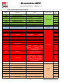
1
Technical manual Electrode steam humidifier For applications ranging from 5 to 99 kg//h Pictures for illustrating purposes only ELECTROVAP MC2 Table of Contents Safety information 3-4 Accreditation RoHS declaration 5 6 Delivery contents 7 Dimensions & weights 8 Humidifier component part overview 9 Wall installation Installation steps 10 Step 1 - Placing and wall attachement 11-12 Step 2 - Water connection 13 Step 3 - Steam pipe positioning Step 3 - Optional temperature control system Step 4 - Condensate outlet 14 to 21 22 23 Step 5 - Electrical connections 24 to 39 Step 6 - Control connection Setting up 40 41 System management Humidifier status menu 42-44 Humidifier configuration menu 45 Configuration changing menu 46-48 Maintenance Cylinder maintenance guide 49 Precaution Displayed messages 50 51 Maintenance Alerts 52 to 53 Main board changing 54 Steam cylinder cleaning Valves maintenance 55 56-57 Spares lists 58 to 61 2 Pictures for illustrating purposes only ELECTROVAP MC2 Safety information IMPORTANT Please read, heed and follow the enclosed safety information and the warning labels inside the humidifier before installation or maintenance. Warnings & safety symbols Warning : This symbol is used to designate a danger of injury or potential damage to the system. Caution : High voltages are present inside the humidifier. All works concerned with the electrical installation must be carried out by skilled and qualified personnel. Caution : Danger of scalding ! The ElectroVap MC2 generates steam during operation and therefore surfaces and pipe-work become very hot. Ensure that equipment not sustaining high temperatures be kept away. Warning : the end user should ensure that the equipment be disposed of according to the local prevailing regulations. Delivery and storage Any loss or damage during delivery should be reported to carrier by registered letter within 3 working days and be advised to devatec or to authorized dealer. It is recommended that the ElectroVap MC2 humidifier be kept in its transit packaging for as long as possible prior to maintenance. If the humidifier is to be put into storage prior to installation, it must be stored under cover and protected from physical damage, dust, frost, rain and humidity. More than 6 months storage is not recommended. 3 Pictures for illustrating purposes only ELECTROVAP MC2 Safety information GENERAL This manual contains all details necessary for the planning and installation of the ElectroVap ELMC2 humidifier. In addition commissioning and maintenance details are included. The manual is intended for use by engineers and properly trained technical personnel. Maintenance, servicing or repair work must only be carried out by suitable skilled and qualified personnel, the customer must be responsible for ensuring their suitability. Any risks or hazards, especially when working from ladders or towers should be identified by a skilled and Health and Safety representative and effective control measure put in place. No liability will attach to the Distributor if any damage, injury or accident is attributable to inattentive, inappropriate, negligent or incorrect operation of the machinery whether or not caused deliberately. Always isolate all electrical and water supplies before commencing any maintenance. Every effort has been made to ensure details contained in this manual are correct, however, in view of the wide range of conditions experienced in air handling systems, the information provided should only be used as a guide. Please contact your Agent if any doubt. Correct use ElectroVap MC2 humidifiers are ONLY intended for use with air handling systems or direct air humidification. ANY OTHER APPLICATION IS NOT CONSIDERED USE FOR THE INTENDED PURPOSE. THE MANUFACTURER CANNOT BE MADE LIABLE FOR ANY DAMAGE RESULTING FROM INCORRECT USE. Water ElectroVap MC humidifiers are designed to be used with mains, demineralized R/O or softened water. On no account attempt to introduce any other fluid or chemical into the system. Water supply should not exceed 6.0 bar and installation should comply with local regulations. If the water pressure exceeds 6.0 bar, a water regulator valve must be used. Electricity All work concerned with electrical installation MUST only be performed by skilled and qualified technical personnel (eg electrician or technicians with appropriate training). The customer MUST be responsible for ensuring their suitability. It is the duty of the installer to ensure that suitable sized cables and MCB protection is provided. Please observe the local regulations concerning the provision of electrical installations. Warranty A two year warranty term—materials and workmanship—is applicable to the parts of the ElectroVap MC2 to the exception of the consumable parts (valves, cylinders or parts of cylinders) provided our recommendations of use & maintenance have been adhered to. Failure to specify and fit original parts and accessories will invalidate our warranty. NOTE The manufacturer’s policy is one of continuous research and development. He therefore reserves the right to amend without notice the specifications given in this document. The photographs are for illustrating purposes only. 4 Pictures for illustrating purposes only ELECTROVAP MC2 Product accreditation APPLIED DIRECTIVES Electromagnetic Compatibility Directive : Low Voltage Directive : Machinery Directive : 89/336/EEC, 2004/108/EC 73/23/EEC, 2006/95/EC 98/37/EC Amending Directive 89/392/EEC Standard(s) to which Conformity is declared : EN 61000-6-3 : Electromagnetic compatibility generic requirements (residential, commercial and light industries) EN 55022 class B conducted and radiated emission limits) EN 61000-6-2 : Electromagnetic compatibility (EMC) – Generic standards –Immunity for industrial environments; EN 61000-4-3 : Radiated, radio frequency, electromagnetic field immunity test. EN 61000-4-6 : Immunity to conducted disturbances induced by radio frequency fields EN 61000-4-4 : Electrical fast transient/burnt immunity test EN 61000-4-5 : Surge immunity test EN 61000-4-2 : Electrostatic discharge immunity test EN 60204-1 : Safety of machinery – Electrical Equipment of machines – Part 1 : General requirements EN 292 Parts 1 & 2 : Safety of machinery basic principle mechanical design. Manufacturer’s Name and Address DEVATEC SAS Rue Saint Eloi 76550 Ambrumesnil - FRANCE Authorised Representative Type of equipment ELECTROVAP MC Model Name (s) & Series: ELMC Year of Manufacture 2001 We the undersigned, hereby declare that the equipment specified above conforms to the above Directive(s) and Standard(s). Mr FRAMBOT Jean-François Managing Director Date : 02.07.2007 5 Pictures for illustrating purposes only ELECTROVAP MC2 RoHS declaration devatec sas Rue Feu St Eloi 76550 Ambrumesnil France Confirms that the ElectroVap ELMC steam humidifier is manufactured in compliance with the European regulations 2002/95/EU (RoHS). This guideline regulates after July 1st 2006 the use of mercury, cadmium, lead (soldering processes), chrome VI as well as PBB and PBDE. ELMC steam humidifiers manufactured previously to this date may contain above materials. Name : MINFRAY Jean-Marie Position : R&D Engineer Date : 05.06.2008 Signature: 6 Pictures for illustrating purposes only ELECTROVAP MC2 Delivery contents Any loss or damage during delivery should be reported to carrier by registered letter within 3 working days and be advised to devatec or to authorized dealer. It is recommended that the ElectroVap MC2 humidifier be kept in its transit packaging for as long as possible prior to maintenance. If the humidifier is to be put into storage prior to installation, it must be stored under cover and protected from physical damage, dust, frost, rain and humidity. More than 6 months storage is not recommended. What is in the box : 1. One ElectroVap ELMC2 steam humidifier supplied with one, two or three disposable or cleanable cylinder(s) according to the purchased model together with an on/off or proportional control. 2. One 500mm long flexible hose with 3/4” thread (with washers) for tap water connection. 3. Ø 25 mm drain hose : ELMC 1 cylinder : 1 m. long ELMC 2 cylinders : 2 hoses of 1 m. long and 1.2 m. long respectively ELMC 3 cylinders : 3 hoses of 1 m. long, 1.2 m. long and 1.8 m. long 4. Hose clamps : ELMC 1 cylinder : 3 clamps (2 pieces for the steam hose & 1 piece for the drain hose) ELMC 2 cylinders : 6 clamps (4 pieces for the steam hoses & 2 pieces for the drain hoses) ELMC 3 cylinders : 9 clamps (6 pieces for the steam hoses & 3 pieces for the drain hoses) 3 1 7 2 4 Pictures for illustrating purposes only ELECTROVAP MC2 Dimensions & Weight 533,4 A 469 E 357 E 414,31 21C4,5 ELMC 1 small cyl. B ELMC 1 large cyl. D 262 G 357 F 300,61 D ,5 271 G4 41 F 275,22 E,69 401 ELMC 2 cylinders F 275,22 E,78 381 ELMC 3 cylinders H 300 G 402 H 275 H 275 G 382 D 552 D 521 Dimensions in mm Humidifier Model Weight in Kg Water inlet Steam outlet Steam outlet spacing Drain outlet Drain outlet spacing F G H Empty Operating A B C D E ELMC 1 SM CYL 475 540 217 215 355 355 15 23 ELMC 1 LG CYL 550 680 272 270 410 410 22 37 ELMC 2 CYL 845 680 272 270 400 300 400 300 30 60 ELMC 3 CYL 1075 680 272 270 380 275 380 275 45 90 SM CYL = small cylinder, LG CYL = large cylinder 8 Pictures for illustrating purposes only ELECTROVAP MC2 Humidifier component parts ELMC 5-30 humidifier split view 21 1 3 22 14 10 3 20 13 19 18 12 5 17 6 7 16 11 15 8 1 Steam hose 2 Water feed hose 12x16mm 3 Hose clamp 16x25mm 4 Overflow water hose 18x22m 5 On/off rocker switch 6 Stand-by lamp 7 Grommet 8 Drain cup (upper) 9 Water inlet valve 10 LCD display board (Ref 500600) 11 Remote information board (option) 12 Power contactor 13 Main circuit board 14 Filling cup 15 Drain valve 16 Cylinder strainer 17 Steam cylinder 18 Stainless steel electrode plate 19 High water level electrode 20 High water level electrode cable 21 Electrode live power cable 22 Cylinder water feed hose 18x22 mm 23 Flexible water feed hose 3/4” F 24 Hose clamp 12x22 mm 2 24 9 23 9 Pictures for illustrating purposes only ELECTROVAP MC2 Installation steps All works concerned with electrical installation must be carried out by a skilled and qualified personnel. Please read, heed and follow the enclosed information for the installation of the humidifier and the steam, water and electrical networks. For further technical assistance, feel free to call devatec. Failure to adhere to manufacturer’s installation recommendations will invalidate your warranty. Steps Setp 1 - Placing and wall attachment Step 2 - Water connection Step 3 - Steam pipe positioning Step 4 - Condensate outlet Step 5 - Electrical connection Step 6 - Control connection Step 3 Step 4 Step 1 Steps 5- 6 Step 4 Step 2 10 Pictures for illustrating purposes only ELECTROVAP MC2 Installation - Step 1 How to install the humidifier on wall Installation tips : The humidifier should be operated within 5°C and 40°C in a room with less than 80% of humidity. When in operation, the rear panel becomes hot (60°C) so do not hang the humidifier on a heat sensitive surface. The devatec humidifiers have been developped to be hanged on wall. Before installation, make sure that the surface material is strong enough to hold the humidifier. The best performances of the humidifier are achieved when the steam discharge is made at short distance from the humidifier (see after page n°20). 500 mmmini Consider free space around the humidifier to allow easy access for maintenance purposes (s.a. here under sketches). 600 mmmini 1250 mm 1000 mmmini 600 mm 11 Pictures for illustrating purposes only ELECTROVAP MC2 Installation - Step 1 Installation on wall Nota : Use installation equipment and material appropriate to the surface on which the unit should be hanged . The dimensions mentioned underneath are for cabinets without doors. Method: Mark and drill the mounting holes for 6 mm screws (s.a. the drilling distance table) : ELMC 1 & 2 cylinders : 4 mounting screws—ELMC 3 cylinders : 5 mounting screws Insert pegs in holes and the upper screws. Allow about 10 mm for hanging the cabinet. Hang the cabinet and level it vertically and horizontally. Screw up the upper screws and then screw up the lower screws. A 41 A 41 C 467 B A 41 C 455 110 110 A 41 B D 535 ELMC 3 CYL 525 525 ELMC 1 & 2 CYL H H 2x 2x O O 40 40 E E F 21 21F CYL = cylinder R4 Drilling distances in mm Model A B C ELMC 1 SM CYL 21 110 ELMC 1 LG CYL 41 ELMC 2 CYL ELMC 3 CYL D E F G H 425 40 21 425 385 110 467 40 21 507 525 41 110 760 40 21 800 525 41 110 455 40 21 1030 525 535 R6 20 10 G 1030 6 6 G 507 DETAIL A Detail of hanging hole SM CYL = small cylinder, LG CYL = large cylinder Optionnal support legs to be used for ground installations when a wall installation cannot be made. Part nb 999989 for ELMC small single cylinder model - Part nb 999992 for ELMC large single cylinder model - Part nb 999990 for ELMC two cylinder model - Part nb 999988 for ELMC three cylinder model 12 Pictures for illustrating purposes only ELECTROVAP MC2 Installation - Step 2 WATER CONNECTION Recommendations : The operating principle of the electrode steam humidifier is the electrolyse where an electrical current runs through stainless steel electrode plates immersed in water made conductive by the mineral salts it contains. The water level must be between « a » and « b » for the maximum capacity of the cylinder. b a The ElectroVap humidifier can produce steam from 3 water qualities having the following characteristics : Town water or raw water : the water TH should be between 0 and 40° French grade for a conductivity between 350µS and 1000µS/cm (Micro Siemens per centimetre). Softened water: water treated by sodium/calcium permutation on resins. The titration value TH should be kept as constant as possible and between 0° and 2°. It is essential that the salt maintenance of softeners be programmed for the water volume consummed in order to prevent an excessive salt concentration to humidifer once the regeneration cycle is finished (please refer to the softener’s user manual). Duplex softeners are best suited to your humidifier in this regard. In doubt, please consult devatec. Demineralised water: this is a water treatment by reverse osmosis or running through resins. The ElectroVap humidifier can work with demineralised waters having a minimum water quality of 30µS/cm. A tea spoon of bicarbonate of soda must be added on start-up to initiate steam production. Nota Bene : on starting up the humidifier, the nominal steam production is reached after one or two days when using low conductivity waters. This period can be shortened by adding a tea spoon of salt that has been firstly diluted in 1/4 litre of water. Pour the mixture into the filling cup. Caution : do not touch the water - Risk of electric shock. THIS MUST BE CARRIED OUT BY A SKILLED AND QUALIFIED PERSONNEL. No chemical agent whatsoever (chlorine, disinfectant, ozone… ) must be added to the water. Some water qualities may generate foam that can disturb the correct functionning of the humidifier. If this occurs to your humidifier, please refer to devatec for further assistance. Recommendations on water tapping : A fresh mains cold water service should be used to supply the unit. The water pressure should not exceed 6 bar and should not be inferior to 1 bar with a temperature less than 40°C. In case the water pressure exceeds 6 bar, a water regulator valve must be used. The water supply connection is on the bottom of the unit. All the ELMC are supplied with a 500 mm long water inlet hose with a 3/4” female connection to the cold water supply. A check valve should be located on the mains and cold water service connection to the unit. The ELMC humidifier uses water to produce steam so leakage may happen causing potential damage. If an installation in false ceiling or above prime rooms such as museum, exhibition or laboratory rooms is considered, ensure that the floor below the humidifier is constructed from waterproof materials (with draining facilities) to withstand any water spilling during servicing or if a problem occurs. 13 Pictures for illustrating purposes only ELECTROVAP MC2 Installation - Step 3 STEAM DISTRIBUTION PIPE Steam from the cylinder enters the duct via a steam distribution pipe. In order to obtain optimum performance of the humidifier, it is recommended that these instructions be adhered to as far as possible. O25 OU 40 There are two steam inlet diameters available : Ø 25 mm and Ø 40 mm L 590 1 50 8 2 2 2 1 Steam inlet 2 Condensate drain Steam distribution pipe selection table The number of distribution pipes and the diameters depend on the humidifier model. ELMC Model 1 SM CYL 1 LG CYL 2 CYL 3 CYL 1 1 2 3 Steam inlet diameter (1) Ø 25mm Ø 40mm Ø 40mm Ø 40mm Condensate drain diameter (2) Ø 8mm Ø 8mm Ø 8mm Ø 8mm Number of steam pipe(s) • SM CYL = small cylinder, LG CYL = large cylinder To get the best steam distribution, select the longest possible distribution pipe to fit the duct. Standard distribution pipes are available on either diameter in 110, 290, 590, 790, 1000, 1250 and 1500 mm long. 14 Pictures for illustrating purposes only ELECTROVAP MC2 Installation - Step 3 POSITIONING OF THE STEAM DISTRIBUTI0N PIPE Evaporation distance or vapor trail « D » A certain length is required so that the steam coming out of the steam distribution pipe be absorbed by the air. All along this length, descrided as the evaporation distance, the steam can still be seen in the airflow as a mist which can condensate in water against any obstacle if placed within. To prevent condensation, this evaporation distance should be calculated before positioning the steam distribution pipe. How to calculate the evaporation distance « D » In order to determine the evaporation distance, the attached calculation table can be used : HR1 = relative humidity of air before humidification in %. HR2 = relative humidity of air after humidification in %. % RH1 inlet air 5 10 20 30 40 50 60 70 Minimum humidification distance « D » in m. % HR2 outlet air 40 0.9 0.8 0.7 0.5 - - - - 50 1.1 1 0.9 0.8 0.5 - - - 60 1.4 1.3 1.2 1 0.8 0.5 - - 70 1.8 1.7 1.5 1.4 1.2 1 0.7 - 80 2.3 2.2 2.1 1.9 1.7 1.5 1.2 0.8 90 3.5 3.4 3.2 2.9 2.7 2.4 2.1 1.7 D minimum humidification distance in meters (m). Before / after fan D before / after heater/filter 1.5 x D D 5cm 2,5 x D before thin particule filter 15 Pictures for illustrating purposes only ELECTROVAP MC2 Installation - Step 3 Before a junction D Before / after a constriction before an air opening D 5xD before an expansion 0,5 x D 0,5 x D leve before a humidity sensor before a bend D A high humidity limit humidistat must be installed in the duct to stop the humidifier in case the level of humidity exceeds the preset value. In case the recommended distances cannot be met, please contact devatec or their authorized A agent for an alternative solution. If accurate values cannot be reached, a distance of 2 m. should be considered as a minimum distance between pipes & obstruction and 3 / 4 m. before sensor or humidistat. 16 Pictures for illustrating purposes only ELECTROVAP MC2 Installation - Step 3 STEAM DISTRIBUTION PIPE POSITIONING Please meet the following dimensions and spaces according to your configuration. For further information, please contact devatec or their authorized agent. 1 H3 H3 H > 550 mm 1 H > 410 mm H > 270 mm H1 = 110mm = Minimum height between the duct floor and the axle of the steam pipe. H2 = 140mm = Minimum distance between two pipes. H3 = 160mm = Minimum height between the duct top and the axle of the steam pipe. The H3 distance can be 80 mm at the shortest in case the steam pipe is installed at an angle of 30°. The arrow shows the direction of the air flow. 19,61 1 H3 H2 1 H2 8,51 H1 1 H2 1 1 H1 H> 480 mm H1 H> 660 mm 1 H3 1 H3 H2 1 1 H2 1 1 H2 H1 1 H1 17 Pictures for illustrating purposes only ELECTROVAP MC2 Installation - Step 3 30 3° 0à° 4 5° STEAM DISTRIBUTION PIPE POSITIONING 15° 1 H3 In vertical ducts where the air flow is upward or downward, the steam distribution pipe(s) must be tilted by 15° sideways. In duct with limited height, the distribution pipe(s) can be tilted by 30° to get the 80 mm minimum height. 590 d 47,2 d/2 D1 d = Duct diameter D = Humidification distance EXPRESSPACK The Armstrong ExpressPack is a bespoke steam humidification system made to suit your your configuration and ready to install in a ventilation duct. It permits to have vapor trails (evaporation distance) as short as 600 mm. For further reference, please contact devatec or their authorized agent. 18 Pictures for illustrating purposes only ELECTROVAP MC2 Installation - Step 3 INSTALLATION For ensuring the best steam distribution possible, we would recommend to install the steam pipes in either diameter as per the two methods described underneath. How to install on a duct (particular) 84 O 5 8 8 90 140 36 4X 124 Your steam pipes must be screwed onto the ventilation duct by the fixing plate with a set of 4 bolts and nuts of Ø 5 mm. The length of the bolts will be according to the thickness of the ventilation duct. 100 O 5 How to attach the pipe end ( inside the duct ) - Particular The end of the steam pipe should be attached to the duct with a threaded rod of Ø 5 mm going from the dedicated hole of the fixing plate to the outside of the duct and attached by a couple of nuts (method 1). A rail attached to the inner side of the duct can also be used - a 5mm bolt and nut are used to settle the pipe on the rail (method 2). Method 1 Method 2 Rail Threaded rod The steam pipe must be at level with the duct. 19 Pictures for illustrating purposes only ELECTROVAP MC2 Installation - Step 3 STEAM OUTPUT 1. We would recommend to use the steam hose from Devatec supply . NB : when the humidifier is started up for the first time, a smell of burning may be smelt especially when brand new hoses are installed. This is normal and will eventually dispel. 2. Steam hose selection : Model ELMC 1 SM CYL 1 LG CYL 2 CYL 3 CYL Nb of steam outlets 1 1 2 3 Ø 25mm Ø 40mm Ø 40mm Ø 40mm Steam outlet Ø • 3. SM CYL = small cylinder, LG CYL = large cylinder The ELMC humidifier can be used with pressure ducts (P) having the following characteristics : If P is inferior to 150mm CE (Water column) i.e. 1470Pa. If P is between 150mm CE et 300mm CE, our optional filling cup plateform must be used 4. Please adhere to the recommendations given underneath for the installation of the steam hose according to one of the shown examples, the most suited to your installation. A set of hose clamps are supplied for ensuring a correct installation. The humidifier should be located within 3 m. of the steam distribution pipe. If the distance is superior to 3 m., insulated steel or copper pipe of a slightly larger diameter must be used. Radius of bend for steam hose : - Ø 25 mm hose = 250 mm minimal radius - Ø 40 mm hose = 400 mm minimal radius Example b 500 mm min. 500 mm min. Example a D 8mm condensate hose to drain 20 Pictures for illustrating purposes only ELECTROVAP MC2 Installation - Step 3 Room ventilation unit 0,50m mini Three ventilation packs permit the use of the humidifier in direct in-space applications where there is no ductworks : Blower Pack BP 1 = for capacities up to 5 kg/h Blower Pack BP 2 = for capacities up to 30 kg/h EHF II = for capacities up to 50 kg/h The EHFIII ventilation packs cannot be set on the top of the humidifier (see after attached pictures). The distance between the humidifier and the ventilation pack(s) should not exceed 3 m. A Ø25mm or Ø40mm direct connection from the humidifier to the blower pack BP1 or BP2. For use with ELMC 40 to 60, two blower packs BP2 must be installed equally distant (X). (X1=X2). The connection from the humidifier to the EHF III blower pack is made via a Ø 40/50 mm adaptor. For use and installation of the Blower Pack ventilation units, please refer to our Blower Pack technical manual avaliable in English. The electrical connection of the ventilation packs to the humidifier is via terminal block 3 & 4 on the DIN rail. As far as the EHF-3 is concerned, please revert to the recommendations given on the EHF-3 information sheet. Never connect the EHF-3 unit on the terminals 3 & 4 of the humidifier when a 100VA transformer is installed inside the ElectroVap MC2. 1m mini Allow a 3 m. distance ahead to the ventilation pack for a free diffusion of steam. Examples of installation Take care : Attach hose on wall before connecting it to Blower Pack. Dimensions & characteristics BP 1 & BP2 EHF III Width Heigth Depth Weight Kg dB maxi output Kg/h m3/h Steam connecting Ø in mm Compatible with BP1 260mm 170mm 285mm 2 40 5 53 Ø 25 ELMC2 5 BP2 260mm 170mm 285mm 2.6 65-68 30 320 Ø 40 ELMC2 8 to 30 EHFIII 495mm 356mm 406mm 15 48 50 780 Ø 50 ELMC2 40 & 50 21 Pictures for illustrating purposes only ELECTROVAP MC2 Installation - Step 3 OPTIONAL TEMPERATURE CONTROL SYSTEM This system holds the water in the cylinder at a temperature of 65°C to prevent bacteria or mold from forming in the cylinder even if there is humidity demand. The optional temperature control system overrides the automatic factory pre-set draining time where the cylinder(s) is (are) drained by the system after x hours of stop (s.a. page 43) Note : the humidifier must be switched on (I) for this system to operate. Installation Supplied equipment : 1 2 1. 1 x 150 mm long stainless steel tube of Ø 25 mm or Ø 40 mm (according to model of humidifier) 2 1 collar clamp with soldered temperature sensor and with 3 meter long wire. Electrical connection The wiring of the temperature sensor is to be made on terminals 15 & 16 of the X4 connector of the main board ref: 500102. 22 Pictures for illustrating purposes only ELECTROVAP MC2 Installation - Step 4 CONDENSATE DRAINING The following drawings show the water draining connections that should be made. Pict. 1 1. The devatec supplied steam hose should be used : 10 ELMC 1 cylinder : 1m Ø25mm hose with 1 hose clamp (supplied). ELMC 2 cylinders : 1m + 1.2m Ø25mm hose with 2 clamps (supplied). ELMC 3 cylinders : 1m + 1.2m + 1.8m Ø25mm hose with 3 clamps (supplied). These hoses are designed to be connected to the draining system. Regular replacement is recommended. ° 2. If rigid piping is used, it must be heat (100°C) and pressure resistant PVC material and have a 60 mm wide diameter. O 60mm mini 3. The discharge hose must be free from any obstacle. It is recommended that each steam cylinder has its own drain pipe and tank arrangement. Pict. 2 4. Use water tanks with a lid that has water collecting facilities (s.a. drawings 1, 2 and 3). 5. A funnel can also be used (s.a. pict. 4), but it should be offset from the underside of the unit to prevent any steam and/or condensation from getting into the cabinet. The installation of a siphon (as per the draining hose) is recommended and arrangements for holding water spilling should also be made. 10° O60mm mini 6. CAUTION : keep a minimum pitch of 10° for both the draining hose of the humidifier and for general drain pipe (s.a. pictures 1, 2, 3 and 4). Pict. 3 10° Pict. 4 10 ° 10° O60mm mini O60mm mini 23 Pictures for illustrating purposes only ELECTROVAP MC2 Installation - Step 5 RECOMMENDATION : All works concerned with the electrical installation must be carried out by skilled and qualified personnel (eg electrician with appropriate training). The customer is responsible for ensuring their suitability. Please observe local regulations concerning the provision of electrical installations. Check all electrical terminal screws at commissioning, after 50 hours operation and at every service thereafter. Take care : the ELMC electronic components are very sensitive to electrostatic shocks. Appropriate steps must be taken before any operation. 24 Pictures for illustrating purposes only ELECTROVAP MC2 Installation - Step 5 ELECTRICAL TABLES ELMC steam humidifier in 2 X 220V - 50/60 Hz In Imaxi Pmaxi ELMC Steam production (KG/Steam) (A) (A) ( KW ) 5 5.00 17 18.4 4.05 10 10.00 34 36 7.92 Steam Torroidal diameter Transformer wiring Small 25 Straight through 25 large 25 Split Cylinder size ELMC steam humidifier in 2 X 230V - 50/60 Hz In Imaxi Pmaxi ELMC Steam production (KG/Steam) (A) (A) ( KW ) 5 5.00 16.3 17.6 4,05 10 10.00 32.7 34.8 8,00 Steam Torroidal diameter transformer Small 25 Straight through 25 large 25 Split Cylinder size ALL WORKS CONCERNED WITH ELECTRICAL INSTALLATION MUST BE CARRIED OUT BY A SKILLED AND QUALIFIED PERSONNEL 25 Pictures for illustrating purposes only ELECTROVAP MC2 Installation - Step 5 ELMC steam humidifier in 3 X 208V - 50/60 Hz ELMC Steam production (KG/Steam) In (A) Imaxi (A) Pmaxi ( KW ) Cylinder size Steam 5 5 9,6 10,5 4,13 Small 25 Straight through 8 8 15,3 16,5 6,49 Small 25 Straight through 10 10 19,1 20,5 8,07 Small 25 Straight through 15-2 15 28,7 30,6 12,04 25 large 25 Split 20 20 38,2 40,6 15,98 40 large 40 Split 25 25 47,8 50,7 19,95 40 large 40 Split 30 32 62,9 66,6 26,21 2 x 40 large 40 Split 40 40 76,5 81 31,84 2 x 40 large 40 Split 50 50 95,6 101,1 39,75 3 x 40 large 40 Split 60 60 114,7 121,2 47,66 3 x 40 large 40 Split diameter Torroidal transformer wiring ELMC steam humidifier in 3 X 220V - 50/60 Hz Steam production ELMC In (A) Imaxi (A) Pmaxi ( KW ) Cylinder size (KG/Steam) Steam Torroidal diameter transformer 5 5 10 10,9 4,2 Small 25 Straight through 8 8 15,8 17 6,5 Small 25 Straight through 10 10 19,7 21,1 8,1 Small 25 Straight through 15-2 15 29,6 31,6 12 25 large 25 Split 20 20 39,4 41,9 16 40 large 40 Split 25 25 49 52 19,8 40 large 40 Split 30 32 64,9 68,7 26,2 2 x 40 large 40 Split 40 40 78,9 83,5 31,8 2 x 40 large 40 Split 50 50 99 104,6 39,9 3 x 40 large 40 Split 60 60 119 125,7 47,9 3x 40 large 40 Split 70 70 138 145,7 55,5 3 x 40 large 40 Split ALL WORKS CONCERNED WITH ELECTRICAL INSTALLATION MUST BE CARRIED OUT BY A SKILLED AND QUALIFIED PERSONNEL 26 Pictures for illustrating purposes only ELECTROVAP MC2 Installation - Step 5 ELMC steam humidifier in 3 X 230V - 50/60 Hz ELMC Steam production (KG/Steam) In (A) Imaxi (A) Pmaxi ( KW ) Cylinder size Steam Torroidal diameter transformer 5 5 9,6 10,5 4,13 Small 25 Straight through 8 8 15,3 16,5 6,49 Small 25 Straight through 10 10 19,1 20,5 8,07 Small 25 Straight through 15-2 15 28,7 30,6 12,04 25 large 25 Split 20 20 38,2 40,6 15,98 40 large 40 Split 25 25 47,8 50,7 19,95 40 large 40 Split 30 32 62,9 66,6 26,21 2 x 40 large 40 Split 40 40 76,5 81 31,84 2 x 40 large 40 Split 50 50 95,6 101,1 39,75 3 x 40 large 40 Split 60 60 114,7 121,2 47,66 3 x 40 large 40 Split 70 70 133,8 141,3 55,57 3 x 40 large 40 Split Steam Torroidal diameter transformer wiring ELMC steam humidifier in 3 X 380V - 50/60 Hz In Imaxi Pmaxi Steam production (KG/Steam) (A) (A) ( KW ) Cylinder size 5 5 5,7 6,4 4,2 Small 25 Loop 8 8 9,1 10 6,6 Small 25 Straight through 10 10 11,4 12,4 8,2 Small 25 Straight through 15-2 15 17,1 18,4 12,1 Small 25 Straight through 20 20 22,8 24,5 16,1 40 large 40 Straight through 30 30 34,3 36,5 24 40 large 40 Split 30 HC 33 38 40,4 26,26 40 large 40 Split 40 40 45,7 48,5 31,9 2 x 40 large 40 Straight through 50 50 57,1 60,5 39,8 2 x 40 large 40 Split 60 60 68,5 72,6 47,8 2 x 40 large 40 Split 60 HC 66 76 80,4 52,26 2 x 40 large 40 Split 90 90 102,8 108,7 71,5 3 x 40 large 40 Split 90 HC 99 114 120,4 78,26 3 x 40 large 40 Split ELMC ALL WORKS CONCERNED WITH ELECTRICAL INSTALLATION MUST BE CARRIED OUT BY A SKILLED AND QUALIFIED PERSONNEL 27 Pictures for illustrating purposes only ELECTROVAP MC2 Installation - Step 5 ELMC steam humidifier in 3 X 400V - 50/60 Hz Steam production (KG/Steam) In Imaxi Pmaxi (A) (A) ( KW ) Cylinder size Steam Torroidal diameter transformer 5 5 5,5 6,2 4,24 Small 25 Loop 8 8 8,8 9,7 6,63 Small 25 Straight through 10 10 11 12 8,21 Small 25 Straight through 15-2 15 16,5 17,8 12,18 Small 25 Straight through 20 20 22 23,5 16,07 40 large 40 Straight through 30 30 33 35,1 24,01 40 large 40 Split 30 HC 33 36,3 38,6 26,42 40 large 40 Split 40 40 44 46,7 31,94 2 x 40 large 40 Straight through 50 50 55 58,3 39,88 2 x 40 large 40 Split 60 60 66 69,8 47,74 2 x 40 large 40 Split 60 HC 66 72,6 76,8 52,56 2 x 40 large 40 Split 90 90 98,9 104,6 71,55 3 x 40 large 40 Split 90 HC 99 108,9 115,1 78,71 3 x 40 large 40 Split Steam Torroidal diameter transformer wiring ELMC ELMC steam humidifier in 3 X 415V - 50/60 Hz In Imaxi Pmaxi Steam production (KG/Steam) (A) (A) ( KW ) Cylinder size 5 5 5,3 6 4,26 Small 25 Loop 8 8 8,5 9,3 6,60 Small 25 Straight through 10 10 10,6 11,6 8,23 Small 25 Straight through 15-2 15 15,9 17,1 12,14 Small 25 Straight through 20 20 21,2 22,7 16,11 40 large 40 Straight through 30 30 31,8 33,9 24,06 40 large 40 Split 30 HC 33 35 37,3 26,44 40 large 40 Split 40 40 42,4 45 31,93 2 x 40 large 40 Straight through 50 50 53 56,2 39,88 2 x 40 large 40 Split 60 60 63,6 67,3 47,76 2 x 40 large 40 Split 60 HC 66 70 74,1 52,59 2 x 40 large 40 Split 90 90 95,4 100,8 71,53 3 x 40 large 40 Split 90 HC 99 105 111 78,74 3 x 40 large 40 Split ELMC ALL WORKS CONCERNED WITH ELECTRICAL INSTALLATION MUST BE CARRIED OUT BY A SKILLED AND QUALIFIED PERSONNEL 28 Pictures for illustrating purposes only ELECTROVAP MC2 Installation - Step 5 ELMC steam humidifier in 3 X 480V - 50/60 Hz In Imaxi Pmaxi Steam Torroidal diameter transformer wiring Small 25 Loop 6,58 Small 25 Straight through 10,1 8,27 Small 25 Straight through 13,7 14,9 12,22 Small 25 Straight through 20 18,3 19,6 16,09 40 large 40 Straight through 30 30 27,5 29,3 24,06 40 large 40 Split 30 HC 33 30 32 26,25 40 large 40 Split 40 40 36,6 38,9 31,95 2 x 40 large 40 Straight through 50 50 45,8 48,5 39,85 2 x 40 large 40 Split 60 60 55 57,7 47,37 2 x 40 large 40 Split 60 HC 65 60 63,6 52,18 2 x 40 large 40 Split 90 90 82,4 87 71,43 3 x 40 large 40 Split 90 HC 99 91 96,2 78,98 3 x 40 large 40 Split Steam Torroidal diameter transformer wiring Steam production (KG/Steam) (A) (A) ( KW ) Cylinder size 5 5 4,6 5,2 4,25 8 8 7,3 8 10 10 9,2 15-2 15 20 ELMC ELMC steam humidifier in 3 X 575V - 50/60 Hz In Imaxi Pmaxi Steam production (KG/Steam) (A) (A) ( KW ) Cylinder size 5 5 3,8 4,4 4,33 Small 25 Loop 8 8 6,1 6,8 6,69 Small 25 Straight through 10 10 7,6 8,4 8,26 Small 25 Straight through 15-2 15 11,5 12,5 12,29 Small 25 Straight through 20 20 15,3 16,5 16,22 40 large 40 Straight through 30 30 22,9 24,6 24,19 40 large 40 Split 30 HC 33 25 26,7 26,27 40 large 40 Split 40 40 30,6 32,6 32,05 2 x 40 large 40 Straight through 50 50 38,2 40,7 40,02 2 x 40 large 40 Split 60 60 45,9 48,7 47,88 2 x 40 large 40 Split 60 HC 65 50 53 52,16 2 x 40 large 40 Split 90 90 68,8 72,9 71,68 3 x 40 large 40 Split 90 HC 99 76 80,4 79,08 3 x 40 large 40 Split ELMC ALL WORKS CONCERNED WITH ELECTRICAL INSTALLATION MUST BE CARRIED OUT BY A SKILLED AND QUALIFIED PERSONNEL 29 Pictures for illustrating purposes only ELECTROVAP MC2 Installation - Step 5 ELMC steam humidifier in 3 X 600V - 50/60 Hz Steam production (KG/Steam) In Imaxi Pmaxi (A) (A) ( KW ) Cylinder size Steam Torroidal diameter transformer wiring 5 5 3,7 4,3 4,41 Small 25 Loop 8 8 5,9 6,6 6,77 Small 25 Straight through 10 10 7,3 8,1 8,31 Small 25 Straight through 15-2 15 11 12 12,31 Small 25 Straight through 20 20 14,7 15,8 16,21 Large 40 40 Straight through 30 30 22 23,5 24,11 Large 40 40 Split 30 HC 33 24 25,7 26,34 Large 40 40 Split 40 40 29,3 31,3 32,11 2 x Large 40 40 Straight through 50 50 36,6 39 40,01 2 x Large 40 40 Split 60 60 44 46,7 47,91 2 x Large 40 40 Split 60 HC 65 48 50,9 52,26 2 x Large 40 40 Split 90 90 66 69,8 71,61 3 x Large 40 40 Split 90 HC 98 72 76,2 78,19 3 x Large 40 40 Split Steam Torroidal diameter transformer wiring ELMC ELMC steam humidifier in 3 X 690V - 50/60 Hz In Imaxi Pmaxi Steam production (KG/Steam) (A) (A) ( KW ) Cylinder size 5 5 3,2 3,8 4,48 Small 25 Loop 8 8 5,1 5,8 6,84 Small 25 Straight through 10 10 6,4 7,1 8,38 Small 25 Straight through 15-2 15 9,6 10,5 12,39 Small 25 Straight through 20 20 12,7 13,8 16,28 Large 40 40 Straight through 30 30 19,1 20,5 24,19 Large 40 40 Split 30 HC 33 35,32 21 22,5 Large 40 40 Split 40 40 25,5 27,2 32,09 2 x Large 40 40 Straight through 50 50 31,9 33,9 40 2 x Large 40 40 Split 60 60 28,2 40,7 48,02 2 x Large 40 40 Split 60 HC 66 42 44,6 52,65 2 x Large 40 40 Split 90 90 57,4 60,8 71,74 3 x Large 40 40 Split 90 HC 99 63 66,7 78,74 3 x Large 40 40 Split ELMC ALL WORKS CONCERNED WITH ELECTRICAL INSTALLATION MUST BE CARRIED OUT BY A SKILLED AND QUALIFIED PERSONNEL 30 Pictures for illustrating purposes only ELECTROVAP MC2 Installation - Step 5 ELECTRICAL CONNECTIONS All works concerned with electrical installation must be carried out by a skilled and qualified personnel. Make sure that all incoming power supplies are isolated before installation and maintenance of the ElectroVap MC2 humidifier. 1 - Power supply isolator and MCB ( near the unit ) 2 - Power supply cable 3– Electrical compartment 1 WARNING : 3 Failure to fit an electrical power isolator and MCB as part of the electrical installation significantly increases the risk of electric shock, which can be fatal. 2 A) 2 x 220-230V B) 3 X 380-400 V without neutral ELMC 5 Q2: 3 poles Q2: 2 poles ELMC 5 to 90 L1 220 V / 230V 50-60Hz L L2 N L3 3 x 380V / 3 x 400V L1 50-60Hz L3 220-230V 50-60Hz N L2 N L PE Q1: 2 poles 2A Q1 and Q2: MCB and electrical power isolation C) 3 phases + neutral: 3 x 380-400 V Q2: 4 poles PE The symbol Δ between Q1 & Q2 means that these MCB are coupled. The power MCB Q2 and control MCB Q1 are mechanically linked together. So if a fault is detected, the power and the control circuits are switched off and there is no voltage on the unit. The unit is really off voltage. ELMC 5/3 to 90 L1 3x380V 3x400V 50-60Hz + neutral L L2 L3 N N D) 3 phases without neutral: 3 x 380-400 V L In this case, a transformer (option) must be installed (See technical notice page n°33) PE Nota: for connecting optional ventilation pack or humidistat, please refer to pages n°21 & 40 of this manual. Failure to observe manufacturer’s installation recommendations will invalidate the manufacturer’s warranty. ALL WORKS CONCERNED WITH ELECTRICAL INSTALLATION MUST BE CARRIED OUT BY A SKILLED AND QUALIFIED PERSONNEL 31 Pictures for illustrating purposes only ELECTROVAP MC2 Installation - Step 5 E) U= 3 x 208-220-230 V Power In Q2: 3 poles F) U= 3 x 440-460-480 V ELMC 5 to 70 Power In L1 3x 208-230V 50-60Hz Q2: 3 poles ELMC 5 to 90 L1 3 x 440V 460-480V 50-60Hz L2 L3 L2 L3 N N L Q1: 2 poles 2A L T PE PE Q1: 2 poles GROUND GROUND T: Transformer prim: 460V / sec: 230V S = 100 VA G) U= 3 x 575 - 600 V Power In Q2: 3 poles H) U= 3 x 690 V ELMC 5 to 90 Power In L1 3 x 575V 600 V 50-60Hz Q2: 3 poles ELMC 5 to 90 L1 3 x 690V L2 L2 50-60Hz L3 L3 N N L T Q1: 2 poles L T PE Q1: 2 poles PE GROUND GROUND T: Transformer prim: 575V, 600V / sec: 230V S = 100 VA T: Transformer prim: 690V / sec: 230V S = 100 VA Nota: for connecting optional ventilation pack or humidistat, please refer to pages 21 & 40 of this manual. Failure to observe manufacturer’s installation recommendations will invalidate the manufacturer’s warranty. ALL WORKS CONCERNED WITH ELECTRICAL INSTALLATION MUST BE CARRIED OUT BY A SKILLED AND QUALIFIED PERSONNEL 32 Pictures for illustrating purposes only ELECTROVAP MC2 Installation - Step 5 TRANSFOMER (OPTION) The ELMC 5 to 90 humidifiers are electrically supplied in 3x400v + G + N. In case a neutral line is not available, this can however be easily substitued by the use of our optional transfomer preventing the installation of a specific neutral line. ELMC 5 to 90 Power 3x380400VAC 50-60Hz L1 External protection power L2 39 40 L3 41 N 42 L Primary circuit protection PE J1 1 J2 41 2 3 J3 4 J4 Transformer Prim: 400V Sec: 230V f: 50/60Hz S=100VA +15V 0V 39 -15V 230V 400V 40 42 WITH NEUTRAL « I T » The neutral is not earthed. In this case, we advocate the installation of a transformer Power 3 x-XXX VAC 50-60Hz ELMC 5 to 90 External protection power L1 L2 L3 N L F1 F2: 2A PE T: Transformer Prim: XXXV Sec: 230V f: 50/60Hz S=100VA T ALL WORKS CONCERNED WITH ELECTRICAL INSTALLATION MUST BE CARRIED OUT BY A SKILLED AND QUALIFIED PERSONNEL 33 Pictures for illustrating purposes only ELECTROVAP MC2 Installation - Step 5 The wiring of the optional equipment described under must be made with 0.75 mm2 flexible shielded cable. REMOTE INFORMATION BOARD (OPTION) Contact can be modified in NO or NF by wiring as per the following schemes (ex: wiring on 30 & 31 = NO contact). NO NF NO 30 31 32 NF 33 34 35 NO NF 36 37 38 X22 connector (36-37-38): Remote steam production dry contact. X21 connector (33-34-35): Remote general fault dry contact X20 connector (30-31-32): Remote cylinder maintenance dry contact MODBUS connection - RS485 - Hardware connection The RS485 connection must be plugged on the J1 connector (see pic.) : Terminal 1 : Data – Terminal 2 : Data + Terminal 3 : Signal Ground The S37 switch is use to enable or disable the line resistor. In most cases, this resistor is useless and should be disabled. See after on the right hand side the diagram of connection: Communication settings Some settings are really important for a great communication with Devatec humidifiers. Speed of the communication 9600 Bauds/sec (changeable) Packet size 8 bits parity No parity Stop bit 1 Timeout response 2500ms (2.5sec) Time between requests (after response received). Min. 100ms To read the status of humidifiers, there is a maximum of registers that can be sent per unit: - ELMC, maximum 5 can be read in one request. You must use the smaller number of register if multiple type of units are on the same BUS. ALL WORKS CONCERNED WITH ELECTRICAL INSTALLATION MUST BE CARRIED OUT BY A SKILLED AND QUALIFIED PERSONNEL . 34 Pictures for illustrating purposes only ELECTROVAP MC2 Installation - Step 5 RS485 or RS422 or RS232 interface protocol : Address Data (Dec) 0 1 Register Address description Value 10001 10002 Steam Production (Contactor) High water level sensor 1 = Production: ON / 0 = Production: OFF 0 = Low water level /1 = High water level 10003 High limit (terminal block 1 and 2) 10004 Fill (Inlet Valve) 10005 10006 10007 10008 Drain ( Drain Valve) Ventilation Pack (Blower) Maintenance General fault 1 = draining / 0 = no draining 1 = Blower: ON -- 0 = Blower: OFF 1 is ON -- 0 is OFF 1 is ON -- 0 is OFF 1 Stop the humidifier via the BMS 1= ON :Start requested /0= Off :Stop Unit 30001 Demand (%) 0 30002 Steam output (Kg/hr) x 10 1 30003 Current (A) x 10 2 0 = opened / 1 = Filling Function number 1 = closed / 0 = no filling 2 02, read only 3 4 5 6 7 01 read 05 write 0 30004 Run status 30005 30006 30007 Bed Life Run Time Idle Time before drain 0: Idle 1: Steam Gen 2: End of season 3: Failure 4: Manual drain 5: Maintenance (Hours) (Hours) (Hours) 30008 Proportional Signal (analog input) V x 10 , mA x 10 or % x 10 7 30009 Temperature tank (Maintening hot water (option)) (°C) 8 30010 Failure 0: Normal operating 1: P1 Error 2: P2 Error 3: P3 Error 4: P4 Error 5: P5 Error 6: P6 Error 7: P7 Error 8: P8 Error 9: P9 Error 10: First inspect. 11: Service overdue 30011 water used 1 : Tap water 2 : Softened water 3 : Slightly demineralized water 4 : demineralized water 10 30012 regulation used 20:On/Off 21: Digital Ctrl 22: Digital Sensor 23: 4 steps 24:0-10V 25 :0-20V 26 :0-20mA 27 :1-5V 28 :2-10V 29 :4-20V 30 :4-20mA 31 :Devatec Sensor 32 :0-10V Sensor 33 :0-5V Sensor 34 :4-20mA Sensor 11 40001 "Maintenance interval" ( Hours / 100) mini = 1 and maxi = 200 0 40002 "Adjust steam by " draining = 1 or evaporation = 2 1 40003 Drain duration (Foam scale control) mini = 0 sec and maxi= 15 sec 2 40004 Idle Time (End of Season Time) (Hour) mini = 1 and maxi = 168 40005 Steam capacity limit (%) mini = 20% and maxi = 100% 4 40006 RH value in digital sensor or demand value in digital controller ( % ) mini = 1 and maxi = 100 5 RH Set point ( % ) mini = 1 and maxi = 100 3 4 5 6 04, read only 9 03 read 06 write 3 ALL WORKS CONCERNED WITH ELECTRICAL INSTALLATION MUST BE CARRIED OUT BY A SKILLED AND QUALIFIED PERSONNEL 40007. 35 6 Pictures for illustrating purposes only ELECTROVAP MC2 Installation - Step 5 ELMC 5 WIRING SCHEME (2 x 220-230 V) NB : please also refer to page 54 for torroidal transformer wiring method Mark Intensity Fuse function Protection of the power contactor coil F1 2A F2 2A Protection of the inlet valve coil F3 2A Protection of the drain valve coil F4 100mA Protection of the electronic boards ALL WORKS CONCERNED WITH ELECTRICAL INSTALLATION MUST BE CARRIED OUT BY A SKILLED AND QUALIFIED PERSONNEL 36 Pictures for illustrating purposes only ELECTROVAP MC2 Installation - Step 5 ELMC 5 to 25 WIRING SCHEME - 3 x 208 - 230 V ELMC 5 to 30 WIRING SCHEME - 3 X 380 to 690 V Brown Black Black White Enh 52 Ep1 Ep2 51 POWER SUPPLY LIGHT Ep3 3 5 51 4 1 L1 2 T1 Brown A1 8 8 Brown OUTLET VALVE INLET VALVE Black 4 T2 11 Black 6 T3 13 10 3 L2 Black A2 K1 14 NO 5 L3 Black 13 NO A2 14 L1 4 5 4 1 2 0 3 4 2 3 1 0 X8 X9 L3 X10 2 L2 5 N 8 8 29 32 X7 TI X11 X15 J1 1 2 3 Blu 52 26 L 31 27 F2 F3 28 36 35 34 25 24 J5 J4 X6 35 9 PE 24 PE 21 24 2 X14 1 34 23 22 X23 0 25 25 33 18 19 X5 20 P1 X4 17 16 15 DEVATEC Réf:500102 X3 X2 X16 14 13 12 11 18 19 20 Green-yellow 17 16 15 14 13 Blanc 11 J3 NB : please also refer to page 54 for torroidal transformer wiring method F4 F1 X22 60 61 62 X12 X21 53 54 6 7 8 6 Mark Intensity Fuse function F1 2A Protection of the power contactor coil F2 2A Protection of the inlet valve coil F3 2A Protection of the drain valve coil F4 100mA X1 9 10 8 6 9 10 Protection of the electronic boards ALL WORKS CONCERNED WITH ELECTRICAL INSTALLATION MUST BE CARRIED OUT BY A SKILLED AND QUALIFIED PERSONNEL 37 Pictures for illustrating purposes only ELECTROVAP MC2 Installation - Step 5 ELMC 30 –40 WIRING SCHEME - 3 x 208 to 230 V ELMC 40 to 60 WIRING SCHEME –3 x 380 to 690 V Brown Black Black White Brown Black Black White 52 Enh 51 Enh Ep3 Ep1 Ep2 Ep3 Ep1 Left side cylinder POWER SUPPLY LIGHT Ep2 Right side cylinder Blue VSG VSD VE INLET VALVE 1 40 WITH X50-2 RIGHT SIDE OUTLET VALVE 39 LEFT SIDE OUTLET VLAVE Devatec Ref.:500300-02 THE DRAIN VALVES ARE OPENED ONE AFTER THE OTHERS K2 TiM 5 51 3 4 WITH X50-1 39 40 41 5 4 4 Black X21 3 4 2 A2 1 2 0 32 4 27 F2 F3 X7 TI X11 X15 J1 8 8 5 L3 13 NO NO Black Black A2 14 1 A1 L1 1 2 3 8 8 Brown Black 11 29 14 2 T1 Brown 31 L2 X8 X9 28 A1 1 2 0 3 4 2 X10 K1 6 T3 Black 50 3 T2 X50-1 10 4 L1 Brown X50-2 39 40 3 5 1 2 T1 Brown TiD THE DRAIN VALVES ARE OPENED IN THE SAME TIME J4 J5 23 34 X6 22 X23 24 21 X14 14 L2 5 L3 13 NO Black Black NO A2 50 L2 35 10 10 25 A2 3 L1 36 35 34 25 24 K2 6 T3 Black 13 26 T2 33 17 X4 16 15 DEVATEC Réf:500102 X3 X2 X16 14 13 12 11 18 19 20 17 16 15 14 13 L P1 N 20 L3 18 X5 19 8 8 Blue 52 0 White 9 PE 11 PE J3 1 24 2 25 Green-yellow F4 F1 X22 60 61 62 X12 X21 53 54 6 7 8 6 X1 9 10 8 6 9 10 NB : please also refer to page 54 for torroidal transformer wiring method Mark Intensity F1 2A Protection of the power contactor F2 2A Protection of the inlet valve coil F3 2A Protection of the drain valve coil F4 100mA Fuse function Protection of the electronic boards ALL WORKS CONCERNED WITH ELECTRICAL INSTALLATION MUST BE CARRIED OUT BY A SKILLED AND QUALIFIED PERSONNEL 38 Pictures for illustrating purposes only ELECTROVAP MC2 ELMC 50-60 WIRING SCHEME –3 x 208 V ELMC 50 to 70 WIRING SCHEME –3 x220-230 V & ELMC 90 Black Brown Black Black Brown Black Brown Black White White Black White 52 Enh Enh Ep3 Ep1 Ep3 Ep1 Ep2 Left side cylinder Ep1 Ep2 Middle side cylinder Ep3 POWER SUPPLY LIGHT Ep2 Right side cylinder 5 51 3 Bleu VSM 4 VSG VSD Brown VE 41 51 Enh LEFT SIDE OUTLET VALVE 39 MIDDLE SIDE OUTLET VALVE 1 40 RIGHT SIDE Black OUTLET VALVE Black WITH X50-2 Devatec Ref.:500300-02 55 TiG A1 8 8 3 L2 4 T2 K1 6 T3 Black 5 L3 A2 14 NO Black 13 NO A2 14 1 L1 8 10 THE OUTLET VALVES ARE OPENED ONE AFTER THE OTHERS Brown K2 Black Black 55 39 40 41 42 10 10 TiD X50-2 Brown X50-1 39 40 41 3 X21 Black Black 4 34 2 5 4 3 X10 A1 K2 6 T3 8 A2 14 NO 2 T1 Black 13 NO A2 50 1 L1 8 8 A1 3 L2 4 T2 K3 6 T3 5 L3 13 NO A2 10 10 12 0 X8 Black 5 L3 13 A2 14 NO 12 0 2 X9 3 L2 4 T2 11 WITH X50-1 5 2 T1 Brown K1 TiM THE OUTLET VALVES ARE OPENED ON THE SAME TIME 1 L1 2 T1 Brown INLET VALVE 50 L1 29 32 27 F2 X7 TI X11 X15 J1 1 2 3 26 L2 31 L1 F3 28 36 23 34 X6 22 X23 24 L3 35 25 L2 35 34 25 24 J5 J4 21 X14 X5 18 19 20 P1 L3 33 18 19 20 8 8 N X4 17 16 X3 X2 X16 14 13 12 11 Blue 52 L 15 DEVATEC Réf:500102 17 16 15 14 13 White 11 0 9 PE PE J3 2 F1 X22 60 61 62 1 F4 24 25 X12 X1 54 6 7 8 9 10 X21 53 6 8 6 9 10 NB : please also refer to page 54 for torroidal transformer wiring method Fuse function Mark Intensity F1 2A Protection of the power contactor coil F2 2A Protection of the inlet valve coil F3 2A Protection of the drain valve coil F4 100mA Protection of the electronic boards ALL WORKS CONCERNED WITH ELECTRICAL INSTALLATION MUST BE CARRIED OUT BY A SKILLED AND QUALIFIED PERSONNEL 39 Pictures for illustrating purposes only ELECTROVAP MC2 Installation - Step 6 Use maximum 0.75 mm2 flexible shielded cable for the connection of the control signal. Outside connections ON / OFF Electrical compartment % H2O 1 2 Connection with ON/OFF control humidistat, high level safety humidistat or to a ventilation system S1 Dip Switch : Allows to select the kind of regulation (see attached scheme for configuration) PROPORTIONAL CONTROL Hygrometer + - 1-2 connection control humidistat high level safety humidistat, or (and) ventilation enslavement 1 % H2O 2 X5 connector : 18-19-20 X5 S1 on S1 on 19 19 20 20 S1 on S1 on 1 2 3 4 1 2 3 4 1 2 3 4 1 2 3 4 0 _ 10 V 2 _ 10 V 4 _ 20 mA 0 _ 20 V 4 _ 20 V 1_5V HUMIDITY SENSOR 1 S1 on 2 1 2 3 1 2 3 4 % H2O DEVATEC SENSOR 0 _ 10 V SENSOR V+ g Rh Devatec Sensor 18 18 19 19 20 20 X5 S1 on 1 2 3 4 0 _ 5 V SENSOR ALL WORKS CONCERNED WITH ELECTRICAL INSTALLATION MUST BE CARRIED OUT BY A SKILLED AND QUALIFIED PERSONNEL 40 Pictures for illustrating purposes only ELECTROVAP MC2 Setting up Before putting your humidifier in operation, please make sure that your installation be in conformity with the manufacturer’s technical specifications. Open the water valve of the main water line. Switch on the main power supply contactors (voltage and command). The power-on light must be illuminated 1 . Switch on I the I/O (on/off) rocker switch. The display will default to show the rate of steam produced. You are in the user information menu. 2 As soon as the humidifier is prompted by the regulator, the humidity sensor or the humidistat, the contactor of the DIN rail turns on and the power heating is on (the steam production LED is illuminated) 2 . 90 seconds after the humidifier is switched on, the inlet valve opens and the cylinder/s is/are flushed with water. The electrode plates then heat the water up and after about 10 minutes (the heating time depends on the model of humidifier and the water conductivity), the humidifier steams up. 1 Humidifier identification label stuck under and shielded by the front panel polycarbonate label. This identification label provides the following information : ELMC model, unit serial number, command voltage, power voltage, number of power phases, and electrical power. 41 Pictures for illustrating purposes only ELECTROVAP MC2 System management - Humidifier status 42 Pictures for illustrating purposes only ELECTROVAP MC2 System management - Humidifier status 43 Pictures for illustrating purposes only ELECTROVAP MC2 System management - Humidifier status 44 Pictures for illustrating purposes only ELECTROVAP MC2 System management Humidifier configuration 45 Pictures for illustrating purposes only ELECTROVAP MC2 System management Configuration changing menu ATTENTION A press on button 1 will allow you to shift to sub-menu for changing configuration parameters. Then scroll display using the up (2) or down (3) keys. 1 2 3 The selected parameter will flash and press return key (1) for recording. 46 Pictures for illustrating purposes only ELECTROVAP MC2 System management Configuration changing menu 47 Pictures for illustrating purposes only ELECTROVAP MC2 System management Configuration changing menu IMPORTANT NOTICE The units have a factory default maintenance time of 300 hours that suits to most cases. The exact maintenance frequency is variable and depends on water quality, hours of run and level of demand for humidification. New installations should be inspected or serviced frequently to enable a suitable maintenance routine to be established. For hard or very hard waters, the use of a cleanable cylinder is recommended. A cleanable cylinder maintenance guide can be found on the next page. This should be seen as an help only and not be considered as a binding information from devatec in any case. 48 Pictures for illustrating purposes only ELECTROVAP MC2 Cylinder maintenance guide for tap or hard waters Estimated cylinder maintenance curve X= Humidifier steam demand 300 H 1000 H 800 H 2000 H 4000 H Working hours Example given: it is recommended to maintain (if cleanable type) or change (if disposable type) the steam cylinder every 800 to 900 hours of operation for a humidifier running at full capacity and using a water of TH20. The water tightness is indicated in French grade, the said value is the water hydrotimetric content (TH). The water quality is to be mentioned on your request so that to fit the most appropriate steam cylinder for the best working of the humidifier. Length of the genuine stainless steel electrode plates Model Length (mm) ELMC 5 to 15-2 ELMC 10 single phase ELMC 20 to 90 160 270 250 During cylinder maintenance (page n°54), it is recommended to measure the length of the electrode plates. The latter should be replaced when the lenght is shorter than 1/3 or 1/2 of the original lenght (s.a. above table). 49 Pictures for illustrating purposes only ELECTROVAP MC2 Maintenance - Check points ROUTINE SERVICE After the humidifier has run for about one hour time, check for any water leakage at the cylinder gasket and at the drain valve. The cylinder should be inspected after about 50 hours of run. Make sure there is no arcing nor sparkling between the electrodes when the unit is in operation. As well, when switched off, all the contactor screws and the steam, drain and internal hose clamps should be retightened. A complete inspection of all the humidifer hoses should be made after one year of operation. Any faulty or damaged hose must be replaced to prevent leakage. WARNINGS When the humidifier is used for a long time or operates with a very conductive water, solid deposits built-up on the electrode plates which can make the water even more conductive. If electrical arcs can be seen inside the steam cylinder, the humidifier doesn’t operate properly. Switch off the humidifier immediately. This arcing involves : Excessive heat on the plastic shells that can eventually make the material melt and make a hole from where scalding water can escape. Circuit breaking caused by excessive intensity. Faster corrosion of the electrode plates. Burning of the electrode power cables. Points to check in case of arcing If the humidifier works with softened water, ensure that the softener does not supply salt water to the humidifier. Ensure that the drain valve works properly and clean it up (see after page n° 55). Ensure that the F3 drain valve fuse is still in order (ref : 500102). CAUTION Always isolate all electrical and water supplies to the humidifier before commencing any maintenance and refer to the instructions given in this manual. The ELMC humidifier includes live electrical components and the steam cylinder contains boiling water. All maintenance must only be carried out by skilled and qualified personnel. 50 Pictures for illustrating purposes only ELECTROVAP MC2 Maintenance - Service & alerts Press Select button 1 to rotate between the menus and press the up or down buttons to enter the desired menu. 1 2 3 50 HOURS AFTER SWITCHING ON - A « 1st inspection see after manuel » warning message is shown on the window. - The unit works on. - The remote maintenance contact is trigged on. - The remote general failure contact is off. - To reset the warning message, press key 3 for over 5 seconds - This 50 hours timer cannot be suppressed nor modified. SERVICE TIME ELAPSED (service message) - A « CYLINDER MAINTENANCE - SEE AFTER TECH MANUAL » service message is shown. - The unit works on. - The remote maintenance contact is trigged on. - The remote general failure contact is off. Maintenance to the cylinder(s) (s.a. page 54) and to the valves (s.a. pages 55-56) should be done. - This service message is removed only when the manual draining is completed (about 6 mn). The « DRAINING CYCLE OVER » service message is then displayed. - This timer (300 H factory preset) can be adjusted (access code 2.3.4 : « MAINTENANCE FREQUENCY (HR) » but not removed. SERVICE TIME OVERDUE (service message) - If the previous alert has not been cleared, a new alert « SERVICE OVERDUE / SYSTEM OFF » is shown 100 hours thereafter. - The humidifier is brought to a halt. -The remote maintenance contact is trigged on. -The remote general fault alert is trigged on. Maintenance to the cylinder(s) (s.a. page 54) and to the valves (s.a. pages 55-56) must be done. - This alert message is removed only when the manual draining is completed (in about 6 mn). A « DRAINING CYCLE OVER » message is then shown on the display. Press button 1 to bring the humidifier back to operation. - This 100 H timer cannot be suppressed nor modified. CONTACTOR TO REPLACE (service message) - «10000 H REPLACE CONTACTOR» is shown after he humidifier has been running for 10000 hours. This means that the contactor(s) has/have been trigged on and off for 10000 hours and that its/their replacement is/are highly recommended. - The unit works on. - The remote maintenance contact is trigged on. - The remote general fault contact is trigged on. - To reset this alert message, press key 3 for over 5 seconds - This 10000 H timer cannot be suppressed nor modified. 51 Pictures for illustrating purposes only ELECTROVAP MC2 Maintenance - Service & alerts Press Select button 1 to rotate between the menus and press the up or down buttons to enter the desired menu. 1 2 3 « CONTACTOR COIL FAILURE P1» ALERT - When the alert « CONTACTOR COIL FAILURE P1 » is shown, the humidifier is stopped and the remote general fault contact is trigged on (the remote maintenance contact is kept off). - Check : F1 (2A) fuse, contactor coil(s), connection of wires at terminals 13 & 14 and attachement of X4 connector onto the main board. - The only way to remove the alert is to trace the cause of the failure and solve the problem (check contactor(s) order). Switching off the humidifier will clear the window only but will not remove the failure message which will be shown again 4 mn after the humidifier redetects the failure. - This fault can be disabled inside the menu (please contact your authorized distributor).This will suppress the detection. - Simulation : disconnect connector X4 from main board while the contactor is activated. The failure is detected 4 mn afterwards. « CONTACTOR BLOCKED P2» ALERT - When a « CONTACTOR BLOCKED P2 » information is shown, this means that the cylinder power electrodes are still supplied though the humidifier is on a halt. CAUTION : switch the humidifier off before any handling ! Status : unit off—remote general fault alert initiated—remote maintenance alert off. - Items to check : contactor(s) order. - The only way to remove the alert is to trace the cause of the failure and solve the problem (check contactor(s) order). Switching off the humidifier will clear the window only but will not remove the failure message which will be shown again 2 mn after the humidifier redetects the failure. Simulation : jump connector X4 of the main board when the unit is stopped (demand = 0%) - The failure is detected and a message is displayed after 2 mn. « INLET WATER VALVE P3» ALERT - When this alert is shown, the remote general fault alert contact is activated. The humidifier goes on working. The remote maintenance contact is kept off. - Item to check : water at the base of the cylinder - Switching off and on will clear the message only for a short while from display but will not remove the alert (s.a. page 52). It will reappear after the humidifier detects the fault again 20 mn afterwards. - This fault can be disabled inside the menu (please contact your authorized distributor). This will suppress the detection. - Simulation : constantly supply the inlet valve in 230 V. 52 Pictures for illustrating purposes only ELECTROVAP MC2 Maintenance - Service & alerts « NO INLET WATER P4» ALERT - a « NO INLET WATER P4 » information is shown when the cylinder is not correctly filled. In this case, the humidifier is stopped and the remote general fault alert is initiated. The remote maintenance alert is kept off. - Items to check : F2 inlet valve fuse, drain valve (could be clogged by pieces of calcius) - steam hose (pockets of water) - power voltage—TI voltage reading (condition of the torroidal of intensity—power wire passing through TI hole). - Reset : switching off and on the humidifier will clear the display but will not remove the message which will be shown again after a while. . - This fault can be disabled inside the menu (please contact your authorized distributor).This will suppress the detection. - Simulation : Tap off the water supply. Time before detection : about 8 mn. « SEE DRAIN CIRCUIT P5» ALERT - This alert is shown when the draining is incorrectly operated. In this case, the humidifier is stopped and the remote general fault alert is initiated. The remote maintenance alert is kept off. - Items to check : F3 fuse (if found faulty, replace fuse and drain valve solenoid), correct water draining by pressing manual drain button). If no drain, clean cylinder and draining circuit. - Reset : switching off and on the humidifier will clear the display but will not remove the message which will be shown again after a while. - This fault can be disabled inside the menu (please contact your authorized distributor).This will suppress the detection. - Simulation : disconnect the solenoid coil of the dain valve. Time before detection : sereval hours. « WATER LEAKAGE DETECTION P6» ALERT - REMINDER : to enable this function, the optional water leakage detection board should be installed first. - When the alert message is shown, the remote general fault alert is initiated, the cylinder is drained fully and the humidifier is brought to a halt. The remote maintenance alert contact is kept off. - Items to check : water at the water sensor in the humidifier humidity compartment. - Switching off and on the humidifier will clear the message only for a while but will not remove the alert which will be shown again 15 seconds after the humidifier detects it again. - This fault can be disabled inside the menu (please contact your authorized distributor).This will suppress the detection. - Simulation : drop a water drop on the water sensor. «CLEAN CYLINDER + DRAIN VALVE P8» ALERT - This alert is shown when the draining cannot be operated. In this case, the humidifier is stopped and the remote general fault contact is trigged on. The remote maintenance contact is kept off. - Items to check : F3 fuse (if found faulty, replace it and replace drain valve solenoid coil); operate a manual draining to control correct water flowing. If incorrect, check or replace cylinder and water piping. - Switching off and on will clear the message only for a while from the display but will not remove the alert which will be detected and displayed again some minutes after. - This fault can be disabled inside the menu (please contact your authorized distributor).This will suppress the detection. - Simulation : generate over currents 53 Pictures for illustrating purposes only ELECTROVAP MC2 Maintenance - PCB replacement Main board ref: 500102 Transformer of intensity (TI) Power cable hole in transformer When the PCB or a power cable is replaced, it is essential for correct operation to use the method of wiring appropriate to your exact model of humidifier. For humidifiers with multiple cylinders, wire up each corresponding Torroidal Transformer with relevant method. TORROIDAL TRANSFORMER WIRING METHOD ElectroVap MC2 from 208V to 230V 5 5 8 10 10_2 15-2 20 30 40 50 60 70 Nb of phases 1 3 3 3 1 3 3 3 3 3 3 3 Method n°1 X X X X X X X X X X X X Method n°3 ElectroVap MC2 from 380V to 690V Nb of phases 5 8 10 15-2 20 30 30HC 40 50 60 60HC 90 90HC 3 3 3 3 3 3 3 3 3 3 3 3 3 X X X X X X X X X Method n°1 Method n°2 X X Method n°3 Method n°1 The power cable is run once through the torroidal transformer, then into the contactor. X X Method n°2 The power cable is once run through and looped over the torroidal transformer and back through the transformer hole. Fix the cable into the contactor. Method n°3 Use the specialised split power cable. Run one of the power cable cores once through the torroidal transformer then into the contactor. Run the second power cable core directly to the contactor. CONNECTING THE TI POWER CABLE INTO THE CONTACTOR ELMC 5 to 30 ELMC 70 to 90 ELMC 40 to 60 The power cable identified with a brown sticker must be connected into the T1 terminal of the contactor. ALL WORKS CONCERNED WITH ELECTRICAL INSTALLATION MUST BE CARRIED OUT BY A SKILLED AND QUALIFIED PERSONNEL 54 Pictures for illustrating purposes only ELECTROVAP MC2 Maintenance - Cleaning of steam cylinder The ELMC humidifiers are currently fitted with disposable cylinder (s).The latter can however be easily substitued for cleanable type at customer’s choice. 1. REPLACING THE STEAM CYLINDER 2. Drain the steam cylinder(s) fully using the manual drain key. When the cylinder(s) is/are drained fully (a « DRAINING CYCLE OVER » will appear on the display). Isolate the power both at the general switchboard and at the humidifier (rocker power switch). The steam cylinder(s) may be very hot. Allow it/them to cool down before removing. 3. 4. Remove the front panel from the humidifer to access the cylinder compartment. Remove power and high water level electrode cables from top of the cylinder(s) (picture 1). Disconnect the steam hose(s) from the top of the cylinder(s) (pict. 2). Lift the cylinder upwards until it is clear off the drain valve. Ensure that the gasket remains in the drain valve (picture 3). Release the top of the cylinder from the retaining clip and pull out the cylinder (picture 4). The disposable cylinder(s) will be merely replaced by new ones either disposable or cleanable. Retighten gently the steam hose on the cylinder outlet when the cylinder has cooled down only to prevent deformation. CLEANING THE CLEANABLE STEAM CYLINDER This method is intended for use with the cleanable cylinder only. Mark the edge of the cylinder halves so that they can be matched up when reassembled (picture 5). Remove the maintaining nuts and bolts, split the cylinder halves and remove the gasket and the strainer that must be cleaned (pict 6). Scrap mineral deposits off the electrode plates and the shells (a weak descaling solution can also be used) (pictures 7, 8 & 9). Rince the electrodes, the cylinder shells and the divider. It is important that the strainer at the cylinder bottom be also cleaned. Take care : never chock the shell rims to get rid of the deposits 5. 6. 7. Relocate the strainer into the cylinder bottom. Replace the cylinder gasket, and fit it inside the groove of the lower shell and attach the upper shell with the electrodes . When re-assembling, take care to align both shells. Refit the bolts and nuts. Retigthen them gently (when the cylinder is still cold). Rinse the drain valve ‘o’ ring and grease it or replace it if needed. 8. Important At this stage, the drain valve must be maintained. NB : Refit the cylinder to the humidifier once the drain valve is maintained. 55 9. Pictures for illustrating purposes only ELECTROVAP MC2 Maintenance - Valves DRAIN VALVE MAINTENANCE The drain valve should be maintained whenever the steam cylinder is maintained or changed. Once the steam cylinder has been pulled out (please refer to the « cleaning of the steam cylinder » page ), disconnect the drain valve supply wires. Unscrew the solenoid retaining nut and remove the washer. Put them on the cylinder compartment tray. Remove the coil from the valve stem. Unscrew and remove the valve stem and the filling hose from the valve body. Important : Apply some soap on the O-ring and the cylinder draining outlet Remove the « O » ring and the drain valve collar. Remove any pieces of calcius, rinse the steam and the body with fresh water. Assemble in reverse order. It is now time to locate the new or cleaned steam cylinder in its compartment in proceeding this way : set the maintaining clip on the steam cylinder outlet, engage the drain outlet into the drain valve and push the cylinder downward. Reconnect the power cables. Make sure that the power cable with the brown identification mark be connected to the cylinder connection identified with a brown spot. If the brown spot is missing, the cylinder electrode connection can be identified as the one closest to the high water level probe. Locate the steam hose and fasten the clamp. Ensure that all the clamps are properly tightened whenever the humidifier is maintained. 56 Pictures for illustrating purposes only ELECTROVAP MC2 Maintenance - Valves INLET VALVE MAINTENANCE The inlet valve should be maintained every 6 months as a minimum and after 50 hours operation. 1 Isolate the water supply and remove the water supply hose from the valve. Disconnect the electrical wires from the coil. Untighten the collar clamp and remove the water feed hose. Unscrew the black nut 1 and lay it on the cylinder compartment tray. Take the valve out and remove the basket filter from the base of the valve with a pair of long nose pliers. Pull the coil out with a flat screw driver. Wash the basket filter under clean water to remove any dirt and debris. Replace whole valve if cleaning is not practical or replace coil if necessary. Assemble in reverse order taking care to replace collar clamp if necessary. Ensure that everything is correctly assembled and switch the humidifier on. Ensure that all the clamps are properly tightened whenever the humidifier is maintained. 57 Pictures for illustrating purposes only ELECTROVAP MC2 Maintenance - Spares list Re p Code 1 930058 930059 930060 930061 930062 Description 1 Filling cup with hoses for ELMC 1 small sized cylinder Filling cup with hoses for ELMC 1 large sized cylinder Filling cup with hoses for ELMC 2 cylinders 2 3 Filling cup with hoses for ELMC 3 cylinders (left hand side) Filling cup with hoses for ELMC 3 cylinders (right hand side) 2 930301 930302 Hose clamp Ø25x40mm Hose clamp Ø40x60mm 3 930085 Power cable kit n° 1 (3 single cables with sockets and boots) Power cable kit n°2 (2 single cables + 1 split cable with sockets and boots) Power cable kit n° 3 (3 single cables + 1 split cable with sockets and boots) 930086 930087 5 4 930079 930080 Cylinder retaining clip ELMC small sized cylinder Cylinder retaining clip ELMC large sized cylinder 5 930088 High water level electrode cable ELMC 1 cylinder 930089 High water level electrode cable ELMC 2 cylinders 930090 High water level electrode cable ELMC 3 cylinders 6 930136 Overflow hose Ø18/22mm (per meter) 7 930136 Water feed hose Ø18/22mm (per meter) 8 930189 Bag of 10 drain valve 0-rings 9 930153 930307 930220 930161 230V complete drain valve Plastic drain valve body Drain valve stem with 230V solenoid 230V solenoid 10 930072 Drain cup upper half ELMC 1 cylinder, 2 cylinders left hand side, 3 cylinders right hand side Drain cup upper half ELMC 2 cylinders right hand side, 90 middle Drain cup upper half ELMC 3 cylinders left hand side 930074 930075 11 930078 Drain cup lower half 12 930084 Water inlet hose 13 930150 930151 930152 930160 Inlet valve ELMC 1 small sized cylinder Inlet valve ELMC 1 large sized cylinder Inlet valve ELMC 3 cylinders 230V inlet valve solenoid 14 930081 930082 930083 Hose clamp Ø12x22mm Hose clamp Ø16x27mm Hose clamp Ø20x32mm 15 930135 Water feed hose Ø12/16mm (per meter) 4 58 6 7 8 9 10 15 11 14 12 13 Pictures for illustrating purposes only ELECTROVAP MC2 Maintenance - Spares list 13 Rep Code 13 930190 Brass nut Ø8mm 14 930148 Bag of 3 fibre washers 15+18 930211 16 17 14 Description 15 High water level electrode + nut Ø4mm Cylinder upper half—Please consult factory 930203 930223 19 Bag of bolts & nuts ELMC small sized cylinder (cleanable cylinder ) Bag of bolts & nuts ELMC large sized cylinder (cleanable cylinder) Cylinder maintenance kit ELMC 5 to 15-2 Cylinder maintenace kit ELMC 20 to 90 20 930162 930166 Cylinder gasket ELMC small sized cylinder Cylinder gasket ELMC large sized cylinder 21 930169 Electrode plate divider ELMC large sized cylinder 22 930168 930159 Cylinder strainer ELMC small sized cylinder Cylinder strainer ELMC large sized cylinder 23 16 17 18 19 Cylinder lower half—please consult factory 20 21 22 23 59 Pictures for illustrating purposes only ELECTROVAP MC2 Maintenance - Spares list In standard production, the humidifiers are fitted with disposable cylinder(s) EA= Softened water Rep Code Description 930010 930020 Small sized disposable cylinder Small sized isposable cylinder EA 930028 930037 Small sized cleanable cylinder Small sized cleanable cylinder EA 24 24 24 Rep Code Description 930014 930023 Large sized disposable cylinder Large sized disposable cylinder EA 930032 930040 Large sized cleanable cylinder Large sized cleanable cylinder EA 25 25 25 60 Pictures for illustrating purposes only ELECTROVAP MC2 Maintenance - Spares list 26 Rep Code Description 26 930101 ELMC digital display (réf: 500600/03) 27 27 930104 Auxiliary board ELMC 40-50-60 (réf: 500301/05-2TI) 930105 Auxiliary board ELMC 90 (réf: 500301/05-3TI) 28 28 930091 930207 930093 930283 29 930100 On/off rocker switch 30 930099 Stand-by power lamp 31 930326 Main PCB ELMC 5 to 15 (réf: 500102) 29 Power contactor D18 Power contactor D25 Power contactor D32 Power contactor DPE32P7 30 31 930350 Main PCB ELMC 20 & 30 (réf: 500102) 930327 Main PCB ELMC 40 to 90 (réf: 500102) 32 32 930106 ELMC remote board (réf: 500400/02) 61 Pictures for illustrating purposes only 62 Pictures for illustrating purposes only 63 Pictures for illustrating purposes only 87 Rue Feu St Eloi 76550 Ambrumesnil - France LR 94104-2 Export division: tel. +33 (0)2 35 83 06 44 or +33 (0)2 35 83 03 86 fax. +33 (0)2 35 85 36 72 Email: [email protected] - www.devatec.com France division : tel. 02 35 04 61 41- fax. +33 (0)2 35 85 36 72 Email: [email protected] - www.devatec.com devatec reserves the right to change specifications or design of the equipment described in this brochure without prior notice. 64 MC2 rev 3.3 - 29-06-15 edition– Appropriate for version program V3-35 and up Pictures for illustrating purposes only