1
5 Discussion and Conclusion
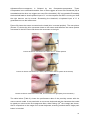
With the new built alternative input device, called proximity sensor, another possibility to use
a PC for people with physical limitations was developed. Using a reflective object sensor
(consisting of an infrared diode and a phototransistor) to measure the distance between the
user’s chin and the sensor, provides easier computer access also for people who suffer from
a Tetraplegia and therefore are only able to move their head. Furthermore, after the
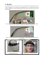
calibration process that includes the correct placement of the sensor on the mounting wire at
the chin, no strength is needed to operate the sensor. It is also important to mention that also
small and very exact mouse pointer movements are possible as the chin can be moved very
precisely and the corresponding curve of the chin movement can be adjusted individually.
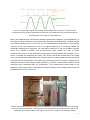
Due to the pulsing of the infrared diode a minimization of the influence that is caused by the
ambient light’s amount of infrared light was achieved. However, the ambient light’s influence
is not completely blinded out. This could be caused by the reason, that due to the amount of
infrared light that is present in the ambient light, the amplitude of the square-wave signal and
the therefore the amplitude of the sinus-shaped signal get higher. To counteract this
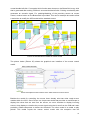
circumstance, the ACS-models for mouse control and pinball include the AdjustmentCurvecomponent. This component makes it possible to define the zero point/neutral position of the
chin every time the proximity sensor is started or after a change of the lighting conditions.
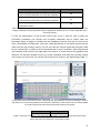
With the mouse model, the user is able to control the mouse pointer movement in horizontal
as well as vertical directions. Furthermore one can decide what kind of click should be
carried out next. There are three possibilities: double click (left), right click and drag click.
After the chosen click was carried out, the next click will be a double click as it is set as
standard click.
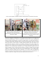
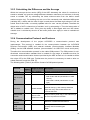
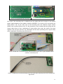
Before the proximity sensor could be used on the designed PCB, the printed circuit board
was tested. This brought up some problems that were related to the SMT (surface-mount
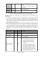
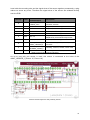
technology) 22nF capacitors (Table 5 and Picture 15, C3 and C4) of the parallel resonant
circuit. Although the chosen SMT capacitors were film capacitors and have the same
properties (according to their datasheet) like the normal sized through-hole capacitors, they
do not show the same behavior at the frequency of 9.174kHz. This could either be caused by
the capacitors tolerances or by a production fault. To solve the problem, the SMT capacitors
were replaced by the through-hole capacitors that were used on the pinboard. After this
exchange, the proximity sensor could be used as it was planned.
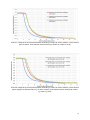
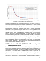
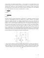
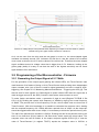
As shown in the results, after a little training with the proximity sensor, the mouse pointer
movements can be carried out rather fast. This is also good for applications that include an
on-screen keyboard (e.g. Oska). The on-screen keyboard can be used directly instead of
using it with scanning methods [1]. Although there is not a big difference in the number of
characters that can be written when using the scanning methods (combined with a push
button) and when using the proximity sensor, the latter has the huge advantage that not only
the keyboard can be used, but all normal mouse functions can be carried out as well.
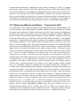
Comparing the mouse functions of the proximity sensor with those provided by a one-switchmouse, one can see that the time that is needed to open a homepage and to download a file
can be reduced by about 50%.
37