1
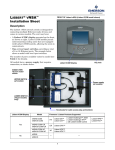
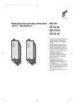
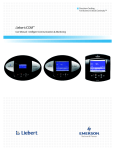
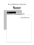
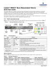
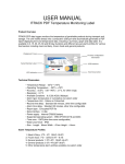
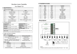
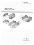
LIEBERT VNSA
Installation Sheet
FRONT OF vNSA
iCOM model shown
Description
The Liebert vNSA network switch is designed
for connecting multiple Ethernet-ready devices
and comes in various models:
Model
vNSA8-iCOM
vNSA16-iCOM
iCOM
Display
Yes
vNSA8
vNSA16
No
Number of
available ports
7
13
8
14
• The unit may have an iCOM™ display
mounted on the front, as shown at right.
iCOM models permit interconnecting
cooling units that are equipped with iCOM
controls, allowing the units to communicate
and function as a team and facilitating
lead/lag operation.
iCOM display
Key lock
• The number of 8-port switches may be
one or two, for a total of 8 or 16 Ethernet ports. The example below shows two 8-port switches.
• All models have a power supply that requires connection, as shown below.
INSIDE VIEW
16-port model shown
UPPER SWITCH
(all models)
LOWER SWITCH
(16-port models only)
Knockouts for cable access
(top and bottom)
1
Power supply
(all models)
Packing Contents
The vNSA comes standard with these components:
• iCOM display on front of enclosure (iCOM models only)
• One 8-port switch inside enclosure (8-port models)
or
Two 8-port switches inside enclosure (16-port models)
• Universal power supply and hardwire adapter
• Keys (2) to panel door lock
• User manual for vNSA
• User manual for industrial rail switch
• User manual for iCOM (iCOM models only)
Factory Connections
The vNSA has factory-wired connections to simplify installation, depending on the model (see
Figure 1):
Models with iCOM display
• The upper switch is factory-connected to the iCOM display.
16-port models
• The upper switch is factory-connected to the lower switch.
All models
• Proper power connections are factory-wired between the 3-pin terminal blocks on each switch.
Figure 1
Factory-wired connections
UPPER SWITCH
(all models)
Cable connecting
upper switch to lower switch
(16-port models only)
Cable connecting
upper switch to iCOM display
(iCOM models only)
LOWER SWITCH
(16-port models only)
2
Switches
Each switch has eight 10/100 Mbps twisted pair RJ45 ports, allowing connection of Ethernet-ready
devices to available ports.
The switch supports Ethernet 10 Mbps and Fast Ethernet 100 Mbps using twisted-pair RJ45 ports,
allowing connection of Ethernet-ready devices. The devices support switched Ethernet networks in
accordance with IEEE standard 802.3.
Three automatic features—autonegotiation, autopolarity and autocrossing—allow the use of standard
network cables (CAT5 or better) for connection to each port, rather than a special crossover cable. The
switch detects and makes adjustments for the network’s speed and transmission mode, polarity and
transmit-and-receive pins. Refer to the Industrial Rail Switch user manual for more details.
Connecting Devices
Use CAT5 or better cables with RJ45 connectors to connect devices to available ports.
The number of ports available for Ethernet-ready devices varies by model, as shown in Table 1.
Models with the iCOM display use one port for connection to the iCOM display; models with two
switches use two ports to interconnect the switches.
Table 1
Number of available ports by model
iCOM
Display
Model
vNSA8-iCOM
vNSA16-iCOM
vNSA8
Total
# ports
Yes
No
vNSA16
# ports used to
connect to iCOM
# ports used to
connect switches
Number of
available ports
8
1
—
7
16
1
2
13
8
—
—
8
16
—
2
14
The maximum number of cooling units that may be connected depends on the vNSA model and
the size of the iCOM display in those units, as shown in Table 2.
Table 2
Number of cooling units that may be connected
With Small
iCOM Display
With Large
iCOM Display
vNSA8-iCOM
7 units
3 units
vNSA16-iCOM
13 units
6 units
vNSA8
8 units
4 units
vNSA16
14 units
7 units
Model
Refer to the iCOM user manual for additional details on connecting Liebert cooling products.
3
Connect Power to the vNSA
The vNSA requires AC power (100-240VAC single phase) for proper operation. A universal power
supply (12V, 1.5A) is installed inside the enclosure, with a hard-wired connection for 120V or 230V
operation.
!
!
WARNING
Check that power is removed from wires prior to installation.
CAUTION
The vNSA is designed for use on properly grounded (earthed) 100-240VAC single-phase
power, 50Hz or 60Hz. The ground wire for the power lead must be wired to the earth ground
terminal (stud located next to the universal power supply).
This equipment is intended to be installed by a qualified and certified electrician who must
review and approve customer supplied wiring and circuit breakers, verify correct input and
grounded (earthed) connections to ensure compliance with technical standards and national
and local electrical codes.
NOTE
The connector must be unplugged prior to installation.
A field-supplied power cord may be used in place of the hardwire adapter provided.
Power Supply Wiring Instructions
1. Loosen and remove the screw from the adapter cover.
Loosen
cover
screw
D
2. Remove the cover.
N
Fl
Remove
cover
N
E L
3. Loosen the two screws that secure the wire clamp. Remove the screws and the wire clamp.
N
Screws
E L
Wire
clamp
4
4. Connect the incoming electrical service ground wire to the earth ground terminal inside the enclosure,
shown below.
Earth ground
terminal
5. Feed wires—including a ground wire from the earth ground terminal in Step 4—through the rubber
strain relief into the adapter. Note: 16 AWG stranded maximum wire size.
N
Rubber
strain
relief
E L
6. Strip the insulation on each wire to expose 5/8" (16mm).
N
E L
Strip insulation
to expose 5/8" (16mm)
7. Loop each wire around the appropriate terminating screw and tighten. Each screw is labeled:
• N = Neutral for 120V; Line for 220V applications
• E = Earth ground
• L = Line
Neutral for 120V; Line for 220V applications
(white)
N
E L
Earth grounding conductor
(green)
Line
(black)
8. Replace the wire clamp and the two screws removed in Step 3 to secure wires.
9. Close the adapter cover and tighten the screw from Step 1.
5
Enclosure
The vNSA enclosure features a key lock for added
security. The enclosure is made of metal to
accommodate secure conduit fittings and protect
components against environmental debris.
14.25"
(361.95mm)
The enclosure is designed for easy wire routing and
terminations. Access slots for network cables and
power wiring are located on both the top and bottom
of the enclosure.
12"
(304.8mm)
The enclosure is 3.3" (84mm) deep, allowing for
recess mounting in a wall. The enclosure may also be
surface-mounted.
The enclosure houses the power supply and one or
two 8-port rail switches. Some models have an iCOM
display mounted on the front of the enclosure.
Enclosure Mounting Considerations
The vNSA must be installed indoors. The enclosure
must be secured to a wall, either mounted on the
surface of a wall or recessed with the front flush
against a wall. The method of mounting depends on
the application, the location of equipment to be
monitored and the type of wall the enclosure will be
mounted on.
• The vNSA should be mounted where it can be
easily accessed.
• The site must have electrical service and must
permit routing of network cables to the unit’s
RJ45 ports.
• The wall material must be capable of supporting
the weight of the vNSA: see Specifications on
page 8.
6
FRONT VIEW
(all models)
3.3"
(84mm)
TOP/BOTTOM VIEW
(vNSA8 & vNSA16 models)
7/8"
(22mm)
4.175"
(106mm)
TOP/BOTTOM VIEW
(iCOM models)
Surface Mounting
NOTE
Removing the conduit knockouts before mounting the vNSA on the wall will ease installation
and prevent strain on the mounting hardware and wall.
After determining where to place the enclosure, check to ensure that you have all the hardware
required to install the panel on the surface of a wall. Obtain the needed tools and material.
Required Tools
•
•
•
•
Electric drill (if surface is too hard to drive screws without pilot holes)
Screwdriver
Marker to denote layout of holes
Four screws, each #10
Mounting the Panel
!
CAUTION
Check building plans and other relevant documents to determine whether mounting the
vNSA at the selected location might cause cutting or otherwise damaging electrical or
communication wiring or pipes.
1. Mark the wall for mounting holes, using the back of the unit as a template (see Figure 2).
Figure 2
Mounting dimensions
12-1/2"
(318mm)
0.88"
(22mm)
0.213"
(5mm)
A
10"
(254mm)
0.694"
(18mm)
0.375"
(10mm)
1" (25mm)
Back Plate
(inside view)
Detail “A”
Mounting Slot
0.213" (5mm)
(two places)
2. Drill holes, if required, to install the four #10 screws that will secure the vNSA to the wall. Clean
up the debris.
3. If the wall material is not strong enough to hold the screws securely, use wall anchors.
4. Install the top two screws—the screw heads must be small enough to slip through the larger,
bottom portion of the pear-shaped mounting slot in the vNSA (see Figure 2). The screws must
also be large enough to extend over the edges of the top of the mounting slot.
5. Hang the vNSA on the screws, letting the panel slip down until the screws are in the smaller,
upper portion of the slot.
6. Tighten the screws until they are snug.
7. Insert the remaining two screws in the bottom holes on the back of the panel and tighten.
7
Specifications
MODEL
vNSA8-iCOM / vNSA16-iCOM
Power
vNSA8 / vNSA16
100-240VAC, single-phase, 47-63 Hz, 0.4A
Dimensions, W x D x H - in. (mm)
14.25 x 3.3 x 12 (362 x 84 x 305)
Weight - lb. (kg)
11 (5)
Enclosure Type
10 (4.5)
NEMA 1, painted steel IP20 - indoor use
Mounting Surface
Building wall or structural member
Communication
Ethernet 10/100 Mbps RJ45 ports, autonegotiation, autopolarity and autocrossing
Ambient Operating Environment
32°F to 140°F (0°C to 60°C); 0 to 95% relative humidity, non-condensing.
Wiring Specifications
Connection
Supported Wire Types
Maximum Wire Length
Rating
Ethernet 10/100 Mbps
CAT 5 RJ45 Ethernet cable
328 ft. (100m)
N/A
Universal power supply
16 AWG Stranded
Contact local electrician
300V
Ordering Information
Quantity
Part #
Description
vNSA8-iCOM
vNSA with iCOM display and 8 ports
vNSA16-iCOM
vNSA with iCOM display and 16 ports
vNSA8
vNSA with 8 ports
vNSA16
vNSA with 16 ports
Liebert Corporation
1050 Dearborn Drive
P.O. Box 29186
Columbus, OH 43229
Telephone: 1-800-877-9222
Facsimile: 1-614-841-6022
www.liebert.com
© 2006 Liebert Corporation
All rights reserved throughout the world. Specifications subject
to change without notice.
® Liebert and the Liebert logo are registered trademarks of
Liebert Corporation. All names referred to are trademarks or
registered trademarks of their respective owners.
SL-18840_REV0_09-06
8