1
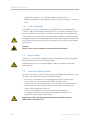
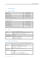
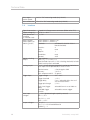
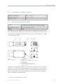
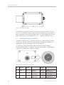
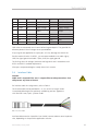
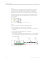
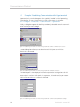
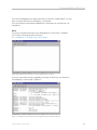
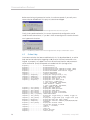
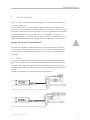
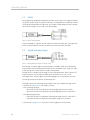
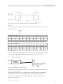
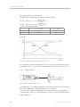
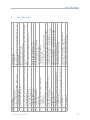
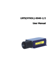
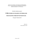
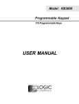
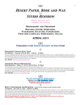
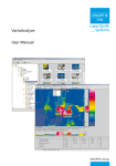
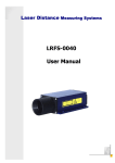
LDM41/42 Manual Revision 003, January 2007 Dear User You are advised to carefully read this User Manual before powering on the LDM41/42 laser distance measuring module for the first time. This is necessary to ensure that you will be able to utilize all the capabilities and features which your new acquisition provides. This technology is subject to continuously ongoing development. Editorial deadline: January 2007 Document number: 012840-007-98-02-0107-en JENOPTIK Laser, Optik, Systeme GmbH Sensor Systems business unit 07739 Jena Germany Phone: 0 36 41 - 65 33 14 Fax: 0 36 41 - 65 36 57 E-Mail: [email protected] Revision state Date Revision January 2007 003 Explanation Compiled CE Note No part of this User Manual may be reproduced in any way (by photographing, photocopying, microfilm or any other technique) without prior written approval by JENOPTIK Laser, Optik, Systeme GmbH, nor may it be processed, duplicated or disseminated with the help of electronic systems. Proper care has been used in compiling this document. No liability will be accepted in the event of damage resulting from failure to comply with the information contained herein. Revision 003, January 2007 Dear User For highlighting purposes, the following pictograms, signs of reference and warning symbols are used throughout this Manual: Warning and reference symbols • Enumeration + Advice/Important/Important Note g Reference (to a passage of text or a Figure) Warning symbols Warning: Indicates potential health risks that may occur if symbols of this type are disregarded. Caution: Warns of potential product damage. Laser: Warns of potential exposure to emerging visible or invisible laser radiation. Information: Provides a reference to important data or details. Revision 003, January 2007 Content 1 2 2.1 2.2 2.3 2.4 2.5 2.6 3 3.1 3.2 3.3 3.4 3.5 3.6 3.7 3.8 4 4.1 4.2 4.3 4.3.1 4.3.2 4.3.3 4.3.4 4.3.5 4.3.6 4.3.7 4.3.8 4.3.9 4.3.10 4.3.11 4.3.12 4.3.13 4.3.14 4.3.15 4.3.16 4.3.17 4.3.18 4.3.19 4.3.20 4.3.21 4.3.22 4.3.23 General Safety Instructions Basic Notes Intent & Conforming Use Nonconforming Use Laser Classification Electrical Supply Important Operating Advice Technical Data Scope of delivery Laser Measuring Performance Interface Environment & Ambient Conditions Mecanical Mounting Conditions Electrical Mounting Conditions Interface Cable Communications Protocol Example: Establishing Communication with Hyperterminal Online Help Commands and their functions DT..........distancetracking DS.......distancetracking 7 m DW.......distancetracking with cooperative target (10Hz) DX.........distancetracking with cooperative target (50Hz) DF..........distance measurement with external trigger DM..........distance measurement TP..........internal temperature [°C] SAx..........display/set average value [1..20] SDd..........display/set display format [d/h] STx..........display/set measure time [0..25] SFx .x..........display/set scale factor SEx..........display/set error mode [0/1/2] ACx.x..........display/set ALARM center AHx.x..........display/set ALARM hysterese AWx.x..........display/set ALARM width RB..........display/set distance of Iout=4mA RE..........display/set distance of Iout=20mA RMx y.y z......remove measurement TDx y....display/set trigger delay [0..9999ms] trigger level [0/1] TMx y......display/set trigger mode [0/1] trigger level [0/1] BRx..........display/set baud rate [2400..38400] AS...display/set autostart command [DT/DW/DX/DF/DM/TP/LO] OFx.x..........display/set distance offset Revision 003, January 2007 7 9 9 9 9 10 10 10 11 11 11 11 12 13 13 14 15 17 18 20 21 21 21 22 22 22 22 22 23 23 23 24 24 25 25 25 25 26 26 27 27 28 29 29 Content 4.2.24 4.2.25 4.2.26 4.2.27 4.2.28 5 5.1 5.2 5.3 5.4 5.5 6 7 8 SO..........set current distance to offset (offset = - distance) 29 LO..........laser on 29 LF..........laser off 29 PA..........display settings 29 PR..........reset settings30 Operating Modes31 RS23231 RS42232 Digital Switching Output32 Analog Output33 Trigger Input34 Error Messages35 Service & Maintenance37 EC - Declaration of Conformity39 Revision 003, January 2007 General 1 General The LDM41/42 is a laser range finder to measure distances from 0.1 m to more than 100 m with pinpoint accuracy. A given target can be clearly identified with the help of a red laser sighting point. In terms of operating reach, the LDM41/42 performs depending on the reflectance, morphology and qualities of the target to be measured. The range finder works based on comparative phase measurement. It emits modulated high-frequency light which is diffusely reflected back from the target with a certain shift in phase to be compared with a reference signal. From the amount of phase shift, a required distance can then be determined with millimeter accuracy. A distance measuring cycle can be triggered in four different ways: - By sending a command from the PC or another equivalent control unit - By making appropriate prior parameter settings for the autostart command and applying supply voltage - By external triggering (in remote-trigger mode) - Using the autostart trigger function. For a more detailed description of these four trigger options, you should consult section 5. Operating Modes of this User Manual. Special performance features are: - Provides high accuracy and great reach under extreme outdoor temperatures. - Works in a wide range of operating voltages from 10 V= to 30 V= from an onboard vehicle supply point, an industrial direct voltage supply net or a DC power pack. - Features consistently low power consumption of <1.5 W (without IAlarm). - Up to 30 m reach for distance measurement, with potential for more than 100 m reach if additional reflectors are mounted onto the target (depending on reflectance and environmental conditions). - Visible laser beam for easier sighting. - RS232 interface port for input of measuring functions and commands from, and output of measured values to, a PC or a laptop. - Switching output and analog output are separately programmed. - Switching output with adjustable limit to indicate positive and negative excession of preselectable distance range window by sighting distance. - Measured values can be displayed in meters, decimeters, centimeters, feet, inches due to. - Option for remote triggering of a measurement from an external trigger device. The LDM41/42 measuring module is shipped in a rugged cardboard box with adequate padding for safe transportation. Revision 003, January 2007 General Revision 003, January 2007 Safety Instructions 2 Safety Instructions 2.1 Basic Notes These safety and operating instructions should be carefully read and followed during practical work with the LDM41/42. There is danger of laser radiation or electrical shock. For necessary repair work, the LDM41/42 may not be opened by anyone other than Manufacturer personnel. Unauthorized intervention into the inner product space will void any warranty claims. Compliance with all specified operating conditions is necessary. Failure to observe advisory notes or information contained in this Manual or nonconforming product usage may cause physical injury to the user or material damage to the LDM41/42. Cable connectors must not be plugged or unplugged, as long as voltage is supplied. Remember to turn voltage supply off before you begin working on cable connections. 2.2 Intended & Conforming Use •Measurement of distances • Special measuring functions • Compliance with prescribed temperatures for operation and storage • Operation at correct voltage level • Application of specified signal levels to the appropriate data lines. 2.3 Nonconforming Use • Do not operate the LDM41/42 in any other way than described under “Intended & Conforming Use“ above and only in a proper working condition. • Safety devices must not be defeated or otherwise rendered ineffective. • Information and warning signs must not be removed. • Repair work on the LDM41/42 must not be carried out by anyone other than JENOPTIK personnel. • Refrain from using the LDM41/42 in an explosive environment. • Measurement with the LDM41/42 pointed at the sun or other strong lightsources may produce faulty results. • Measurement of targets with poor surface reflectance in a strongly reflecting environment may also result in faulty measurement values. • Measurement of strongly reflecting surfaces may deliver faulty results. • Measurement performed through transparent optical media, for example, glass, Revision 003, January 2007 Safety Instructions optical filters, plexiglass, etc. may equally produce incorrect results. • Rapidly changing measuring conditions are likely to falsify the result of ment. 2.4 measure- Laser Classification The LDM41/42 is a class 2 laser product as stipulated in IEC825-1/DIN EN 608251:2001-11 and a class II product under FDA21 CFR. In the event of accidental, shorttime laser exposure, the human eye is sufficiently protected by its own optico-facial winking reflex. This natural reflex may be impaired by medication, alcohol and drugs. Although the product can be operated without taking special safety precautions, one should refrain from directly looking into the laser beam. Do not direct the laser beam onto persons. Caution: There is class 2 laser radiation. Do not look into the beam! 2.5 Electric Supply Use only 10 V to 30 V direct voltage for LDM41/42 operation. Use only the specially designated connector terminal for voltage supply. Specified signal levels must not be exceeded, in order to guarantee correct data communication. 2.6 Important Operating Advice To make full use of the system’s inherent performance capabilities and achieve a long service life, you should always follow these operating rules: • • • • • • • Do not turn the module on if there is fogging or soiling on its optical parts! Do not touch any of the module’s optical parts with bare hands! Proceed with care when removing dust or contamination from optical surfaces! Prevent exposure to shock impacts during transportation of the LDM41/42! Prevent overheating of the LDM41/42! Prevent major temperature variances during LDM41/42 operation. In accordance with IP65 internal protection standards, the LDM41/42 is designed to be splashproof and dustproof. Read these safety and operating instructions with due care and follow them in practical use. 10 Revision 003, January 2007 Technical Data 3 Technical Data 3.1 Scope of delivery Description LDM41.1 (RS232) LDM41.2 (RS422) LDM42.1 (RS232) LDM42.2 (RS422) CD with Customer documentation Optional accesssories Description Power chord, 2 m Power chord, 5 m Power chord, 10 m 12-pol jack (female) Set of Customer documentation (hardcopy) 3.2 Part number 012840-136-24 012840-137-24 012840-138-24 94477 Laser Laser: Laser class: Output power: Laser divergence: Beam diameter: 3.3 Part number 012840-411-22 012840-412-22 012840-421-22 012840-422-22 650 nm laser diode; red light 650 nm, visible, laser class 2, conforming to standard IEC825-1/EN60825, class II (FDA21 CFR) < 1mW 0.6 mrad < 11 mm at 10 m distance < 35 mm at 50 m distance < 65 mm at 100 m distance Measuring Performance Measuring range1: 0.1 m to 30 m for natural, diffusely reflecting surfaces (for DT, DF or DM and ST =0), and up to 150 m with a target board Measuring ± 2 mm for white surfaces, (+15 °C ... +30 °C) accuracy: ± 3 mm for natural surfaces, (+15 °C ... +30 °C) ± 4 mm at 0.1 ... 0.5 m range in DS mode, (+15 °C ... +30 °C) ± 5 mm (-10 °C ... +50 °C) Measured value Depends on scale factor (1 mm with SF = 1) resolution: Time to measure: typ. 160 ms ... 6s in standard mode measuring any type of surface 100 ms in “DW“ measuring mode 20 ms in “DX“ measuring mode (only LDM42) 1 conditional on target reflectance, ambient light influences and atmospheric conditions Revision 003, January 2007 11 Technical Data Max. target 4 m/s in “DX“ measuring mode (only LDM42) motion speed: Max. acceleration: 2.5 m/s² in “DX“ measuring mode (only LDM42) 3.4 Interface Type of connection: Supply voltage (UV): Max. power consumption (in no-load state): Data interface: (Please specify on ordering sheet!) Digital switching output: Analog output: Trigger input: Max. input voltages: Output voltages: 12 12-pole M18 flange-mount connector (Binder series 723) DC 10 V ... 30 V < 1,5 W RS232 (LDM41.1, LDM42.1) or RS422 (LDM41.2, LDM42.2), Baud rate: 9.6 kBaud (2.4/4.8/19.2/ 38.4 kBaud selectable) Data bits: 8 Parity: none Stop bit: 1 Handshake: none Protocol: ASCII Open collector HIGH = UV – 2 V, LOW < 2 V, rated for loads up to 0.5 A, with switching threshold, latitude (width) and hysteresis selectable 4 mA ... 20 mA, distance range limits can be set, behavior on error report can be preselected, 3 mA or 21 mA Load resistance: ≤ 500 Ω against GND Accuracy: Max. temperature drift: Trigger voltage Trigger threshold Trigger delay ± 0.15 % 50 ppm/K 3 V ... 24 V + 1.5 V, 5 ms + selectable delay time until start of measurement ≥ 1 ms selectable from 0 ms to 9999 ms Trigger pulse length Delay time (trigger delay) Extended trigger selectable autostart trigger function UV = 30 V (protected against polarity reversal) RxD = ± 25 V RX+, RX- = ± 14 V TRIG = + 25 V TxD ≥ 5 V TX ± 2 V, 2 x 50 W load differential ALARM UV – 2 Revision 003, January 2007 Technical Data 3.5 Environment & Ambient Conditions Operating temperature: - 10 °C ... + 50 °C Storage temperature: - 20 °C ... + 70 °C Protection type: IP65 3.6 Mechanical Mounting Conditions Casing: Extruded aluminum profile with powder-coat paint finish, front-side & rear-side cover and tube anodized 182 mm x 96 mm x 50 mm 850 g Dimensions (L x W x H): Weight: The casing consists of a rugged, corrosion-resistant extruded aluminum profile with front-side and rear-side covers also in corrosion-resistant design. Four mounting holes are provided in the baseplate for mechanical attachment of the LDM41/42 (g Figure 1: Dimensional drawing). Figure 1: Dimensional drawing 1 2 3 4 5 6 7 Equalizer tube at front cover Casing Protective cap for flange-mount connector Receiver optics Sender optics Mechanical mounting holes (four) 12-pole M18 flange-mount connector (Binder series 723 To protect the range finder’s optical surfaces from dust, physical contact, mechanical impacts, etc., the casing has a special equalizer tube attached to it. This tube can be extended or removed2 as necessary to meet the customer’s operating needs . Please note that measurement cannot be guaranteed to function correctly if the equalizer tube is removed by unqualified action! 2 consult your local distributor on this issue Revision 003, January 2007 13 Technical Data Figure 2: Offset against zero-edge The LDM41/42’s zero-point is located 7 mm behind the outer surface of the front cover or 137 mm before the back cover outside face respectively. This zero-point has been introduced for constructional design reasons. It can be compensated with the help of parameter “OF“ (see section 4.3.19 „OF.......display/set distance offset“). 3.7 Electrical Mounting Conditions Located on the back cover is a connector terminal. A 12-pole round-type (flangemount) series 723 connector from Binder has been selected for this purpose. It is sealed against the casing to comply with IP 65 requirements. This connector type guarantees optimized screening and a high IP degree. The required counterpart is a cable jack (series 423 from Binder) with grading ring. A cable set with open ends is optionally available. Figure 3: View of LDM41/42 pole assignments 14 Pin Interfacecable LDM41 LDM42 A Green TxD RS232send data RX+ RS422receive data + B Yellow RxD RS232receive data RX- RS422receive data - C Brown TRIG External trigger input TRIG External trigger input Revision 003, January 2007 Technical Data D Red IOUT E Black F Analog output IOUT Analog output n.c. TX- RS422-send data - Violet n.c. TX+ RS422-send data + G Orange UV Supply voltage UV Supply voltage H White ALARM Digital switching ALARM output Digital switching output J Gray GND GND GND K - n.c. L Blue GND M - n.c. GND n.c. GND GND GND n.c. Table 2: Pinout assignments GND wires are connected to an internal collective ground point. They provide the reference potential for all voltage values quoted below. If input signals are applied to an output port, this may damage the LDM41/42! For data communication via RS232, you are recommended to use cable 4 (gray, GND) for signal ground and cable 7 (blue, GND) for supply ground! The limiting values of voltages, load rates and logic levels are in accordance with RS232 and RS422 standard requirements. All outputs are protected against steady short-circuit currents. 3.8 Interface Cable Caution: Cable end is exposed! The user is responsible to take precautions that will prevent any kind of shorts! For interface cable wire assignments, refer to Table 2. The interface cable can be provided in 2 m, 5 m and 10 m length version. Customized cable lengths are optionally available by previous agreement with JENOPTIK Laser, Optik, Systeme GmbH. Bild 4: Interface-Kabel Interface cable extension is possible. One should, however, observe some important rules, depending on the particular application scenario: Revision 003, January 2007 15 Technical Data LDM41 RxD and TxD data lines should be kept as short as possible in all cases, because they tend to have an interference emitting and interference receiving effect, notably, when in open state. Especially in environments with strong spurious radiation there may be faults that may in some cases require a reset (turning the LDM41 off and on again). In cases where no RS232 interface communication is required after parameterization, you should provide for a termination wiring as shown in Figure 5. Figure 5: Recommended termination wiring for work with open RS232 LDM42 Extension and termination according to standard requirements. For correct screening, three essential rules must be followed: 1. Use screened cable, e.g. “10XAWG224CULSW“, remember to extend also the cable screen! 2. Connect screen to reference potential of UV on cable end. 3. For integration with vehicles: Where attachment point and reference potential (GND or “-“) have equal potentials, it may be necessary to electrically isolate the LDM41/42 casing, in order to prevent ground loops. Figure 6: Correct screening of LDM41/42 16 Revision 003, January 2007 Communications Protocol 4 Communications Protocol The easiest way to trigger and parameterize the LDM41/42 is by using a PC with RS232 communication port (see 5.1 RS232) and a terminal program (see 4.1 Example: Establishing Communication with Hyperterminal). The communications protocol is available in ASCII format. Before an operating session begins, desired parameter settings can be made in a smart selection procedure until the measuring module is optimally adapted to the particular measuring site conditions and the measuring job. All valid settings will be preserved on turning the LDM41/42 off! They can only be replaced with new value entries or changed back to their standard values by running an initialization routine. The following is a short overview of the communications protocol Command DT DS DW DX DF DM TP SA SD ST SF SE AC AH AW RB RE RM TD TD BR AS OF SO LO LF PA PR Description Starts distance tracking Starts distance tracking 7 m Starts distance tracking on white target at 10 Hz Starts distance tracking on white target at 50 Hz (only LDM42) Starts remote-triggered single distance measurement (single shot) Starts single distance measurement (single shot) Queries inner temperature Queries / sets floating average value (1...20) Queries / sets output format (dec/hex) Queries / sets time to measure (0...25) Queries / sets scale factor Queries / sets error mode (0, 1, 2) Queries / sets alarm center Queries / sets alarm hysteresis Queries / sets alarm width Queries / sets beginning of range (4 mA) Queries / sets end of range (20 mA) Queries / sets removal of measured value Queries / sets trigger delay Queries / sets trigger mode Queries / sets baud rate Queries / sets autostart Queries / sets offset Sets current distance as offset Turns laser on Turns laser off Displays all parameter values Resets all parameters to standard values Table 3: Short overview of communications protocol Revision 003, January 2007 17 Communications Protocol 4.1 Example: Establishing Communication with Hyperterminal Hyperterminal is a terminal program that is typically included in Win32 operating system delivery. To start Hyperterminal, use the starting menu in this order: Start g Programs g Accessories g Communication g Hyperterminal Initially, a dialog box appears for defining a randomly selectable name of a communication session you want to begin. Figure 7: Establishing communication with the hyperterminal: name of communication session A second dialog box allows you to select the serial COM port to which the LDM41/42 is connected. Figure 8: Establishing communication with the hyperterminal: COM port selection A third dialog box is then displayed with various parameter setting options for this communication session. At this point in the process, the baud rate (bits per second) and the flow control must be correctly initialized. Figure 9: Establishing communication with the hyperterminal: communication parameter settings 18 Revision 003, January 2007 Communications Protocol Once the third dialog box has been confirmed, the terminal window opens. Its status bar in the lower left corner should display “Connected“. With the LDM41/42 powered and operational, commands can now be input, for example ID. Note: A currently entered command will only be displayed if “Local echo“ is enabled. This function can be accessed via File menu File g Properties g “Settings“ tag g ASCII Setup. Figure 10: Establishing communication with the hyperterminal: ID input Once this command has been triggered by pressing the Enter key, the LDM41/42 should display its online help in response. Figure 11: Establishing communication with the hyperterminal: LDM41/42 response Revision 003, January 2007 19 Communications Protocol Before terminating a hyperterminal session, the software queries if you really want communication abandoned. This query must be acknowledged. Figure 12: Establishing communication with the hyperterminal: disconnect query box Finally (unless performed earlier), the current hyperterminal configuration can be saved for more convenience, i.e. you don’t have to reconfigure the interface for each new hyperterminal session. Figure 13: Establishing communication with the hyperterminal: saving a communication session 4.2 Online Help Once communication has been established with a PC (as described above), an online help tool can be called up by triggering an ID [Enter] or id [Enter] command at the keypad. Its purpose is to support work with distance measurement and parameterization commands. [Enter] corresponds to hexadecimal 0Dh (carriage return) DT[Enter].....................distancetracking DS[Enter].....................distancetracking 7m DW[Enter].....................distancetracking with cooperetive target (10Hz) DX[Enter].....................distancetracking with cooperetive target (50Hz) DF[Enter].....................distance measurement with external trigger DM[Enter].....................distance measurement TP[Enter].....................internal temperature [°C] SA[Enter] / SAx[Enter]........display/set average value [1..20] SD[Enter] / SDd[Enter]........display/set display format [d/h] ST[Enter] / STx[Enter]........display/set measure time [0..25] SF[Enter] / SFx.x[Enter]......display/set scale factor SE[Enter] / SEx[Enter]........display/set error mode [0/1/2] 0..Iout=const., ALARM=const. 1..Iout: 3mA @RE>RB, 21mA @RE<RB, ALARM: OFF@AH>0, ON@AH<0 2..Iout: 21mA @RE>RB, 3mA @RE<RB, ALARM: ON@AH>0, OFF@AH<0 AC[Enter] / ACx.x[Enter]......display/set ALARM center AH[Enter] / AHx.x[Enter]......display/set ALARM hysterese AW[Enter] / AWx.x[Enter]......display/set ALARM width RB[Enter] / RBx.x[Enter]......display/set distance of Iout=4mA RE[Enter] / REx.x[Enter]......display/set distance of Iout=20mA RM[Enter] / RMx y.y z[Enter]..remove measurement TD[Enter] / TDx y[Enter]......display/set trigger delay [0..9999ms] trigger level [0/1] TM[Enter] / TMx y[Enter]......display/set trigger mode [0/1] trigger level [0/1] BR[Enter] / BRx[Enter]........display/set baud rate [2400..38400] AS[Enter] / ASd[Enter]........display/set autostart command [DT/DS/DW/DX/DF/DM/ TP/LO/ID] OF[Enter] / OFx.x[Enter]......display/set distance offset SO[Enter].....................set current distance to offset (offset = - distance) LO[Enter].....................laser on LF[Enter].....................laser off PA[Enter].....................display settings PR[Enter].....................reset settings 20 Revision 003, January 2007 Communications Protocol 4.3 Commands and their functions Command entries are not case-sensitive. This means that small and capital lettering can be used for commands. Any command which is to be sent to the LDM must be terminated by a hexadecimal 0Dh (carriage return) character. Where decimal digits are to be entered, they must be separated by period (2Eh). For command paramater entries, one must distinguish between parameter settings and parameter queries. Querying is achieved with a command in simple format. AC[Enter] e.g. (for alarm center parameters): For parameter setting, a new value must be added after the command with no AC20.8[Enter] delimitation sign in between, for example: In the given example, the alarm center will be set to 20.8. 4.3.1 DT......distancetracking Input parameter SA, SD, SE, SF, ST, OF Output RS232/RS422, digital switching output, analog output DT mode can be chosen for distance measurement of different kinds of surfaces (varying reflectance). Working in this mode, the LDM41/42 uses internal algorithms to continuously evaluate the quality of laser radiation that is received back. This may cause longer measuring times in the case of varying reflectance or sudden jumps in distance. The minimum time to measure is 160 ms, the maximum time is 6 s. If the measuring signal fails to reach a specified quality within six seconds, an error message is output. The time to measure may also be limited by setting the ST parameter to a desired value. 4.3.2 DS ...... 7m distance tracking Input parameter SA, SD, SE, SF, ST, OF Output RS232/RS422, digital switching output, analog output Operation in DS mode makes sense where different types of surfaces have to be measured at close range up to 7 m. Compared to DT measuring mode, it allows a higher measurement rate. Within the range from 0.1 m to 0.5 m, measuring accuracy is restricted. Measuring time (time to measure) can be limited via ST parameter settings. Revision 003, January 2007 21 Communications Protocol 4.3.3 DW......distance tracking with cooperative target (10Hz) Input parameter SA, SD, SE, SF, OF Output RS232/RS422, digital switching output, analog output DW mode performs at a steady measuring rate of 10 Hz. As a necessary precondition for measured values to be stable, a white target board must be placed at the selected object. There must be no sudden jumps in distance greater than 16 cm within the measuring field! 4.3.4 DX......distance tracking with cooperative target (50Hz) Input parameter SA, SD, SE, SF, OF Output RS232/RS422, digital switching output, analog output DX mode performs at a steady measuring rate of 50 Hz (only LDM42). As a necessary precondition for measured values to be stable, a white target board must be placed at the selected object. This measurement mode is intended in the first place for objects performing homogeneous motion up to 4m/s. For higher rates of measurement, preceding measured values will be included in the process to calculate a currently measured value. There must be no sudden jumps in distance greater than 16 cm within the measuring field! 4.3.5 DF......distance measurement with external trigger Input parameter SD, SE, SF, ST, OF, TD Output RS232/RS422, digital switching output, analog output DF mode allows a measurement that is triggered by an external trigger pulse. Initially, after selecting this mode, the operator does not receive any response. As soon as the trigger pulse has been detected, the LDM41/42 will send data and switches to digital and/or analog output. Settings for trigger delay (delay) and trigger flank can be defined via parameter TD. (see 4.3.19 TD........display/set trigger delay [0..9999ms] trigger level [0/1]) 4.3.6 DM......distance measurement Input parameter SD, SE, SF, ST, OF Output RS232/RS422, digital switching output, analog output DM mode triggers a single measurement (single shot). 4.3.7 TP.......internal temperature [°C] TP queries the value of the inner LDM41/42 temperature. Note In tracking mode, the inner temperature may exceed the surrounding temperature level by as much as 10 K. 22 Revision 003, January 2007 Communications Protocol 4.3.8 SAx......display/set average value [1..20] Standard setting: 1 SA allows you to calculate a floating average value from 1 to 20 measured values. Calculation is based on this formula. Die Berechnung erfolgt über folgende Formel: x1 + x2 + x3 + ... + xn (20) Average value x = with n = SA n 4.3.9 SDd......display/set display format [d/h] Standard setting: d SD switches between decimal (d) and hexadecimal (h) output format of measured value data. SD affects all commands that output a distance value. A hexadecimal output value is calculated from a given measured distance value (in mm), multiplied by the scale factor SF. Negative distance values are output in two’s complement notation. Example: Distance = 4.996 m, SF1 dec: hex: Distance = 4.996 m, SF10 dec: hex: 4.996 001384 (= 4996 mm × SF1) 49.960 00C328 (= 49960 = 4996 mm × SF10) 4.3.10 STx......display/set measuring time [0..25] Standard setting: 0 Measuring time is directly conditional on the selected measuring mode. As a general rule, one may say: the poorer the surface reflectance of a selected target, the longer the LDM41/42 will take to determine a given distance with specified accuracy. For example, if error message E15 is output because of poor reflectance and insufficient time to measure, this latter setting must be increased. Available ST value range: 0 to 25 Basically, the greater the time setting is the more time will be available for measurement and the lower the resulting measuring rate. An exception therefrom is zero-value. In this case, the LDM41/42 automatically picks the smallest possible time value for measurement! The LDM41/42 comes factory-set with ST = 0. ST is effective in the DT, DS, DF and DM mode of operation. The measuring time setting option can also be used to modify the measuring rate, for example, in order to restrict the data volume or for synchronization purposes. Revision 003, January 2007 23 Communications Protocol Measuring time can only be set as an approximate value, because the underlying principle of measurement is subject to certain variances that cannot be accounted for: DT measuring mode g measuring time ≈ ST x 240ms (except ST = 0) DS measuring mode g measuring time ≈ ST x 150ms (except ST = 0) Example: The target distance is 25 m, but the target’s reflectance is not ideal. With a measuring time setting of ST 2, E15 will be output following measurement. The user must increase the time to measure in this case! Note: One should work in DW or DX measuring mode where stable measuring times are required. 4.3.11 SFx.x.....display/set scale factor Standard setting: 1 SF multiplies a calculated distance value with a user-selectable factor for changes in resolution or outputs in a different unit of measure. The scale factor may also be negative. Scale factor Resolution Output Unit of measure SF1 1 mm 12.345 m SF10 SF1.0936 0.1 mm 123.45 dm 0.01 yard 13.500 yard SF3.28084 0.01 feet 40.501 feet SF0.3937 1 inch 4.860 100 inch SF-1 1 mm -12.345 m Table 5: Examples of scale factor Note: Following a change in the scale factor, the settings for digital and/ or analog output and offset must be matched accordingly! 4.3.12 SEx......display/set error mode [0/1/2] Standard setting: 1 SE allows you to configure how the digital switching output (alarm) and/or the analog output is to behave on occurrence of an error message (E15, E16, E17, E18). Depending on the particular LDM41/42 application, different reactions to an error message are possible. Available selection options are 0, 1 and 2 with the following effects in the event of an error message: 24 Revision 003, January 2007 Communications Protocol SE Digital switching output (ALARM) Analog output (IOUT) 0 ALARM of latest valid measurement IOUT of latest valid measurement 1 AH: -AH: ALARM=LOW ALARM=HIGH RE>RB:IOUT=3 mA RE<RB:IOUT=21 mA 2 AH: -AH: ALARM=HIGH ALARM=LOW RE>RB:IOUT=21 mA RE<RB:IOUT=3 mA Table 6: Digital switching output and analog output for SE = 0, 1 and 2 4.3.13 ACx.x.....display/set ALARM center Standard setting: 1000 AC sets the beginning of the distance range, for which the switching output will be turned active. The length of this active range can be set using the AW parameter. AC must be selected in keeping with the currently set SF scale factor (refer to section 5.3 Digital switching output). 4.3.14 AH......display/set ALARM hysterese Standard setting: +0.1 AH allows you to make parameter settings for the switching hysteresis at the beginning and the end point of the active range of the switching output. AH must be selected so it is properly matched to the currently valid scale factor (SF). The mathematical sign of AH can be used to set an active state logic level: Positive sign (“+”): active range is HIGH-active. Negative sign (“-“): active range is LOW-active. No sign setting means positively-signed (refer to section 5.3 Digital switching output). 4.3.15 AWx.x......display/set ALARM width Standard setting: 100000 AW sets the length of the active range, beginning at AC. AW settings must be made in agreement with the currently valaid SF scale factor. AW is always equal or greater than “0” (zero). AW is always equal or greater than |AH| (the amount of AH) (refer to section 5.3 Digital switching output). 4.3.16 RBx.x.....display/set distance of Iout=4mA Standard setting: 1000 RB (Range Beginning) corresponds to the starting point of the distance range that is provided at the analog output. A distance value = RB will generate a current IOUT of 4 mA. Revision 003, January 2007 25 Communications Protocol RB must be set in agreement with the currently valid SF scale factor. RB can be greater or smaller! Beyond the range that was set via RB and RE, the applied current will be that of the next limiting value. In the event of a fault, the output value will correspond to the current that was set via parameter SE (refer to section 4.3.12) (refer to section 5.4 Analog output). 4.3.17 REx.x.....display/set distance of Iout=20mA Standard setting: 2000 RE (Range End) corresponds to the end point of the distance range that is provided at the analog output. A distance value = RE will generate a current IOUT of 20 mA. RE must be set in agreement of the scale factor SF RE can be greater or smaller as RB! Beyond the range that was set via RB and RE, the applied current will be that of the next limiting value. In the event of a fault, the output value will correspond to the current that was set via parameter SE (refer to section 4.3.12) (refer to section 5.4 Analog output). 4.3.18 RMx y.y z......remove measurement Standard setting: 0 0 0 RM is intended to facilitate settings for a range of expected distance values. Values which are found to be outside of this expected range will be corrected until matching the most recently valid measured values. RM is only effective in DT mode. It consists of three parameters which are separated by space (20h). X designates the number of preceding measured values that will be evaluated in the case of non-conforming measurement. A maximum of ten preceding measured values can be evaluated. Y defines the range of permissible values. If this range is exceeded in negative or positive direction, the respective measured value will be corrected accordingly. Z stands for the number of values that are out of the permissible value range (out of tolerance values). In the event of out-of-tolerance values arriving in succession, the most recently corrected value will be included in the correction process for the next out-of-tolerance value. The maximum allowed number of out-of-tolerance values is100. 26 Revision 003, January 2007 Communications Protocol Example: x=3 2y = 0.1 z=1 Important: The use of RM parameter settings should be restricted to suitable applications only. Improper use of this parameter may create safety hazards! 4.3.19 TD......display/set trigger delay [0..9999ms] trigger level [0/1] Standard setting: 0 0 TD is solely intended for behavioral configuration of the remote trigger input (DF mode) (refer to section 4.3.5 for DF mode). TD consists of two parameters which are separated by space (20h), one parameter containing the actual delay, i.e. the amount of delay time, and the other parameter the trigger level. X corresponds to the delay in time from the arrival of a trigger signal to the start of a measurement. Delay settings may range from 0 to 9999 ms. Y 0 for HIGH g LOW transition 1 for LOW g HIGH transition Example: TD1000_0[Enter] In the given example, the delay time was set to 1000 ms and the trigger flank to “falling type” (HIGH to LOW transition). 4.3.20 TMx y......display/set trigger mode [0/1g trigger level [0/1] Standard setting: 0 1 TM provides parameter setting options for the auto-start trigger function which allows external triggering of the auto-start command that was set via parameter AS. Revision 003, January 2007 27 Communications Protocol Triggering is accomplished via the external trigger input. All starting modes which are selectable via AS can be launched and stopped by external triggering. These are: DS/DT/DW/DX/DF/DM/TP/LO/ID. TM consists of two parameters which are separated by space (20h). x 0...trigger function turned off 1...trigger function turned on y 0...measurement is triggered on trigger line at L-level (HIGH g LOW transition) 1...measurement is triggered on trigger line at H-level (LOW g HIGH transition) For triggering, the trigger level must be permanently applied! Examples: a) ASDT TM1 1 Trigger signal = H g DT is performed Trigger signal = L g DT is stopped b) ASDM TM1 0 Trigger signal=H g no change in state Trigger signal=L g DM active, i.e. one measurement is triggered 4.3.21 BRx......display/set baud rate [2400..38400] Standard setting: 9600 Available baud rate BR settings are: 2400, 4800, 9600, 19200, 38400. Faulty entries will be rounded to the nearest baud rate. A fixed data format of eight data bits, with no partiy and one stop bit is used. Note After a change in baud rate setting, the communicating counterpart must also be set to the new baud rate. 28 Revision 003, January 2007 Communications Protocol 4.3.22 AS....display/set autostart command [DT/DS/DW/DX/DF/DM/TP/LO/ID] Standard setting: ID AS (autostart) defines which function will be carried out when power becomes available to the LDM41/42. Possible entries are those delivering a measured value on the output side, an ID command or the command for turning the laser on (LO). For example, if ASDT has been parameterized, the LDM41/42 will begin with distance tracking on turning on power. 4.3.23 OFx.x.....display/set distance offset Standard setting: 0 With the help of OF (offset) the user may define a zero-point for his/her application. For details on the position of the module’s zero-point, refer to section 3.6 Mechanical Mounting Conditions. OF must be selected so it is properly matched to the currently valid scale factor setting (SF). OF may also take on negative values. 4.3.24 SO......set current distance to offset (offset = - distance) SO performs a distance measurement and saves the measured reading as an offset value with inverted mathematical sign (OF). 4.3.25 LO......laser on LO turns the laser on. This function can be used for orientation or functional testing of the LDM41/42. 4.3.26 LF......laser off LF turns the laser off. 4.3.27 PA......display settings PA lists all parameters in a table. average value[SA].................1 display format[SD]................d measure time[ST]..................0 scale factor[SF]..................1 error mode[SE]....................1 ALARM center[AC]..................20 ALARM hysterese[AH].............. 0.1 ALARM width[AW]...................10 distance of Iout=4mA [RB].........15 distance of Iout=20mA [RE]........25 remove measurement [RM]...........0 0 0 trigger delay, trigger level[TD]..0 0 trigger mode, trigger level[TM]...0 1 baud rate[BR].....................9600 autostart command[AS].............ID distance offset[OF]...............0 Revision 003, January 2007 29 Communications Protocol 4.3.28 PR......reset settings PR resets all parameters (except for baud rate) to their standard settings. average value[SA].................1 display format[SD]................d measure time[ST]..................0 scale factor[SF]..................1 error mode[SE]....................1 ALARM center[AC]..................1000 ALARM hysterese[AH]...............0.1 ALARM width[AW]...................100000 distance of Iout=4mA [RB].........1000 distance of Iout=20mA [RE]........2000 remove measurement [RM]...........0 0 0 trigger delay, trigger level[TD]..0 0 trigger mode, trigger level[TM]...0 1 baud rate[BR].....................9600 autostart command[AS].............ID distance offset[OF]...............0 30 Revision 003, January 2007 Operating Modes 5 Operating Modes Make sure that all cable ends are protected against short circuit effects before you turn power supply on! Connect cable terminals as required for the particular operating mode. To prevent short circuits, you should seal unused cable ends! For starting up, a PC with RS232 or RS422 data interface and a terminal program such as the hyperterminal are required. As part of preparative actions, the LDM41/42 must be properly installed in the designated working site, oriented onto the target and kept in a stable position. The target to be measured should preferentially have a homogeneous, white surface. Caution: Do not use any retroreflectors! The LDM41/42 provides a visible laser beam for greater convenience in alignment. This laser beam can easily be turned on at the PC. Its visibility is conditional on the amount of ambient light present and on the type of surface of the target to be measured. 5.1 RS232 Initially, RS232 communication interfaces purely functioned as PC communication ports. They have become the established standard tool for serial data transmission over short cable lengths. With greater transmission lengths, the interface is highly susceptible to interferences, notably, in the vicinity of strong electromagnetic noise emitters. Therefore, it should only be used for LDM41/42 configuration. Figure 14: Diagram of RS232 wiring at 9-position D-Sub cable jack Figure 15: Diagram of RS232 wiring at 25-pole D-Sub cable jack Revision 003, January 2007 31 Operating Modes 5.2 RS422 For configuration purposes and permanent data transmissions over a greater length, the RS422 can be used. This type of interface is insusceptible to interference and noise influences and qualifies for industrial use. Where twisted cable pairs are involved, transmissions lengths up to 1200 m can be handled. Figure 16: RS422 wiring diagram Since a standard PC typically includes no RS422 communication port, you require an RS422 interface card or an RS422-to-RS232 converter for communication. 5.3 Digital Switching Output Figure 17: Wiring diagram of digital switching output For example, using the digital switching output, an object which was selected for measurement can be monitored for excession of a threshold value. To do this, parameter settings for a measurement window are required. Settings for this window can be made via the three parameters: Alarm Center (AC), Alarm Hysteresis (AH) and Alarm Width (refer to sections 4.3.13 to 4.3.15). The range which will be subject to monitoring begins at AC and ends at AC+AW. Switching transitions can be set via parameter AH. The logic state of the switching output follows from the mathematical sign of AH. In the case of a positive AH, the output switches - with increasing distance: • from LOW to HIGH if the distance is found to be greater than (AC ±AH/2). • from HIGH to LOW if the distance is found to be greater than (AC+AW+AH/2) - with decreasing distance: • from LOW to HIGH if the distance is found to be smaller than (AC +AW-AH/2). • from LOW to HIGH the distance is found to be smaller than (AC-AH/2). In the case of a negative AH, the output switching pattern will be inverse. 32 Revision 003, January 2007 Operating Modes Figure 18: Digital switching output behavior with positive and negative hysteresis Example: A moving object is assumed to be monitored within a window of 10 m to 11 m with a hysteresis of 0.2 m. AC 10 AH0,2 AW1 Distance (m) increases 9.8 9.9 10.0 10.1 10.2 ... 11.0 11.1 11.2 11.3 L L L H H H H L L H -AH H H H L L L L H H H 11.0 10.9 10.8 ... 10.0 9.9 9.8 +AH Distance (m) decreases 11.3 11.2 11.1 +AH L L L L H H H H H L -AH H H H H L L L L L H L = LOW, H = HIGH How the switching output is to behave on occurrence of an error message (E15, E16, E17, E18) can be defined by making suitable settings under “SE“ (see 4.3.12). 5.4 Analog Output Figure 19: Wiring diagram of analog output The purpose of the analog output is to allow transmission of analog measured values via a 4 ... 20 mA interface. The amount of current which is injected into the line of transmission is proportional to the distance measured. A given range of distances can be selected for transmission via the two parameters Range Beginning (RB) and Range End (RE) (refer to sections 4.3.16 and 4.3.17). Revision 003, January 2007 33 Operating Modes RE may be greater or smaller than RB. The amount of injected current can be calculated as follows: Current out of distance range:: Dist. < (RB..RE) Dist. > (RB..RE) RE > RB 4 mA 20 mA RE < RB 20 mA 4A Figure 20: Output current diagram for RE > RB and RE < RB On occurrence of an error message (E15, E16, E17, E18), the output current can be matched to 3 mA or 21 mA with the help of parameter SE (refer to section 4.3.12). 5.5 Trigger Input Figure 21: Wiring diagram of trigger input The trigger input is intended for triggering a distance measurement with an external signal that is applied as a voltage pulse between 3 V and 24 V. It is for the user to specify a desired delay time and a pulse flank to be selected for synchronization (see 4.2.16). Having done this, he/she must switch the LDM41/42 to trigger mode (DF). 34 Revision 003, January 2007 Revision 003, January 2007 E64 E63 E54 E55 E61 E62 E52 E53 E51 E23 E24 E31 E19 6 E18 Action for removal Use target board, observe minimum requirement on measuring distance (> 0.1 m) Use target board Reduce ambient light at target, Reflecting objects remove or cover Only in DX mode: too much difference between measured and Check path from distance meter to target being measured for obpre-calculated value stacles Only in DX mode (50 Hz): Reduce motion speed of target or of distance meter Target motion speed > 10m/s Temperature below -10 °C Provide ambient temperature > -10°C Temperature above + 60 °C Provide ambient temperature < +60°C Faulty EEPROM checksum, Service required if fault occurs repeatedly hardware error Reship LDM41/42 for repair Failure to set avalanche voltage of diode laser 1. Check ambient light radiation; 1. straylight or Limit ambient light 2. hardware error 2. Service required Reship LDM41/42 for repair Laser current too high / laser defective Reship LDM41/42 for repair, contact technical support One or more parameters in the EEPROM not set 1. Parameter SF examine (SF must be unequal 0) (Consequence: Division by 0) 2. Contact technical support Reship LDM41/42 for repair“ Hardware error (PLL) Contact technical support Reship LDM41/42 for repair Hardware error Contact technical support Reship LDM41/42 for repair Used parameter is inadmissible, invalid command sent Check control software commands 1. Hardware error Check external software parity setting 2. wrong value in interface communication (Parity error SIO) SIO overflow Check time of emitted signals in application software, integrate delay on transmission if necessary Framing-Error SIO Data format of the serial interface examine (8N1) Code Description E15 Excessively poor reflexes; Distance LDM41/42 (Front edge) ... target < 0,1m E16 Excessively strong reflexes E17 Too much steady light (e.g. sun) Error Messages Error Messages 35 Error Messages 36 Revision 003, January 2007 Service and Maintenance 7 Service and Maintenance Please note: • A blower brush can be used to remove dust from optical surfaces (transmitter and receiver optics). You should refrain from the use of cleaners that contain organic solvents, when wiping optical surfaces down. You are also advised to contact the Manufacturer in the case of stubborn contamination or soiling. • Do not use solvents of any kind to perform cleaning of the LDM41/42. • You are prohibited from opening the LDM41/42. • You are prohibited from loosening any screw at the LDM41/42. For necessary repair work, you should carefully pack the LDM41/42 and reship it to the appropriate dealer (or to us at this address) stating the conditions in which it has operated (applications, connections and environmental conditions): JENOPTIK Laser, Optik, Systeme GmbH Sensor Systems business unit Göschwitzer Straße 25 07745 Jena Germany You may also contact us via phone or by fax before dispatching the LDM. We can be reached at: Phone: Fax: E-Mail: Internet: +49 3641 65-33 14 +49 3641 65-36 57 [email protected] www.jenoptik-los.com Revision 003, January 2007 37 Service and Maintenance 38 Revision 003, January 2007 EC - Declaration of Conformity 8 EC - Declaration of Conformity Revision 003, January 2007 39 EC - Declaration of Conformity 40 Revision 003, January 2007