1
INSTITUTE OF CONTROL AND COMPUTATION ENGINEERING
FACULTY OF ELECTRONICS AND INFORMATION TECHNOLOGY
WARSAW UNIVERSITY OF TECHNOLOGY
Bachelor diploma project
USB INTERFACE-BASED CONTROLLER
FOR TESTING PROTOTYPE DEVICES
Grzegorz Niemirowski
Supervisor:
Tomasz Starecki, Ph.D.
Warszawa, 2009
Abstract
The aim of this thesis is to design a device helpful in testing prototype devices.
Presented solution is a controller managed from a PC via USB. It is equipped with various
popular communication interfaces and allows to send and receive data from external devices.
User can configure the controller and transmit data using provided libraries. The project
describes also kernel mode driver which allows the controller to work on Windows XP/Vista
systems and sample applications helpful in writing custom programs.
Streszczenie
Celem tej pracy, zatytułowanej „Kontroler z interfejsem USB przeznaczony do
testowania urządzeń prototypowych‖, jest zaprojektowanie urządzenia pomocnego przy
testowaniu prototypów. Prezentowane rozwiązanie to sterownik zarządzany z komputera PC
przez szynę USB. Jest on wyposażony w różne popularne interfejsy komunikacyjne, które
pozwalając wysyłać i odbierać dane z urządzeń zewnętrznych. Użytkownik może konfigurować
sterownik i przesyłać dane za pomocą dostarczonych bibliotek. Projekt opisuje także sterownik
trybu jądra, który pozwala kontrolerowi pracować pod systemami Windows XP/Vista, a także
przykładowe aplikacje pomocne przy pisaniu własnych programów.
2
Table of contents
1.
Introduction ............................................................................................................... 4
2.
Available solutions .................................................................................................... 4
2.1 SUB-20 Multi Interface USB Adapter ................................................................ 4
2.2 U2C-11 PC-I2C/SPI/GPIO Interface Adapter..................................................... 6
2.3 iCM4011.............................................................................................................. 7
2.4 Aardvark I2C/SPI Host Adapter.......................................................................... 8
3.
Common interface standards ................................................................................... 10
3.1 RS-232 ............................................................................................................... 10
3.2 RS-485 ............................................................................................................... 13
3.3 1-Wire................................................................................................................ 14
3.4 I2C ..................................................................................................................... 16
3.5 SPI ..................................................................................................................... 21
3.6 USB ................................................................................................................... 24
4.
Technical assumptions ............................................................................................ 29
5.
Hardware design...................................................................................................... 31
6.
Software .................................................................................................................. 32
6.1 Firmware ........................................................................................................... 32
6.1.1
RS232 ........................................................................................................ 34
6.1.2
1-Wire ........................................................................................................ 35
6.1.3
ADC ........................................................................................................... 35
6.1.4
Parallel port................................................................................................ 35
6.1.5
I2C ............................................................................................................. 36
6.1.6
SPI ............................................................................................................. 36
6.2 Kernel mode driver ............................................................................................ 37
6.3 Library ............................................................................................................... 43
6.4 Sample applications........................................................................................... 45
7.
Development and tests ............................................................................................ 46
8.
Summary and conclusions....................................................................................... 48
9.
Bibliography............................................................................................................ 49
10. Attachments............................................................................................................. 50
3
1. Introduction
When designing digital devices electronics engineers often equip them with some
communication interfaces. During testing of prototypes they have to test these interfaces as
well. They need a flexible, easy to use tool which would allow them to send and receive
arbitrary data via popular interfaces.
This situation was a cause to develop universal controller capable of transmitting data to
and from prototype devices using a PC. Because in modern computers the most common port is
USB, it was chosen as a way to communicate with the controller. The device can be managed
using provided libraries allowing to write custom applications.
2. Available solutions
Described universal controller is not the first such device of this kind. On the market
one can find a few similar products.
2.1 SUB-20 Multi Interface USB Adapter
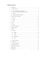
One of the most advanced multi-interface solutions is SUB-20 Multi Interface USB
Adapter [Fig. 1, 2] produced by Dimax [1]. SUB-20 is a versatile and efficient bridge device
providing simple interconnect between PC (USB host) and different HW devices and systems
via popular interfaces such as I2C, SPI, RS232, RS485, SMBus, ModBus, IR and others. It is
also a full "any to any" converter between all supported interfaces and I/O features. SUB-20 is a
powerful I/O controller with 32 GPIOs, 8 analog Inputs, PWM outputs, LCD, LEDs and push
buttons. SUB-20 system includes software package containing driver, API Library, GUI and
Command Line based applications, C,C++,C#,VB.net sample code and documentation. SUB-20
can be used with PC running Windows 2000/XP/Vista, MacOS, Unix/Linux. It also supports NI
LabVIEW.
Built-in I2C interface can be clocked from 500Hz up to 440 kHz and work as master
or/and slave on the bus. It supports multi-master arbitration and supports clock synchronization
support for wait states. The hardware part includes noise suppression circuitry which rejects
spikes on bus lines. User can also configure pull-ups and I2C bus voltage.
SPI master clock may be set to values ranging from 125 kHz up to 8MHz. User can
configure phase, polarity and select MSB first or LSB first transfer. Hardware have level
4
translators on SPI lines and supports SPI voltage range from 1.5V to 5.5V. There are also 5
separate Slave Select (Chip Select) outputs with configurable waveforms.
RS232 and RS485 baud rates can be configured by user. Frame length can be set to
5,6,7,8 or 9 bits. The transmission may be performed with 1 or 2 stop bits. Parity check may be
enabled or disabled; if enabled it can be even or odd. There is noise filtering implemented,
including false start bit detection and digital low pass filter.
SUB-20 is offered in a few versions which differ in number of supported interfaces.
Prices range from $79 to $114.
Fig. 1. SUB-20 Multi Interface USB Adapter
Fig. 2. Block diagram of SUB-20
5
2.2 U2C-11 PC-I2C/SPI/GPIO Interface Adapter
U2C-11 [Fig. 3, 4] is also manufactured by Dimax and is the predecessor of SUB-20
adapter [9]. It’s a flexible multi-level I2C interface with configurable speed up to 400 kbit/s. It
also offers SPI interface with configurable phase, polarity and frequency. There are also up to
20 user configurable GPIOs. The device supports fast and easy in-circuit programming,
configuration and debugging of any I2C capable device. It comes with wide range of ready to
use applications with free source code and offers API for custom software development.
Supported operating systems are: Windows 98/2000/XP and Linux.
U2C-11 supports different I2C clock frequencies. User can choose Fast Mode at 400
kbit/s or Standard mode at 100 kbit/s and less. Standard mode speed can be selected by
software. Low speed will allow to communicate on overloaded I2C bus. The controller offers
high level transactions API (read, write), low level (Start, Stop, ACK) and wire level (SDA and
SCL operations). The I2C interface can work only in master mode.
SPI interface offers byte stream read and write transactions, performed in full duplex
(simultaneous read/write ) mode. User can configure SCLK phase, polarity and frequency.
U2C-11 is priced at $69.
Fig. 3. U2C-11 PC-I2C/SPI/GPIO Interface Adapter
6
Fig. 4. Block diagram of U2C-11
2.3 iCM4011
The iCM4011 [Fig. 5] embedded controller from Ingenia is not designed as typical
adapter [8]. It’s a communication module that can run programs uploaded using built-in
bootloader. It makes it possible to quickly and effectively develop applications requiring
calculation capacities of up to 30MIPS which can communicate using various interfaces: SPI,
I2C, USB, RS485, RS232 & CAN. Thus to serve as multi-interface adapter the iCM4011
requires appropriate program.
The module has dsPIC 16-bit processor (RISC MCU + DSP) with 48 kB of program
FLASH memory, 2048 bytes data RAM, 1024 bytes of data EEPROM. It offers 30 I/O ports
and 9 ADC channels (10 bits/sample). iCM4011 can be powered from USB or external supply.
It has LEDs, motor control features (6 PWM channels, quadrature encoder interface), 5 timers, 4
input capture/compare and brown-out reset.
The price is US$189.00.
7
Fig. 5. iCM4011
2.4 Aardvark I2C/SPI Host Adapter
The Aardvark I2C/SPI Host Adapter [Fig. 6] is a fast I2C bus and SPI bus host adapter
controlled via USB [10]. It allows a developer to interface a Windows, Linux, or Mac OS X via
USB to a downstream embedded system environment and transfer serial messages using the I2C
and SPI protocols.
I2C interface can operate as master or slave. Supports standard mode (100 kHz) and fast
(400 kHz) mode as well as various speeds ranging from 1 kHz to 800 kHz. It supports multimaster arbitration and supports inter-bit and inter-byte clock stretching. Aardvark I2C/SPI Host
Adapter offers synchronous slave transmit and receive. It has software configurable I2C pull-up
resistors and software configurable target power pins to power downstream devices. It supports
repeated start, 10-bit slave addressing and combined format transactions.
SPI interface operates in master or slave mode, with up to 8 Mbps master signaling rate
and up to 4 Mbps slave signaling rate. It offers full duplex master transmit/receive and
asynchronous slave transmit/receive. There are also software configurable target power pins to
power downstream devices and software configurable Slave Select (SS) polarity in master
mode.
The device is described as having GPIO functionality. There are no specialized pins for
that but I2C and SPI pins can be reconfigured for general use, allowing them to be used for
custom signals on target systems. GPIO functionality can also be combined with I2C or SPI to
8
interact with target system. GPIO configuration is cached internally to preserve settings between
operational modes.
Included software for Windows, Linux, and Mac OS X gives full access to all Aardvark
I2C/SPI Host Adapter functionality. User has batch scripting capability with the Aardvark XML
Batch Script language. All transactions in and out of the adapter can be logged. Multiple devices
can be controlled simultaneously. Development API allows to create custom applications in
C/C++, C#, VB, .NET and Python.
The price is 240 €.
Fig. 6. Aardvark I2C/SPI Host Adapter
9
3. Common interface standards
There are several interface standards used commonly in the electronic equipment. They
allow to easily connect two or more devices and interchange data between them.
3.1 RS-232
RS-232 (Recommended Standard 232) is a standard for serial data transmission
connecting between a DTE (Data Terminal Equipment) and a DCE (Data Circuit-terminating
Equipment). It is commonly used in computer serial ports, industrial applications and
measurement equipment. The history of RS-232 backs to early 1960s when standards
committee, today known as the Electronic Industries Association, developed a common
interface standard for data communications equipment. Over the 40+ years since this standard
was developed, the EIA published three modifications, the most recent being the EIA232F
standard introduced in 1997. Besides changing the name from RS232 to EIA232, some signal
lines were renamed and various new ones were defined, including a shield conductor. The most
common version is RS-232C, developed in 1969.
In RS-232, user data is sent as a time-series of bits. In addition to the data lines, the
standard defines a number of control lines used to manage the connection between the DTE and
DCE. Each data or control circuit only operates in one direction, that is, signaling from a DTE
to the attached DCE or the reverse. Since transmit data and receive data are separate circuits, the
interface can operate in a full duplex manner, supporting concurrent data flow in both
directions. The standard does not define character framing within the data stream, or character
encoding.
The RS-232 standard defines the voltage levels that correspond to logical one and
logical zero levels for the data transmission and the control signal lines. Valid signals are plus or
minus 3 to 15 volts - the range near zero volts is not a valid RS-232 level. The standard
specifies a maximum open-circuit voltage of 25 volts: signal levels of ±5 ÷ ±15 V are all
commonly seen depending on the power supplies available within a device. RS-232 drivers and
receivers must be able to withstand indefinite short circuit to ground or to any voltage level up
to ±25 volts. The slew rate, or how fast the signal changes between levels, is also controlled.
For data transmission lines (TxD, RxD and their secondary channel equivalents) logic
one is defined as a negative voltage, the signal condition is called marking, and has the
functional significance. Logic zero is positive and the signal condition is termed spacing.
Control signals are logically inverted with respect to what one would see on the data
transmission lines. When one of these signals is active, the voltage on the line will be between
+3 to +15 volts. The inactive state for these signals would be the opposite voltage condition,
10
between -3 and -15 volts. Examples of control lines would include request to send (RTS), clear
to send (CTS), data terminal ready (DTR), and data set ready (DSR).
Fig. 7. RS-232 signal
Because the voltage levels are higher than typical logic levels, special receiver and
driver circuits are required to translate logic levels. These also protect the device's internal
circuitry from short circuits or transients that may appear on the RS-232 interface, and provide
sufficient current to comply with the slew rate requirements for data transmission.
The standard specifies 20 different signal connections [Fig. 8, 9]. Since most devices
use only a few signals, smaller connectors can often be used. This is why both DB-9 connectors
are popular and DB-25 are seen rarely. Because RS-232 cable connects two devices, DCE and
DTE, role of pins on each end is different. It is shown on the pictures below.
11
Fig. 8. DTE connectors (source: [22])
12
Fig. 9. DCE connectors (source: [22])
3.2 RS-485
The most remarkable feature RS-485 is use of balanced lines. Each signal has a
dedicated pair of twisted wires, with the voltage on one wire equal to the negative, or
complement, of the voltage on the other. The receiver responds to the difference between
voltages. A big advantage of balanced lines is their immunity to noise. This means that long
links can be used and higher bit rates achieved (35 Mbit/s up to 10 m and 100 kbit/s at 1200 m).
RS-485 is widely used in industry for controlling various devices [13].
EIA-485 standard designates the two lines in a differential pair as A and B. At the
driver, a TTL logic-high input causes line A to be more positive than line B, while a TTL logic13
low input causes line B to be more positive than line A. At the receiver, if input A is more
positive than input B, the TTL output is logic high, and if input B is more positive than input A,
the TTL output is logic low [Fig. 10]. Referenced to the receiver’s ground, each input must be
within range -7V to +12V. This allows for differences in ground potential between the driver
and receiver. The maximum differential input (VA-VB) must be no greater than ±6V.
Fig. 10. RS-485 data frame (source: [23])
RS-485 allows to create inexpensive local networks and multidrop communications
links. The recommended arrangement of the wires is as a connected series of point-to-point
(multidropped) nodes, a line or bus, not a star, ring, or multiply-connected network. Ideally, the
two ends of the cable will have a termination resistors connected across the two wires. Without
termination resistors, reflections of fast driver edges can cause multiple data edges that can
cause data corruption. Termination resistors also reduce electrical noise sensitivity due to the
lower impedance, and bias resistors (see below) are required. The value of each termination
resistor should be equal to the cable impedance (typically 120 ohms for twisted pairs).
One twisted pair of wires offers half-duplex transmission. To have full-duplex
communication in RS-485 one has to use two pairs, which gives total five wires, including
ground wire. The RS-485 standard doesn’t specify a protocol or format of data. Usually
encoding typical for RS-232 are used.
3.3 1-Wire
1-Wire is a bidirectional bus developed by Dallas Semiconductor Corp. The name comes from
the fact that single wire is used for both data and clock signal and can be used as power supply
too. Of course ground line is also needed. When a 1-Wire device is powered from the bus it uses
built-in 800 pF capacitor to get supply power. 1-Wire bus is used to connect devices such as
temperature loggers, timers, voltage and current sensors, battery monitors, and memory [Fig.
11]. Each device on the bus has a unique 64-bit serial number. The least significant byte of the
14
serial number is an 8-bit number that tells the type of the device. The most significant byte is a
standard (for the 1-wire bus) 8-bit CRC.
Fig. 11. Devices on 1-Wire bus
Devices connected to 1-Wire bus create a network called MicroLan. There can be only
one master device which initiates all transfers. The Dallas 1-Wire network is physically
implemented as an open drain master device connected to one or more open drain slaves. A
single pull up resistor is common to all devices. It pulls the bus up to 3 or 5 volts, and may
provide power to the slave devices. The master starts a transmission with a "reset" pulse, which
pulls the wire to 0 volts for 480 µs. This pulse resets every slave device on the bus. After that,
any slave device, if present, shows that it exists with a "presence" pulse: it shorts the wire to
ground for at least 60 µs after the master release the bus.
To send "1", the bus master software sends a very brief (1 - 15 µs) low pulse. To send
"0", the software sends a 60 µs low pulse. The falling (negative) edge of the pulse is used to
start a monostable multivibrator in the slave device. The multivibrator in the slave clocks to
read the data line about 30 µs after the falling edge. The slave's multivibrator unavoidably has
analog tolerances that affect its timing accuracy, which is why the output pulses have to be 60
µs long, and the starting pulse can't be longer than 15 µs.
When receiving data, the master sends a 1-15 µs negative pulse to start each bit. If the
transmitting slave unit wants to send a "1", it does nothing, and the wire goes immediately up to
the pulled-up voltage. If the transmitting slave wants to send a "0", it pulls the data line down to
ground for 60 µs.
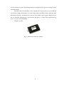
The basic sequence is a reset pulse followed by an 8-bit command, and then data is sent
or received in groups of 8-bits [Fig. 12]. When a sequence of data is being transferred, errors
can be detected with an 8-bit CRC (weak data protection). There are several standard broadcast
commands, and commands addressed to particular devices. The master can send a selection
command, and then the address of a particular device, and then the next command is executed
only by the selected device.
15
Fig. 12. 1-Wire reset, write and read timing diagrams
The bus also has an algorithm to recover the address of every device on the bus. Since
the address includes the device type and a CRC, recovering list of addresses also produces a
reliable inventory of the devices on the bus. The 64-bit address space is searched as a binary
tree. Allowing up to 75 devices to be found per second. To find the devices, the master
broadcasts an enumeration command, and then an address, "listening" after each bit of the
address. If a slave has all the address bits so far, it returns a 0. The master uses this simple
behavior to search systematically for valid sequences of address bits. The process is much faster
than a brute force search of all possible 64-bit numbers because as soon as an invalid bit is
detected, all subsequent address bits are known to be invalid. Enumeration of 10 or 15 devices
finishes very quickly. Location of the devices on the bus is sometimes important as well. For
these situations, the manufacturer has a special device that either passes through the bus, or
switches it off. Software can therefore explore sequential "bus domains."
3.4 I2C
The I2C bus is a multi-master serial computer bus invented by Philips in the early '80s
to connect devices belonging to some set (eg. audio-video devices), modules in a device or
integrated circuits on a PCB [11]. The name I2C translates into "Inter IC". Sometimes the bus is
16
called IIC or I²C bus. The original communication speed was defined with a maximum of 100
kbit per second and many applications don't require faster transmissions. For those that do there
is a 400 kbit fast mode and - since 1998 - a high speed 3.4 Mbit option available. In 2006 fast
mode plus – a transfer rate between 400 kbit/s and 1Mbit/s – has been specified.
I2C is a base for other standards: SMBus, PMBus and TWI. The System Management
Bus (SMBus) is more or less a derivative of the I2C bus. The standard has been developed by
Intel and is now maintained by the SBS Forum. The main application of the SMBus is to
monitor critical parameters on PC motherboards and in embedded systems. SMBus supports
Packet Error Checking (PEC), timeout for transfers, standardized transfer types, ALERT line,
SUSPEND line, power down/up and max. bitrate of 100 kb/s. PMBus is a protocol layer on top
of I2C. It adds timeouts and standards for data transfer formats, however it does not define the
content of transmitted data. TWI stands for Two Wire Interface and for most marts this bus is
identical to I2C. The name TWI was introduced by Atmel and other companies to avoid
conflicts with trademark issues related to I2C. A description of the capabilities of TWI
interfaces can be found in the data sheets of corresponding devices. TWI devices are compatible
to I2C devices except for some particularities like general broadcast or 10-bit addressing. For
the time being there is also no TWI high speed mode [12].
I2C uses only two bidirectional open-drain lines, Serial Data (SDA) and Serial Clock
(SCL), pulled up with resistors. Typical voltages used are +5 V or +3.3 V although systems with
other ( higher or lower) voltages are permitted. The image below shows a simplified equivalent
circuit diagram for an I2C connection between two devices (master or slave). It shows all
factors which are relevant for I2C.
Fig. 13. I2C line with parasitic resistances and capacitances
VCC – I2C supply voltage, ranging from 1.2 V to 5.5 V,
GND – common ground,
SDA – serial data (I2C data line),
SCL – serial clock (I2C clock line),
17
Rp – pull-up resistance (a.k.a. I2C termination),
Rs – serial resistance,
Cp – wire capacitance,
Cc – cross channel capacitance.
The termination resistor Rp pulls the line up to Vcc if no I2C device is pulling it down [Fig.
13]. This allows for features like concurrent operation of more than one I2C master (if they are
multi-master capable) or stretching. In case of concurrent operation master devices can
determine whether the bus is currently idle or not by constantly monitoring SDA and SCL for
start and stop conditions. If the bus is busy, masters delay pending I2C transfers until a stop
condition indicates that the bus is free again. However, it may happen that two masters start a
transfer at the same time. During the transfer, the masters constantly monitor SDA and SCL. If
one of them detects that SDA is low when it should actually be high, it assumes that another
master is active and immediately stops its transfer. This process is called arbitration. Clock
stretching occurs during an SCL low phase when an I2C device holds down SCL to prevent it to
rise high again, enabling it to slow down the SCL clock rate or to stop I2C communication for a
while. This is also referred to as clock synchronization.
Together with the wire capacitance Cp the termination resistor Rp affects temporal
behavior of the signals on SDA and SCL. While I2C devices pull down the lines with open
drain drivers or FETs which can in general drive at least about 10 mA or more, the pull-up
resistor Rp is responsible to get the signal back to high level. Rp commonly ranges from 1 kΩ to
10 kΩ, resulting in typical pull-up currents of about 1 mA and less. This is the reason for the
characteristic sawtooth-like look of I2C signals. In fact, every 'tooth' shows charge of the line on
the rising edge and discharge on the falling edge.
The first byte of an I2C transfer contains the slave address and the data transfer
direction. The address is 7 bits long, followed by the direction bit [Fig. 14]. Like all data bytes,
the address is transferred with the most significant bit first. A seven bit wide address space
theoretically allows 128 addresses - however, some addresses are reserved for special purposes.
Thus, only 112 addresses are available with the 7 bit address scheme. To get rid of this a special
method for using 10-bit addresses is defined.
Fig. 14. I2C address frame (source: [12])
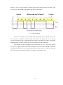
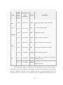
The following table shows I2C addresses reserved for special purposes:
18
10 bit adresses, binary noted, MSB is left
Purpose
0000000 0
General Call
0000000 1
Start Byte
0000001 X
CBUS Addresses
0000010 X
Reserved for Different Bus Formats
0000011 X
Reserved for future purposes
00001XX X
High-Speed Master Code
11110XX X
10-bit Slave Addressing
11111XX X
Reserved for future purposes
In order to prevent address clashes, due to the limited range of the 7 bit addresses, a new
10 bit address scheme has been introduced [Fig. 15]. This enhancement can be mixed with 7 bit
addressing and increases the available address range about ten times. After the start condition, a
leading '11110' introduces the 10 bit addressing scheme. The last two address bits of the first
byte concatenated with the eight bits of the second byte form the whole 10 bit address. Devices
which only use 7 bit addressing simply ignore messages with the leading '11110'.
The
following picture shows the first two bytes of a transfer with a 10 bit address.
Fig. 14. 10-bit addressing (source: [12])
The general call addresses all devices on the bus using the I2C address 0. If a device
does not need the information provided, it simply does nothing. Devices processing the message
acknowledge this address and behave as slave receivers. The master cannot detect how many
devices are using the message. The second byte contains a command. The possible commands
are described in the I2C specification. The value 0 e.g. is a Software Reset.
19
There are four potential modes of operation for a given bus device, although most
devices only use a single role and its two modes:
master transmit — master node is sending data to a slave,
master receive — master node is receiving data from a slave,
slave transmit — slave node is sending data to a master,
slave receive — slave node is receiving data from the master.
The start bit is indicated by a high-to-low transition of SDA with SCL high; the stop bit
is indicated by a low-to-high transition of SDA with SCL high [Fig. 15].
Fig. 15. START and STOP sequences (source: [12])
After sending address byte, if the master wishes to write to the slave then it repeatedly
sends a byte with the slave sending an ACK bit [Fig. 16]. (In this situation, the master is in
master transmit mode and the slave is in slave receive mode.) Similarly when the address byte is
sent and if the master wishes to read from the slave then it repeatedly receives a byte from the
slave, the master sending an ACK bit after every byte but the last one. (In this situation, the
master is in master receive mode and the slave is in slave transmit mode.) The master then ends
transmission with a stop bit, or it may send another START bit if it wishes to retain control of
the bus for another transfer (a "combined message").
Fig. 16. I2C data frame (source: [12])
I2C defines three basic types of message, each of which begins with a START and ends
with a STOP:
-
single message where a master writes data to a slave,
-
single message where a master reads data from a slave,
-
combined messages, when a master issues at least two reads and/or writes to one or
more slaves.
20
In a combined message, each read or write begins with a START and the slave address. After
the first START, these are also called repeated START bits. Repeated START bits are not
preceded by STOP bits, which is how slaves know the next transfer is part of the same message.
Any given slave will only respond to particular messages, as defined by its product
documentation.
3.5 SPI
Serial Peripheral Interface Bus (SPI) is a standard established by Motorola and
supported in silicon products from various manufacturers [14]. It is a synchronous serial data
link that operates in full duplex. Devices communicate using a master/slave relationship, in
which the master initiates the data frame. When the master generates a clock and selects a slave
device, data may be transferred in either or both directions simultaneously. In fact, as far as SPI
is concerned, data are always transferred in both directions. It is up to the master and slave
devices to know whether a received byte is meaningful or not. So a device must discard the
received byte in a "transmit only" frame or generate a dummy byte for a "receive only" frame.
Fig. 17. Single slave SPI configuration (source: [24])
SPI specifies four signals: clock (SCLK); master data output, slave data input (MOSI);
master data input, slave data output (MISO); and slave select (CSS). Figure above shows these
signals in a single-slave configuration. SCLK is generated by the master and input to all slaves.
MOSI carries data from master to slave. MISO carries data from slave back to master. A slave
device is selected when the master asserts its SS signal. If multiple slave devices exist, the
master generates a separate slave select signal for each slave [Fig. 18]. These relationships are
illustrated below. The master generates slave select signals using general-purpose input/output
pins or other logic.
21
Fig. 18. Multi slave SPI configuration (source: [24])
One more interesting configuration involving multiple slaves is daisy chaining [Fig.
19]. With this scheme all data sent by the master is shifted into all devices and all data sent from
each device is shifted out to the next (shown by dotted arrow). For this scheme to work one has
to make sure that each slave uses the clock in the same way and each one has to get the right
number of bits - so there is more work to do in software.
Fig. 19. Daisy-chaining SPI configurations (source: [24])
22
Transmissions normally involve two shift registers of some given word size, such as
eight bits, one in the master and one in the slave; they are connected in a ring. Data is usually
shifted out with the most significant bit first, while shifting a new least significant bit into the
same register. After that register has been shifted out, the master and slave have exchanged
register values. Then each device takes that value and does something with it, such as writing it
to memory. If there is more data to exchange, the shift registers are loaded with new data and
the process repeats.
Transmissions may involve any number of clock cycles. When there is no more data to
be transmitted, the master stops toggling its clock. Normally, it then deselects the slave.
Transmissions often consist of 8-bit words, and a master can initiate multiple such
transmissions if it wishes/needs. However, other word sizes are also common, such as 16-bit
words for touchscreen controllers or audio codecs, like the TSC2101 from Texas Instruments;
or 12-bit words for many digital-to-analog or analog-to-digital converters.
Every slave on the bus that hasn't been activated using its slave select line must
disregard the input clock and MOSI signals, and must not drive MISO. The master must select
only one slave at a time.
In addition to setting the clock frequency, the master must also configure the clock
polarity and phase with respect to the data. Freescale's SPI Block Guide names these two
options as CPOL and CPHA respectively, and most vendors have adopted that convention.
At CPOL=0 the base value of the clock is zero
o
for CPHA=0, data are read on the clock's rising edge (low->high transition) and
data are changed on a falling edge (high->low clock transition),
o
for CPHA=1, data are read on the clock's falling edge and data are changed on a
rising edge.
At CPOL=1 the base value of the clock is one (inversion of CPOL=0)
o
for CPHA=0, data are read on clock's falling edge and data are changed on a
rising edge,
o
for CPHA=1, data are read on clock's rising edge and data are changed on a
falling edge.
While SPI doesn't describe a specific way to implement multi-master systems, some SPI
devices support additional signals that make such implementations possible. However, it's
complicated and usually unnecessary, so it's not used often.
23
3.6 USB
Universal Serial Bus (USB) is a serial bus standard to connect various devices to a host
computer. It was developed to replace legacy standards such as RS-232 and parallel ports and
create universal way of connecting computer peripherals. It has plug and play capabilities,
allows hot swapping and provides power for low-power devices. The design of USB is
standardized by the USB Implementers Forum (USB-IF), an industry standards body
incorporating leading companies from the computer and electronics industries [15].
The USB 1.0 specification was introduced in 1996. It had a data transfer rate of 1.5
Mbit/s (low speed). Later revision 1.1 brought full speed rate of 12 Mbit/s. The USB 2.0
specification was released in April 2000 and was standardized by the USB-IF at the end of
2001. It allowed higher data transfer rate (called hi-speed) of 480 Mbit/s. The USB 3.0
specification was released on November 12, 2008 by the USB 3.0 Promoter Group. It has a
transfer rate of up to 10 times faster than the USB 2.0 version and has been dubbed the
SuperSpeed USB. Equipment conforming with any version of the standard will also work in
most cases – USB 3.0 connector standards have introduced some incompatibilities – with
devices designed to any previous specification.
For transmission of USB signals a braided pair data cable is used with 90Ω ±15%
impedance and wires labeled D+ and D−. Prior to USB 3.0, these collectively use half-duplex
differential signaling to reduce the effects of electromagnetic noise on longer lines. Transmitted
signal levels are 0.0 – 0.3 volts for low and 2.8 – 3.6 volts for high in full speed (FS) and low
speed (LS) modes, and from -10 to +10 mV for low and 360 – 440 mV for high in hi-speed
(HS) mode [16]. In FS mode the cable wires are not terminated, but the HS mode has
termination of 45Ω to ground, or 90Ω differential to match the data cable impedance, reducing
interference of particular kinds. USB 3.0 introduces two additional pairs of shielded twisted
wire and new, mostly interoperable contacts in USB 3.0 cables, for them. They permit the
higher data rate and full duplex operation.
Each data line has 15 kΩ pull-down resistors on host side. When no device is connected,
this pulls both data lines low into the so-called "single-ended zero" state (SE0 in the USB
documentation), and indicates a reset or disconnected connection. When an USB device is
connected, it pulls one of the data lines high with a 1.5 kΩ resistor. This overpowers one of the
pull-down resistors in the host and leaves the data lines in an idle state called "J". In case of
USB 1.x, the choice of data line indicates a device's speed support; full-speed devices pull D+
high, while low-speed devices pull D− high. USB data is transmitted by toggling the data lines
between the J state and the opposite K state. Data is encoded using the NRZI convention; a 0 bit
is transmitted by toggling the data lines from J to K or vice-versa, while a 1 bit is transmitted by
leaving the data lines as-is. To achieve minimum density of signal transitions, USB uses bit
24
stuffing. It is done by inserting extra o bit into the data stream after any appearance of six
consecutive 1 bits. Seven consecutive 1 bits is always an error. USB 3.00 has introduced
additional data transmission encodings [21].
An 8-bit synchronization sequence 00000001 is used on the beginning of USB packets.
After the initial idle state J, the data lines toggle KJKJKJKK. The final 1 bit (repeated K state)
marks the end of the sync pattern and the beginning of the USB frame. A USB packet's end,
called EOP (end-of-packet), is indicated by the transmitter driving 2 bit times of SE0 (D+ and
D− both below max) and 1 bit time of J state. After this, the transmitter ceases to drive the
D+/D− lines and the aforementioned pull up resistors hold it in the J (idle) state. Sometimes
skew due to hubs can add as much as one bit time before the SEO of the end of packet. This
extra bit can also result in a "bit stuff violation" if the six bits before it in the CRC are '1's. This
bit should be ignored be receiver.
Reset on USB bus is done using a prolonged (10 to 20 milliseconds) SE0 signal. USB
2.0 devices use a special protocol during reset, called "chirping", to negotiate the high speed
mode with the host/hub. A device that is HS capable first connects as an FS device (D+ pulled
high), but upon receiving a USB RESET (both D+ and D− driven LOW by host for 10 to 20 ms)
it pulls the D− line high, known as chirp K. This indicates to the host that the device is high
speed. If the host/hub is also HS capable, it chirps (returns alternating J and K states on D− and
D+ lines) letting the device know that the hub will operate at high speed. The device has to
receive at least 3 sets of KJ chirps before it changes to high speed terminations and begins high
speed signaling. Because USB 3.0 use wiring separate and additional to that used by USB 2.0
and USB 1.x, such speed negotiation is not required.
Data on USB bus is transmitted in packets. Initially, all packets are sent from the host,
via the root hub and possibly more hubs, to devices. Some of those packets direct a device to
send some packets in reply. After the sync field described above, all packets are made of 8-bit
bytes, transmitted least-significant bit first. The first byte is a packet identifier (PID) byte. The
PID is actually 4 bits; the byte consists of the 4-bit PID followed by its bitwise complement.
This redundancy helps detect errors. PID byte contains at most four consecutive 1 bits, and thus
will never need bit-stuffing, even when combined with the final 1 bit in the sync byte. However,
trailing 1 bits in the PID may require bit-stuffing within the first few bits of the payload. Packets
come in three basic types, each with a different format and CRC (cyclic redundancy check).
25
USB PID bytes
PID
Type
value
(msbfirst)
Reserved
Transmitted
byte
Name
Description
(lsb-first)
0000
0000 1111
1000
0001 1110
SPLIT
High-speed (USB 2.0) split transaction
0100
0010 1101
PING
Check if endpoint can accept data (USB 2.0)
PRE
Low-speed USB preamble
1100
0011 1100
ERR
Split transaction error (USB 2.0)
Token
Special
Handshake
0010
0100 1011
ACK
Data packet accepted
1010
0101 1010
NAK
Data packet not accepted; please retransmit
0110
0110 1001
NYET
Data not ready yet (USB 2.0)
1110
0111 1000
STALL Transfer impossible; do error recovery
0001
1000 0111
OUT
Address for host-to-device transfer
1001
1001 0110
IN
Address for device-to-host transfer
0101
1010 0101
SOF
Start of frame marker (sent each ms)
1101
1011 0100
SETUP Address for host-to-device control transfer
0011
1100 0011
DATA0 Even-numbered data packet
1011
1101 0010
DATA1 Odd-numbered data packet
0111
1110 0001
DATA2
1111
1111 0000
MDATA
Token
Data
Data packet for high-speed isochronous
transfer (USB 2.0)
Data packet for high-speed isochronous
transfer (USB 2.0)
The characteristic feature of USB system is an asymmetric design, consisting of a host,
a multitude of downstream USB ports, and multiple peripheral devices connected in a tiered-star
topology. Additional USB hubs may be included in the tiers, allowing branching into a tree
structure with up to five tier levels. A USB host may have multiple host controllers and each
26
host controller may provide one or more USB ports. Up to 127 devices, including the hub
devices, may be connected to a single host controller.
USB devices are linked in series through hubs. There always exists one hub known as
the root hub, which is built into the host controller. So-called sharing hubs, which allow
multiple computers to access the same peripheral device(s), also exist and work by switching
access between PCs, either automatically or manually. They are popular in small-office
environments. In network terms, they converge rather than diverge branches.
A physical USB device may consist of several logical sub-devices that are referred to as
device functions. A single device may provide several functions, for example, a webcam (video
device function) with a built-in microphone (audio device function). Such a device is called a
compound device, in which each logical device is assigned a distinctive address by the host and
all logical devices are connected to a built-in hub to which the physical USB wire is connected.
A host assigns one and and only one device address to a function.
USB endpoints actually reside on the connected device: the channels to the host are
referred to as pipes. USB device communication is based on pipes (logical channels). Pipes are
connections from the host controller to a logical entity on the device named an endpoint. The
term endpoint is occasionally used to incorrectly refer to the pipe because, while an endpoint
exists on the device permanently, a pipe is only formed when the host makes a connection to the
endpoint. Therefore, when referring to the connection between a host and an endpoint, the term
pipe should be used. A USB device can have up to 32 active pipes, 16 into the host controller
and 16 out of the controller.
There are two types of pipes: stream and message pipes. A stream pipe is a unidirectional pipe connected to a uni-directional endpoint that is used for bulk, interrupt, and
isochronous data flow while a message pipe is a bi-directional pipe connected to a bi-directional
endpoint that is exclusively used for control data flow. An endpoint is made into the USB
device by the manufacturer, and therefore, exists permanently. An endpoint of a pipe is
addressable with tuple (device_address, endpoint_number) as specified in a TOKEN packet that
the host sends when it wants to start a data transfer session. If the direction of the data transfer is
from the host to the endpoint, an OUT packet, which is a specialization of a TOKEN packet,
having the desired device address and endpoint number is sent by the host. If the direction of the
data transfer is from the device to the host, the host sends an IN packet instead. If the
destination endpoint is a uni-directional endpoint whose manufacturer's designated direction
does not match the TOKEN packet (e.g., the manufacturer's designated direction is IN while the
TOKEN packet is an OUT packet), the TOKEN packet will be ignored. Otherwise, it will be
accepted and the data transaction can start. A bi-directional endpoint, on the other hand, accepts
both IN and OUT packets.
27
Endpoints are grouped into interfaces and each interface is associated with a single
device function. An exception to this is endpoint zero, which is used for device configuration
and which is not associated with any interface. A single device function comprises of
independently controlled interfaces is called a composite device. A composite device only has a
single device address because the host only assigns a device address to a function.
When a USB device is first connected to a USB host, the USB device enumeration
process is started. The enumeration starts by sending a reset signal to the USB device. The
speed of the USB device is determined during the reset signaling. After reset, the USB device's
information is read by the host, then the device is assigned a unique 7-bit address. If the device
is supported by the host, the device drivers needed for communicating with the device are
loaded and the device is set to a configured state. If the USB host is restarted, the enumeration
process is repeated for all connected devices.
The host controller directs traffic flow to devices, so no USB device can transfer any
data on the bus without an explicit request from the host controller. In USB 2.0, the host
controller polls the bus for traffic, usually in a round-robin fashion. The slowest device
connected to a controller sets the speed of the interface. For SuperSpeed USB (USB 3.0),
connected devices can request service from host, and because there are two separate controllers
in each USB 3.0 host, USB 3.0 devices will transmit and receive at USB 3.0 speeds, regardless
of USB 2.0 or earlier devices connected to that host. Operating speeds for them will be set in the
legacy manner.
28
4. Technical assumptions
The goal of this project was to create a device helpful in testing prototype devices. Thus
it was assumed that the controller had to support common interfaces. The following standards
have been chosen:
RS-232 (very simple and still widely used despite of popularity of USB),
without flow control, with speed, parity and word length configured by user,
RS-485 (widely used in industrial applications) two lines, one for receiving and
one for sending data, without flow control, with speed, parity and word length
configured by user,
1-Wire (used for sensors, memory and other simple peripherals) working as
master with regular speed (16 kbps),
I2C (popular standard for connecting ICs and devices) with master or slave
device mode, speed configured by user,
SPI (also very popular, supported by many ICs) working in master or slave
device mode, speed configured by user.
Some devices use parallel port to communicate, with some lines working as inputs and
some as outputs. To support such devices controller needed parallel port consisting of a few I/O
lines. They needed to support following modes:
input floating
input pulled down
input pulled up
open drain output
push-pull output
Not always information is transferred digitally. Sometimes analog values are used. This
is why it was decided that controller has to be equipped with analog to digital converter.
Because nowadays the most popular port in computers is USB, it was chosen as a way to
communicate with the controller. Having access to USB port it was decided that the device
should be powered from it. Thanks to this user doesn’t need external power supply.
To make the device simple and not expensive, modern microcontroller was needed. It
had to offer variety of peripherals without a need for many external components. The device had
also to be small in size.
Not only hardware capabilities of the controller were important but also software for
controlling it. Because the controller had to support multiple interfaces and each of them could
be used to communicate with many different devices, it was necessary to create flexible API so
user can write own software. Such program interface had to be implemented as a library in
poplar programming language. It had to work with kernel mode driver so user doesn’t have to
29
care about low level processes. The API could be sufficient for user but on the other hand it
could be difficult to write custom software from scratch. This is why it was decided that there
had to be some sample applications showing how to use the API.
30
5. Hardware design
To make the hardware simple it was decided to use modern microcontroller having all
necessary peripherals built-in. STM32F103RB belonging to ARM Cortex-M3 family was
chosen. It is low cost, easy to program and supports all needed interfaces except of 1-Wire. It
works with 8MHz quartz oscillator whose frequency is internally multiplied allowing the
microcontroller to work at 72MHz clock. This offers good performance. R3-C3 circuit generates
reset signal for the microcontroller during power-up.
The controller is powered from USB port through popular REG1117F regulator which
delivers 3.3V supply power for all ICs. The regulator is accompanied by capacitors cutting-off
low- and high-frequency distortions. Presence of supply voltage is signaled by LED1.
Because of high voltages required by RS-232 standard, low-power version of MAX232
converter was used. It allows to create RS-232 voltages according to 3.3V signals from
microcontroller and create 3.3V signals for microcontroller according to incoming RS-232
voltages.
In case of RS-485 there are two LT485 converters for each line. They are popular
differential line drivers/receivers. One is configured as receiver and the other one as receiver. In
early design only one line was present and direction of transmission was configured by
software. Later two-line design was introduced to get greater flexibility.
I2C, SPI, 1-Wire, ADC and parallel port are connected directly do their connectors.
Such simple solution was chosen because the microcontroller can work with 5V signals too. 1Wire bus has permanent pull-up resistor. Pull-ups for I2C can be connected by user with
jumpers.
Each line of parallel port is connected to simple circuit allowing to turn on a LED when
logical ―1‖ is present on a line. This allows to easily and instantly check what logical states are
present on parallel port.
31
6. Software
The software is divided into several parts: firmware, kernel mode driver, library and
sample applications. Firmware is a program running on STM32F103RB in the controller. It is
responsible for transmitting data between USB and peripheral interfaces. Kernel mode driver
works on a PC at the lowest level. It communicates with USB port using low level functions and
provides interface for user mode software. Library provides easy to use functions for
communication with interfaces controlled by described device. They also allow to configure the
controller. Sample applications show how to use the library for high level communication.
6.1 Firmware
The firmware for controller was written in C using IAR Embedded Workbench. For
peripherals standard library provided by STMicroelectronics was used (version 3.0.1). Similarly
for USB operations the Full Speed USB library version 3.0.1 from ST was used. Programming
and debugging was done by means of ST Link JTAG interface. #include "stm32f10x_conf.h"
was added to some standard library include files to provide declaration of assert_param macro.
Without that they couldn’t be compiled correctly.
File usb_desc.c contains structures which describe the device from the perspective of
USB protocol. The supported USB version was set to 2.0 and maximum packet size was set to
64 bytes. Vendor ID was set to 0xFEDC and Product ID was set to 0x1234. After plugging the
device operating system can use these values to find appropriate driver. In the device descriptor
one configuration is specified. It informs, that the device is self-powered and consumes
maximum 500 mA. There are two interfaces specified. The first has one interrupt endpoint, the
second has two bulk endpoints. In usb_desc.c there are also specified strings containing
manufacturer and product name. They are presented to a user when operating system founds
new hardware and asks for drivers.
There are two ways of communication with the controller: control transfers and bulk
transfers. Control transfers are used for configuring the controller or push/get small amounts of
data. The following control transfers are supported:
INTERFACE_SELECT
0x10
RS232_LINE_CODING_SET
0x20
RS232_LINE_CODING_GET
0x21
PARPORT_SET
0x40
PARPORT_GET
0x41
PARPORT_CONFIGURE
0x42
WIRE_RESET
0x30
32
WIRE_SEND
0x31
WIRE_RECEIVE
0x32
WIRE_GET_PRESENCE
0x33
WIRE_SEARCH
0x34
ADC_GET
0x50
I2C_SET_7BIT_ADDRESS
0x62
I2C_READ
0x64
I2C_MASTER
0x60
I2C_SLAVE
0x61
SPI_READ
0x70
SPI_MASTER
0x71
SPI_SLAVE
0x72
Control transfers are processed by Virtual_Com_Port_Data_Setup() function or
Virtual_Com_Port_NoData_Setup(). The first one is called for control transfers involving data
transmission, the second one is for control transfers not containing any data, just control transfer
identifier. Virtual_Com_Port_Data_Setup() can call additional routines to access data sent with
control transfers. There is also Virtual_Com_Port_Status_In() function called after control
transfer is finished.
Bulk transfers are used to transmit larger amounts of data. They are used for
communication with 1-Wire, SPI, I2C, RS-232 and RS-485. In case of incoming bulk transfer
the USB library calls EP3_OUT_Callback() routine. It sets count_out variable with value equal
to number of received bytes. Then using PMAToUserBufferCopy() function data from USB
buffer are copied to buffer_out buffer. At the end function SetEPRxValid() is used to mark the
endpoint as ready to receive next piece of data. When the callback function is finished the code
in main() can check value of count_out and process data stored in buffer_out. Sending data is
done in similar way. Data are copied to USB buffer using UserToPMABufferCopy(), their size
is set using SetEPTxCount() and they are marked as ready to be sent using SetEPTxValid().
When the transfer is finished the USB library calls EP1_IN_Callback() which sets usb_sent
variable to 1. This variable helps not o start sending new data until the transfer is in progress.
It must be noted that the PMAToUserBufferCopy() function in official USB library from
STMicroelectronics is flawed [3]. This function copies data from PMA (filled by incoming USB
bulk transfer data) buffer to a buffer specified by user. The problem is that this function always
copies even amount of bytes. This means that when amount of data to be copied is odd, the
function will overwrite one byte which is located just after the area of memory which was meant
to be written. In practice this means that the flawed function can overwrite a variable which is
33
declared after the one the function writes to. It happens when the size of written variable is odd
and equal to the number of bytes to be written. There are two solutions of this problem. The first
one is a fast and ―ugly‖ hack. It is done by declaring a dummy variable just after the one written
by PMAToUserBufferCopy(). With this solution the buggy function would overwrite a variable
which is not used. But this results in two possible problems. First of all there is no guarantee
that the variables would be placed in memory in order of declaration. It depends on particular C
compiler for ARM Cortex microcontroller. The second problem is that this operation has to be
done for all variables accessed by the flawed function, which means that the solution is not
flexible. Thus some better approach is needed. Such an acceptable solution is just to fix the
library by simple modification of PMAToUserBufferCopy(). In this project the second approach
was chosen. The line
*(uint16_t*)pbUsrBuf++ = *pdwVal++;
was replaced following code:
if (((wNBytes % 2)==1) && (n==1))
//odd number and it is the last iteration
*(uint8_t*)pbUsrBuf++ = *pdwVal++;
else
*(uint16_t*)pbUsrBuf++ = *pdwVal++;
6.1.1
RS232
Interrupts generated by USART are handled by function USART1_IRQHandler() from
file stm32f10x_it.c. When data are ready, it calls USART_To_USB_Send_Data() from
hw_config.c. This function receives one byte from USART and puts it in a circular buffer. In
early design, based on sample project provided by STMicroelectronics, data from USART were
put into a regular buffer and then copied to the PMA buffer. Unfortunately this approach was
flawed because of races. During stress tests it turned out that at high data rate transmission
incoming to USART some data were lost. It happened when interrupt from USART raised
during sending data through USB. As this was not acceptable, another approach had to be used.
It was based on consumer-producer idea. To implement it and resolve the problem it was
decided, that putting data into PMA buffer and marking them as ready to send can’t be done in a
routine which works as USART interrupt handler. Instead this routine just puts data into circular
buffer. Sending data to USB is made in main(), after checking that there are data to be sent.
Tests proved that this design assures that no data are lost.
34
6.1.2
RS485
The RS485 protocol is handled in similar way as RS232. The difference is that it uses
USART2_IRQHandler() to handle interrupts and USB_To_RS485_Send_Data() to send data to
RS485 TX line.
6.1.3
1-Wire
In the Peripheral Library from STMicroelectronics there are no routines to support
1-Wire transmissions. In this case custom library was written, it’s store in a file 1wire.c.
The necessary delays required for accurate timings were achieved with SysTick
interrupt, which is generated every microsecond. At each interrupt TimingDelay is decremented.
Creating a delay consists of setting this variable to a specified value representing microseconds
and waiting for the variable to be zeroed. Source code for search ROM algorithm was adapted
an from original Maxim paper [19].
In order to send data from 1-Wire bus to PC the main() function checks value of
wire_buffer_size variable. It is set by USB control command and specifies number of bytes to
be read. When this variable is nonzero the firmware performs appropriate number of reads and
puts them in the USB buffer for bulk transmission. Write is done in a similar way. If value of
count_out in main() is nonzero and currently selected interface is 1-Wire, then data from the
USB buffer are read and send to 1-Wire bus.
6.1.4
ADC
Conversion from analog to digital uses DMA and the code for handling it is quite
simple. Analog to digital converter is configured for work in continuous mode. Thanks to DMA
the result of conversion is copied to ADCConvertedValue variable. A little more explanation is
needed for DMA_PeripheralBaseAddr field in DMA initialization structure. It is set to
0x4001244C. This value comes from the fact that there are 19 registers associated with ADC1
and the conversion result is in the last one. The registers are 32-bit so the offset is 76 (0x4C). By
definition ADC1_BASE = (APB2PERIPH_BASE + 0x2400); APB2PERIPH_BASE =
(PERIPH_BASE + 0x10000); PERIPH_BASE = ((u32)0x40000000). Adding these numbers
together we obtain 0x4001244C, address of the register in which the conversion result is stored.
6.1.5
Parallel port
Parallel port is handled by USB control commands. When PARPORT_GET is received,
the firmware executes GPIO_ReadInputData(). This function is defined in standard peripheral
library and reads data from port C. Read value is returned to PC. Similar thing happens when
35
PARPORT_SET is received. Then the byte received from PC is written to port C using
GPIO_Write()
function
from
standard
peripheral
library.
There
is
also
PARPORT_CONFIGURE control command used to configure selected pins of the C port. With
this command two bytes are transmitted. One byte identifies pins the command applies to. The
second byte specifies mode of the I/Os. This mode can be:
input pulled down, input pulled up,
analog input, input floating,
open drain output, push-pull output, alternate function
open drain and alternate function push-pull. The two bytes are encapsulated in ParPort_Conf
structure variable. Because the PARPORT_CONFIGURE control command is used to set the
same configuration for all specified pins, user has to send as many such commands as many
different modes he wants to use.
6.1.6
I2C
Support for I2C is made using standard peripheral library. I2C_SET_7BIT_ADDRESS
control command is used to set address of a slave device which is sent at the beginning of read
and write operations.
To read data user has to send I2C_READ command with the number of bytes to read.
When firmware receives this command, it executes read operation of the given amount of bytes.
First of all it generates START sequence. Then 7-bit slave address is sent and controller waits as
it become I2C master receiver device. After that it waits for data. When a byte is received the
controller sends acknowledgement. Before receiving last byte acknowledgements are disabled
and STOP sequence is generated. Received data are sent using bulk pipe.
Sending data to I2C bus is done using similar approach. When USB stack receives data
from bulk pipe, the firmware generates START condition and waits to become master device.
Then it sends 7-bit slave address and waits to become master transmitter. After that consecutive
bytes are sent.
6.1.7
SPI
For sending data using SPI interface SPI_SendByte() function was created. At the
beginning the function waits for previous transfer to end by checking SPI_I2S_FLAG_TXE flag.
After that standard peripheral library function SPI_I2S_SendData() is executed to perform one
single byte data transfer. Because on the SPI bus sending and receiving occurs simultaneously
the next thing to do is to receive a byte. Received data is then returned. So SPI_SendByte() not
only sends data but also receives them. This is why SPI_ReadByte() is just a wrapper for
SPI_SendByte(). The only difference is that in case of sending the received value doesn’t matter
and in case of receiving sent data doesn’t matter.
36
6.2 Kernel mode driver
The controller needs a kernel mode driver to allow user level applications for
communication with USB hardware. It was assumed that applications would run on Windows
XP and Vista, thus the driver was written with Windows Driver Foundation framework.
Developing with WDF is a lot easier than with traditional, legacy Windows Driver Model
(WDM) libraries. The primary goal of WDF is "conceptual scalability", that is the
characteristics of only requiring a driver developer to learn a few simple concepts to be able to
write a simple driver, and to be able to incrementally learn more as more complex driver
features are required. This differs noticeably from the WDM that requires driver developers to
be fully familiar with many complex technical details before writing even a simple driver [5].
The driver was written in C using Visual C++ compiler and WDF framework. During
development the Checked environment was used. It allows KdPrint macro to work. It is used to
generate text messages which can be viewed using DebugView utility. When development is
finished then the driver can be compiled using Free environment in which KdPrint and other
debug mechanisms aren’t present.
Driver is compiled to SYS file and is accompanied by appropriate INF file which allows
to install the driver on Windows system [7]. The content of this file is as follows:
[Version]
Signature = "$Windows NT$"
Class=UniversalControllers
ClassGUID={4F81B801-4424-49f0-BB80-B715439DFE6B}
Provider=%MFGNAME%
;CatalogFile=unicon.cat
DriverVer= 06/04/2009
[Manufacturer]
%MFGNAME%=DeviceList
[SourceDisksNames]
1=%INST_DISK_NAME%
[SourceDisksFiles]
unicon.sys=1,,
WdfCoInstaller01005.dll=1,,
[DestinationDirs]
DefaultDestDir=12
ClassInstall32_CopyFiles=11
CoInstaller_CopyFiles = 11
[DeviceList]
%DEV_DESCRIPTION%=DriverInstall,USB\VID_FEDC&PID_1234
[ClassInstall32]
AddReg=ClassInstall32_AddReg
CopyFiles=ClassInstall32_CopyFiles
37
[ClassInstall32_AddReg]
HKR,,,,"Universal devices"
HKR,,Icon,,101
[ClassInstall32_CopyFiles]
[DriverInstall.ntx86]
DriverVer=06/04/2009,0.0.0.1
CopyFiles=DriverCopyFiles
[DriverCopyFiles]
unicon.sys,,,2
[DriverInstall.ntx86.Services]
AddService=unicon,2,DriverService
[DriverService]
ServiceType=1
StartType=3
ErrorControl=1
ServiceBinary=%10%\system32\drivers\unicon.sys
[DriverInstall.ntx86.hw]
AddReg=DriverHwAddReg
[DriverHwAddReg]
;HKR,,SampleInfo,,"Basic registry key"
;;;;;;;;;;;;;;;;;;;;;;;;;;;;;;;;
;; WDF Coinstaller installation
;;;;;;;;;;;;;;;;;;;;;;;;;;;;;;;;
[DriverInstall.ntx86.CoInstallers]
AddReg=CoInstaller_AddReg
CopyFiles=CoInstaller_CopyFiles
[CoInstaller_CopyFiles]
WdfCoinstaller01005.dll,,,2
[CoInstaller_AddReg]
HKR,,CoInstallers32,0x00010000,
"WdfCoinstaller01005.dll,WdfCoInstaller"
[DriverInstall.ntx86.Wdf]
KmdfService = unicon, unicon_wdfsect
[unicon_wdfsect]
KmdfLibraryVersion = 1.0
[Strings]
MFGNAME="Grzegorz Niemirowski"
INSTDISK="Installation Disc"
DEV_DESCRIPTION="Universal USB Controller"
INST_DISK_NAME="Universal
USB
Controller
installation disk"
38
driver
The first section describes the device generally. With Signature entry the driver is
described as designated for Windows NT family. Next two lines describe class of devices to
which the device belongs. As the controller is not a standard device, new class named
UniversalControllers was defined. Globally Unique Identifier (GUID) has been randomly
generated using guidgen.exe tool provided by Microsoft. Provider entry describes producer of
the device and is defined by %MFGNAME% identifier, which value is defined in [Strings]
section. CatalogFile entry is commented out and left in case the driver gets WHQL (Windows
Hardware Quality Labs) certified and is digitally signed. DriverVer defines version of the driver
which is helpful when multiple versions of the driver exist. In Manufacturer section list of
devices is associated with manufacturer. SourceDisksNames lists names of installation disks.
Nowadays it’s unlikely to have drivers on several disks, which was common when floppy disks
were used to distribute software. SourceDisksFiles lists files used by the driver. For this project
there are two files: unicon.sys which is part of the project and WdfCoInstaller01005.dll which is
a library from WDF framework. The latter is used by unicon.sys. DestinationDirs section
informs operating system where to copy the driver files [17]. Here one can use the following
numbers representing directories:
Value
Destination Directory
01
SourceDrive:\pathname (the directory from which the INF file was installed)
10
Windows directory, this is equivalent to %windir%.
11
System directory, this is equivalent to %windir%\system32 for NT-based systems, and
to %windir%\system for Windows 9x/Me.
12
Drivers directory, this is equivalent to %windir%\system32\drivers for NT-based
platforms, and to %windir%\system\IoSubsys on Windows 9x/Me platforms.
17
INF file directory
18
Help directory
20
Fonts directory
21
Viewers directory
23
Color directory (ICM) (not used for installing printer drivers)
24
Root directory of the system disk, this is the root directory of the disk on which Windows
files are installed. For example, if dirid 10 is "C:\winnt", then dirid 24 is "C:\".
25
Shared directory
30
Root directory of the boot disk, also known as "ARC system partition," for NT-based
39
systems. (This might or might not be the same directory as the one represented by dirid
24.)
50
System
directory
for
NT-based
operating
systems,
this
is
equivalent
%windir%\system (NT-based systems only).
51
Spool directory (not used for installing printer drivers − see Printer Dirids)
52
Spool drivers directory (not used for installing printer drivers)
53
User profile directory
54
Directory where ntldr.exe and osloader.exe are located (NT-based systems only)
55
Print processors directory (not used for installing printer drivers)
-1
Absolute path
DefaultDestDir
sets
default
destination
directory
for
copying
to
C:\Windows\System32\drivers. ClassInstall32_CopyFiles specifies location of the files related
to the whole class of devices. It is not used in this project. CoInstaller_CopyFiles applies to the
location of coinstaller files. DeviceList section contains list of devices supported by the driver.
Definition of devices consists of two parts. %DEV_DESCRIPTION% is an identifier of a string
from
[Strings]
section
which
contains
name
of
the
device.
Following
string
―DriverInstall,USB\VID_FEDC&PID_1234” identifies the device. It is described as USB
device with vendor ID set to 0xFEDC and product ID set to 0x1234. There are two ways to
officialy get vendor ID:
1) Become a member of the USB-IF. The annual membership fee is US$4,000.
2) Become a USB-IF non-member logo licensee. Logo licensees are eligible to use the
USB logo in conjunction with products that pass USB-IF compliance testing. In addition, a
vendor ID is assigned to a company if one has not been previously assigned. The licensing fee is
US$2,000 for a two year term (this fee is waived for USB-IF members). As this doesn’t make
sense for prototype devices or manufactured in very small quantities, vendor ID and product ID
have been selected arbitrary [6].
ClassInstall32 section specifies sections which define how to copy class files and make
class registry keys. First one is ClassInstall32_AddReg. It describes the name and icon of the
class in device manager. First entry in this section gives name Universal devices for the class.
The second one sets an icon. Standard icons are located inside setupapi.dll file and are identified
by an index. In this project an icon with index 101 was used. ClassInstall32_CopyFiles section
is empty because the are no class level files. DriverInstall.ntx86 contains information about
40
to
driver version and points to a list of files. DriverCopyFiles contains actual list of driver files to
copy.
The driver runs as system service started when device is plugged in.
DriverInstall.ntx86.Services specifies such a service. DriverService section sets properties of the
service: kernel mode driver, starting on demand, with normal error handling, using unicon.sys
binary. DriverInstall.ntx86.CoInstallers points to sections describing coinstaller files and
registry keys. DriverInstall.ntx86.Wdf specifies driver service and points to the library version
information. Strings section contains various strings used in the INF file.
The INF file is also copied from driver’s directory but it doesn’t contain information
where it should be copied. That’s because it is always copied to C:\Windows\Inf. It is also
copied with different name. The new name starts with oem which is followed by a number. This
number is equal to the number given to previously copied INF file increased by 1. For example
if C:\Windows\Inf contains files from oem0.inf to oem53.inf then new INF file is saved as
oem54.inf.
Because the driver uses WDF framework, the code consists primarily of event handling
routines. DriverEntry() function is called by I/O manager and is the first one called when the
device is plugged in. It is responsible for driver initialization, which includes exporting the
driver's other entry points, initializing certain objects the driver uses, and setting up various perdriver system resources. It is done by calling WdfDriverCreate(). DriverEntry() routine is called
in the context of a system thread at IRQL = PASSIVE_LEVEL.
EvtDeviceAdd() is called whenever the PnP Manager detects a new device has been
connected [4]. This function has to configure and initialize the device. First, power management
callback functions are registered using WdfDeviceInitSetPnpPowerEventCallbacks(). Then a
device instance is created and its PNP capabilities, including capability of so called surprise
removal, which means the device can be unplugged without software detaching. The next
important thing is creating I/O queues. The first one is default queue for non-serialized control
requests and the second one is for serialized requests. The next two queues are for write and
read requests. Finally the device interface is created. The GUID of this interface is {87B8D97F5E6F-4bdf-91DE-196CC5C84158}. When user level application wants to check whether the
USB controller described in this paper is connected, it has to enumerate devices having this
GUID. After enumeration an application can get handle to the device and communicate with it
through the driver.
A driver's EvtDevicePrepareHardware() event callback function is called by the PnP
power manager after it has assigned hardware resources to the device and after the device has
entered its uninitialized D0 state. This function performs any operations that are needed to make
a device accessible to its driver. First step is initialization of USB interface. There are two USB
interfaces exposed by the controller so they are enumerated by the driver. There is only one
41
USB configuration exposed so the driver just selects it. The second step is enumeration of USB
pipes contained in USB interfaces. Driver gets handle to interrupt pipe from the first interface
and to bulk input and output pipes from the second interface. In the third step power
management is initialized. At the end the driver configures continuous reader for bulk in pipe.
This is a mechanism provided by WDF framework which ensures that no incoming data would
be lost. Continuous reader is going to get the USB Request Block completion from the device at
DISPATCH_LEVEL and immediately resubmit it. While this is happening, all of user mode
code is preempted (which runs at PASSIVE_LEVEL), so reading from bulk in pipe has very
high priority [18].
There are also two callback functions connected to power events. The first one is
EvtDeviceD0Entry() which is called when the device is either started or woken up, just after
EvtDevicePrepareHardware(). It is responsible for starting continuous reader, previously
configured by EvtDevicePrepareHardware() event. Similarly EvtDeviceD0Exit() is called when
the device is powered down, for example when unplugged. This routine is responsible for
stopping continuous reader.
When user mode application wants to read data from the driver, EvtDeviceIoRead() is
called. Initially this function was sending request for reading from USB bulk in pipe. During
tests it turned out that it’s not effective solution due to loss of data when controller sent
information with high data rate. Thus in the final version of the driver data are read from 64kB
buffer which is filled by WDF continuous reader in EvtUsbDeviceInterrupt() callback function.
EvtDeviceIoWrite() is called when user mode application makes write request. It sets
the completion routine and starts USB request using bulk out pipe. When the USB write
transaction is finished the completion routine is called and user mode write function returns.
The driver supports not only read and write request but also control requests. They are
used to send commands which can read or write small amounts of data. They can also be not
connected to any data transfer.
Every control request is initially processed by EvtDeviceIoControlEntry() callback
function. Some requests can be processed in the driver only and can be processed directly. The
rest must be processed by the controller so they have to be sent through USB. To do this they
are directed to a serialized queue and processed by another callback function:
EvtDeviceIoControlSerial(). In this routine control requests can be further processed by three
different functions according to transmitted data. If there is no additional data associated with
the request it is processed by IoCtlNoDataCommand(). If there is some data to transmit
IoCtlGetDataCommand() or IoCtlSetDataCommand() is called, depending on whether the
control request is a getter or setter.
It must be noted that control commands have different codes visible for user mode
applications and different for transmitting trough USB. Codes for applications (IOCTL codes)
42
are defines in public.h using CTL_CODE macro. Device type value is set to 65500, which
belongs to range 32768-65535 reserved for use by OEMs and IHVs. Lower values are reserved
for Microsoft. Function codes start from 0x800 because lower values are reserved for Microsoft.
Function codes are consecutive numbers starting from 2048 which is a beginning of range
reserved for OEMs and IHVs. Function codes 0-2047 are reserved for Microsoft.
On the other hand there are codes for actual USB control requests. They are defined in
both firmware and driver. Definitions for the driver are in ProtoTypes.h. They have arbitrary
values, grouped by type of peripheral they are associated with. Translation from IOCTL codes
to USB codes is done in function EvtDeviceIoControlSerial().
6.3 Library
As the driver provides low level functions, libraries provide high level functions. They
operate in user space and communicate with the kernel mode driver. They eliminate the need to
handle low level communication with the device by applications. They allow to easily send and
receive data to/from interfaces offered by the controller. The can be used for example to
enumerate devices connected to interface, address particular device and transfer data to it.
The library for the controller is written in C++ and uses standard WinAPI functions.
Applications using this library should be linked with setupapi.lib.
In order to use the controller user needs a handle to the particular controller connected
to the computer. To find all connected controllers user has to enumerate all devices exposing
appropriate interface. It’s the interface exported by the driver and the GUID of the interface is
{87B8D97F-5E6F-4bdf-91DE-196CC5C84158}.
Enumeration
is
done
by
function
enumerateDevices() defined in the library. It returns vector of identifiers of each connected
controller. Usually only one controller is connected so the vector contains one element. If no
controller is connected then the vector is empty.
When identifier of a controller is obtained it can be used to open the device. One should
open it using OpenDevice() library function. This function returns handle which is used for all
communication with the particular controller. It is passed to library functions. At the end of a
program the device handle should be closed using CloseDevice() library function.
InterfaceSelect() is a function used to configure the controller. It tells it how to behave
when bulk data are sent. When an application writes data using regular write request, they are
sent using bulk pipe. Controller needs to know to which interface it should pass the data. They
can be directed to RS-232, RS-485, SPI, I2C or 1-Wire. Thus InterfaceSelect() should be called
at the beginning of application code.
ParPortSet() – sends one single byte to the parallel I/O port,
43
ParPortGet() – reads one single byte from the parallel I/O port.
ParPortConfigure() – configures individual pins of the parallel I/O port; each pin can be
configured as analog input, floating input, pulled-down input, pulled-up input, open-drain
output, push-pull output, alternate function open-drain or alternate function push-pull,
ADCGet() – reads value from analog to digital converter,
WireReset() – resets 1-Wire bus,
WireGetPresence() – allows to check whether any 1-Wire device was present on a bus
during last reset pulse,
WireReceive() – reads specified number of bytes from 1-Wire bus; the function first
sends read control request with given number of bytes; controller reads those bytes and puts
them in a buffer; the data are then read from the buffer using regular read request.
WireSend() – transmits given amount of data over 1-Wire bus
WireSearch() – enumerates devices connected to 1-Wire bus and returns their 64-bit
identifiers,
RS232SendString() – transmits data from STL string object over RS-232 interface,
RS232Receive() – receives given amount of data from RS-232 and stores them in the
given buffer,
RS232ReceiveString() – wrapper for RS232Receive() library function, which stores
received data in STL string object,
RS232Configure() – configures RS-232 interface, user can set bit rate, stop bits, parity
type and word length,
RS485SendString() – transmits data from STL string object over RS-232 interface,
RS485Receive() – receives given amount of data from RS-232 and stores them in the
given buffer,
RS485ReceiveString() – wrapper for RS232Receive() library function, which stores
received data in STL string object,
RS485Configure() – configures RS-232 interface, user can set bit rate, stop bits, parity
type and word length,
I2CSend7BitAddress() – transmits 7-bit address of slave device over I2C bus,
I2CReceive() – reads specified amount of bytes from I2C bus; the function first sends
read control request with given amount of bytes; controller reads those bytes and puts them in a
buffer; the data are then read from the buffer using regular read request,
I2CSend() – transmits given amount of data to a device connected to I2C bus,
I2CMasterMode() – sets the controller to work as I2C master,
I2CSlaveMode() – sets the controller to work as I2C slave,
SPITransaction() – sends content of input buffer and receives content of output buffer,
SPIMasterMode() – sets the controller to work as SPI master,
44
SPISlaveMode() – sets the controller to work as SPI slave.
6.4 Sample applications
The controller can be used to communicate with various devices. Thus user will often
have to write custom application for a particular type of device. A few sample applications
would be helpful to show how to use the libraries and the controller to interchange data with the
prototype device. The libraries were optimized toward easy data presentation and management
of controller and its interfaces.
1Wire.cpp – the application shows how to communicate with 1-Wire bus. As sample
devices it uses DS18B20 digital thermometers. After obtaining handle to the controller driver
the application performs search and finds all the thermometers connected to the bus. Then it
uses address of each device to send a command triggering temperature measurement. Because
measurement takes some time, application waits one second and then reads the results;
ADC.cpp – simple application which reads a value from the analog to digital converter
every 50 milliseconds;
I2C.cpp – shows how to use I2C bus. It uses M41T00 serial real-time clock. The
address of this device is 0xD0. After addressing the clock for writing current time is sent. After
that the time is read back from clock every 100 milliseconds;
ParPort.cpp – this sample application shows how to configure parallel I/O port, how to
read an write data. It configures pin 3 as input and pins 0 – 2 as outputs. Then it waits until pin 3
is logical ―1‖. When it happens it sets ―1‖ on pin 0. After 100 milliseconds pin 0 is reset and pin
1 is set. The same happens with pin 2 and again with 1 and 0. In other words logical ―1‖ is
moved from pin to pin back and forth. When LEDs are connected to the pins it gives an
impression of a running light point;
RS232.cpp – this example application waits for data from RS-232 port. When it
receives character ‘X’ it sends string specified as command line parameter. The source code also
shows how to configure data rate, word length, parity and stop bits;
RS485.cpp – works in the same way as RS-232 example;
SPI.cpp – this sample shows how to read M25P64 flash memory ID using SPI interface.
The application sends 0x9F byte which is RDID command and then reads three bytes containing
ID of the memory.
45
7. Development and tests
The circuit for the controller was designed using Eagle Layout Editor. When the circuit
was ready the PCB was designed using the same program. Dimensions were set to 100 x 116
mm and number of layers was set to two. Almost all components were in SMD packages. When
the project of the PCB was ready, appropriate GERBER and drill files were generated. They
were sent to SATLAND Prototype company for PCB manufacturing. Electronic components
were bought in TME, Kamami and Semiconductors Bank. Having PCB and all elements the
controller was assembled [Fig. 20].
Fig. 20. Assembled controller
For the controller to work, appropriate software was written: firmware for the
controller, kernel mode driver for Windows XP/Vista, C++ libraries and sample C++
applications.
The controller was checked using the following tests:
The RS-232 interface was tested with a PC equipped with a COM port. This
allowed for easy tests with various data rates up to 115200 bps and different
encoding formats.
46
RS-485 was tested with the same PC but the connection wasn’t direct. Because
the PC didn’t have RS-485 port, a simple circuit with two SN75176 drivers was
assembled. It allowed to test RS-485 the same way as RS-232.
1-Wire interface was used with two DS18B20 digital thermometers. It allowed
to check correctness of ROM search procedure and to check addressing of
individual devices.
ADC was tested with simple potentiometer connected to 3.3V power supply.
I/O was tested with LEDs and switches.
I2C was tested with M41T00 real time clock.
SPI interface was tested with M25P64 flash memory working in SPI mode
47
8. Summary and conclusions
The described controller was assembled, tested and works as expected, according to
assumptions presented in chapter 4. The most difficult task was to write the firmware for the
microcontroller and the kernel mode driver for Windows operating system.
The controller offers features useful in testing prototype devices. Its cost was about 200
PLN, which is a little less than cost of similar commercial solutions. In case of mass production
the cost would be lowered significantly. Thanks to use of versatile microcontroller the device
can be easily extended by more interfaces. It can be used with other operating systems after
writing simple device driver.
Development of the controller was a very good opportunity to learn how to use ARM
Cortex microcontrollers in digital circuits and how to program and debug them. It was also very
important to learn principles of kernel mode driver development using WDF framework. With
ARM Cortex microcontroller and WDF it is very easy to develop various devices
communicating with a PC via USB bus.
The project showed how important is testing. Sometimes a device seems to work
correctly but has serious design flaw which is visible only in special cases, for example with
high data rate. Broad tests can help eliminate such problems. A very interesting thing learned
during development of the controller was that not only code written by the developer can have
bugs but also official libraries and samples supplied by a vendor can be flawed. This means that
even such a code can’t be considered as 100% reliable and must be tested.
48
9. Bibliography
[1] SUB-20 Multi Interface USB Adapter http://www.xdimax.com/sub20/sub20.html
[2] Non-stop USB bulk streaming and USBXpress 3.0.3
http://www.cygnal.org/ubb/Forum9/HTML/001112.html
[3] Bugs in STM libraries http://62.193.238.133/forums-cat-6664-23.html&start=10
[4] Developing a WDF USB Kernel Mode Driver for the OSR USB FX2
http://www.codeproject.com/KB/system/kmdf_osr_usb_fx2.aspx
[5] Building and deploying a basic WDF Kernel Mode Driver
http://www.codeproject.com/KB/system/wdf_kmdf_basic.aspx
[6] Getting a Vendor ID http://www.usb.org/developers/vendor/
[7] INF File Sections and Directives http://msdn.microsoft.com/en-us/library/ms794346.aspx
[8] iCM4011 embedded controller http://www.directindustry.com/prod/ingenia-cat/embeddedcontroller-60145-390953.html
[9] U2C-11 PC-I2C/SPI/GPIO Interface Adapter. USB Solution
http://www.dimax.com.ua/u2c/u2c11.shtml
[10] Aardvark I2C/SPI Host Adapter http://www.iss.se/?id=2031
[11] Official I2C site http://www.i2c-bus.org/
[12] Using the I2C bus http://www.robot-electronics.co.uk/htm/using_the_i2c_bus.htm
[13] Jan Axelson, Serial Port Complete, Lakeview Research, 2000
[14] Introduction to Serial Peripheral Interface
http://www.embedded.com/story/OEG20020124S0116
[15] USB in a NutShell http://www.beyondlogic.org/usbnutshell/usb1.htm
[16] Universal Serial Bus Specification Revision 2.0 April 27, 2000
http://www.usb.org/developers/docs/usb_20_052709.zip
[17] Using Dirids http://msdn.microsoft.com/en-us/library/ms790174.aspx
[18] Writing USB Drivers with WDF
http://www.microsoft.com/whdc/driver/wdf/USB_WDF.mspx
[19] 1-Wire Search Algorithm - AN187 http://pdfserv.maxim-ic.com/en/an/AN187.pdf
[20] Synchronization and Synchronous http://www.pccompci.com/synchronization.html
[21] Universal Serial Bus http://en.wikipedia.org/wiki/Usb
[22] The RS232 Standard
http://www.camiresearch.com/Data_Com_Basics/RS232_standard.html
[23] EIA-485 http://en.wikipedia.org/wiki/Rs-485
[24] SPI Interface details http://www.best-microcontroller-projects.com/spi-interface.html
49
10. Attachments
Circuit diagram
Printed Circuit Board – top layer
Printed Circuit Board – bottom layer
50