1
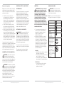
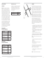
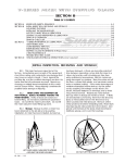
®
Hulk Compactor
Range Manual
Original
Instruction
Manual
Read instructions before operating tools
Models manual is applicable to:
COMPACT24HP
COMPACT110V COMPACT230V COMPACT230VEU
PUBLISHED DATE: 01.02.13
GB
Model Specifications
Evolution Power Tools reserves the right to
make improvements and modifications to the
design and technical specification of this
product without prior notification.
HULK Petrol Engined Compactor
Hulk Electro Compactor
Engine Type
Single cylinder 4 stroke OHV
Engine Power (HP)
2.4 @ 3600 min-1
Spark Plug Replacement
LD E6TC (available from Evolution)
NGK BP6HS
CHAMPION L87YCC
AC DELCO 42FS
Spark Plug Gap
0.028 – 0.031 inches
0.07 – 0.08 mm
Air Filter Replacement
Evolution H1S58
Valve Clearances (cold)
Inlet
0.15 mm 0.006 inches
Exhaust 0.20 mm 0.008 inches
Compaction Force (kN)
10
Vibration (m/sec2)
15.12 K = 1.5
Sound Power Level (LwA)
101 dB(A) K= 3 dB(A)
Sound Pressure Level (LpA) 105 dB(A) K= 3 dB(A)
Recommended Maximum
20
Operator Usage Time (mins)
Oil Type
SAE 10W-30/40
Oil Capacity (litres) 0.25
(pints)
0.5 (US)
Fuel Type
Standard Unleaded Petrol/Gasoline
Fuel Capacity (litres)
1.2
(pints)
2.5 (US)
Weight (kg) (lb)
38 84
Handle Height (during operations - 1020 (40)
extension handle fitted) mm (inches)
Machine Reach (during operations – 1290 (51)
extension handle fitted) mm (inches)
Footprint Width mm (inches)
320 (12-1/2)
Motor
230V or 115V 50/60 Hz 780 W
Motor Speed (min-1)
2860 (no load)
Compaction Force (kN)
5
Recommended Maximum 30
Operator Usage Time (mins)
Sound Power Level (LwA)
98.8 dB(A) K= 3 dB(A)
Sound Pressure Level (LpA) 94 dB(A) K= 3 dB(A)
Vibration (m/sec2)
7.43 K = 1.5
Weight (kg) (lb)
26
57
Handle Height (during operations) mm (inches) 920
(36)
Machine Reach (during operations) mm (inches) 1290
(51)
Footprint Width mm (inches)
320 (12-1/2)
Cable Length Metres (Feet)
10
(33)
Insulation Class
II
This manual was originally written in English.
2
www.evolutionpowertools.com
www.evolutionpowertools.com
3
TABLE OF CONTENTS
PAGE
Specification03
GB
Instruction Manual
Read instructions before operating this tool.
Important Information
05
Evolution Limited Guarantee
05
General Safety Rules
05
Additional Specific Safety Rules
07
Labels and Symbols
11
Machine Overview
12
Getting Started
14
General Operating Advice
19
Maintenance20
Troubleshooting Guides
24
Long Term Storage
26
Optional Accessories
27
Environmental Protection
27
Parts Diagrams & EC - Declaration of Conformities
28
IMPORTANT
Please read these operating and safety
instructions carefully and completely.
For your own safety, if you are uncertain
about any aspect of using this equipment
please access the relevant Technical Helpline,
the number of which can be found on the
Evolution Power Tools website. We operate
several Helplines throughout our worldwide
organization, but Technical help is also
available from your supplier.
WEB www.evolutionpowertools.com/register
Congratulations on your purchase of an
Evolution Power Tools Machine. Please
complete your product registration ‘online’
as explained in the A5 online guarantee
registration leaflet included with this
machine. You can also scan the QR code
found on the A5 leaflet with a Smart
Phone. This will enable you to validate your
machine’s guarantee period via Evolutions
website by entering your details and thus
ensure prompt service if ever needed. We
sincerely thank you for selecting a product
from Evolution Power Tools.
EVOLUTION LIMITED GUARANTEE.
Evolution Power Tools reserves
the right to make improvements
and modifications to the product
design without prior notice.
Please refer to the guarantee
registration leaflet and/or the
packaging for details of the terms
and conditions of the guarantee.
Evolution Power Tools will, within the
guarantee period, and from the original date
of purchase, repair or replace any goods found
to be defective in materials or workmanship.
This guarantee is void if the tool being returned
has been used beyond the recommendations
in the Instruction Manual or if the machine
has been damaged by accident, neglect, or
improper service. This guarantee does not
apply to machines and / or components which
4
www.evolutionpowertools.com
have been altered, changed, or modified
in any way, or subjected to use beyond
recommended capacities and specifications.
Electrical components are subject to respective
manufacturers’ warranties. All goods returned
defective shall be returned prepaid freight
to Evolution Power Tools. Evolution Power
Tools reserves the right to optionally repair or
replace it with the same or equivalent item.
There is no warranty – written or verbal – for
consumable accessories such as (following list
not exhaustive) blades, cutters, drills, chisels
or paddles etc. In no event shall Evolution
Power Tools be liable for loss or damage
resulting directly or indirectly from the use
of our merchandise or from any other cause.
Evolution Power Tools is not liable for any
costs incurred on such goods or consequential
damages. No officer, employee or agent of
Evolution Power Tools is authorized to make
oral representations of fitness or to waive any
of the foregoing terms of sale and none shall
be binding on Evolution Power Tools.
Questions relating to this limited
guarantee should be directed to the
company’s head office, or call the
appropriate Helpline number.
POWER TOOL GENERAL SAFETY
INSTRUCTIONS
(These General Power Tool Safety Instructions
are as specified in BS EN 60745-1:2009 &
EN 61029-1:2009)
WARNING: Read all safety warnings and instructions.
Failure to follow the warnings and instructions
may result in electric shock, fire and/ or
serious injury.
Save all warnings and instructions for
future reference.
The term “power tool” in the warnings refers
to your mains-operated (corded) power tool or
battery-operated (cordless) power tool.
www.evolutionpowertools.com
5
1) General Power Tool Safety Warnings
[Work area safety]
a) Keep work area clean and well lit.
Cluttered or dark areas invite accidents.
b) Do not operate power tools in explosive
atmospheres, such as in the presence of
flammable liquids, gasses or dust. Power tools
create sparks which may ignite the dust or fumes.
c) Keep children and bystanders away
while operating power tool. Distractions can
cause you to lose control.
2) General Power Tool Safety Warnings
[Electrical Safety]
a) Power tool plugs must match the outlet.
Never modify the plug in any way. Do not use
any adapter plugs with earthed (grounded)
power tools. Unmodified plugs and matching
outlets will reduce the risk of electric shock.
b) Avoid body contact with earthed
or grounded surfaces, such as pipes,
radiators, ranges and refrigerators. There is
an increased risk of electric shock if your body
is earthed or grounded.
c) Do not expose power tools to rain or wet
conditions. Water entering a power tool will
increase the risk of electric shock.
d) Do not abuse the cord. Never use the cord
for carrying, pulling or unplugging the power
tool. Keep cord away from heat, oil, sharp
edges or moving parts. Damaged or entangled
cords increase the risk of electric shock.
e) When operating a power tool outdoors,
use an extension cord suitable for outdoor
use. Use of a cord suitable for outdoor use
reduces the risk of electric shock.
f) If operating a power tool in a damp
location is unavoidable, use a residual
current device (RCD) protected supply. Use
of an RCD reduces the risk of electric shock.
3) General Power Tool Safety Warnings
[Personal Safety].
a) Stay alert, watch what you are doing
and use common sense when operating a
power tool. Do not use a power tool while
you are tired or under the influence of
drugs, alcohol or medication. A moment of
6
inattention while operating power tools may
result in serious personal injury.
b) Use personal protective equipment.
Always wear eye protection. Protective
equipment such as dust masks, non-skid
safety shoes, hard hat or hearing protection
used for appropriate conditions will reduce
personal injuries.
c) Prevent unintentional starting. Ensure
the switch is in the off-position before
connecting to power source and or battery
pack, picking up or carrying the tool.
Carrying power tools with your finger on the
switch or energising the power tools that have
the switch on invites accidents.
d) Remove any adjusting key or wrench
before turning the power tool on. A wrench
or key left attached to a rotating part of a
power tool may result in personal injury .
e) Do not overreach. Keep proper footing and
balance at all times. This enables better control
of the power tool in unexpected situations.
f) Dress properly. Do not wear loose
clothing or jewellery. Keep your hair,
clothing and gloves away from moving
parts. Loose clothes, jewellery or long hair can
be caught in moving parts.
g) If devices are provided for the
connection of dust extraction and
collection facilities, ensure that these are
connected and properly used. Use of dust
collection can reduce dust-related hazards.
4) General Power Tool Safety Warnings
[Power tool use and care].
a) Do not force the power tool. Use the
correct power tool for your application.
The correct power tool will do the job better
and safer at a rate for which it was designed.
b) Do not use the power tool if the switch
does not turn it on or off. Any power tool
that cannot be controlled with the switch is
dangerous and must be repaired.
c) Disconnect the power tool from
the power source and/or battery pack
from the power tool before making any
adjustments, changing accessories, or
storing power tools. Such preventative
safety measures reduce the risk of starting the
power tool accidentally.
www.evolutionpowertools.com
d) Store idle power tools out of the reach
of children and do not allow persons
unfamiliar with the power tool or these
Instructions to operate the power tool.
Power tools are dangerous in the hands of
untrained users.
e) Maintain power tools. Check for
misalignment or binding of moving parts,
breakage of moving parts and any other
condition that may affect the power tools
operation. If damaged, have the power
tool repaired before use. Many accidents are
caused by poorly maintained power tools.
f) Keep cutting tools sharp and clean. Properly
maintained cutting tools with sharp cutting edges
are less likely to bind and are easier to control.
g) Use the power tool, accessories and
tool bits etc. in accordance with these
instructions, taking into account the
working conditions and the work to
be performed. Use of the power tool for
operations different from those intended could
result in a hazardous situation.
5) General Power Tool Safety Warnings
[Service]
a) Have your power tool serviced by a
qualified repair person using only identical
replacement parts. This will ensure that the
safety of the power tool is maintained.
SAFETY INSTRUCTIONS FOR HULKSYSTEM PETROL ENGINE
a. Petrol or diesel powered engines must
never be used in unventilated closed spaces.
The exhaust fumes produced are highly
toxic and can cause ‘Carbon Monoxide
Poisoning’ which will cause drowsiness and
ultimately death. It is only permissible to run a
petrol engine indoors if the building can be very
well ventilated and the exhaust fumes can be
captured and ducted to the outside through an
exhaust extraction/scavenger system.
b. The engine should not be run at speeds
that exceed the maximum speed on the
rating plate. Operating an engine at excessive
speeds increases the likelihood of component
failure and consequent accidents.
c. Do not tamper with components that
regulate the engines speed. You may alter
the factory set running parameters.
d. Use only the type of fuel listed in this
Instruction Manual. Using fuel with an
octane rating less than that specified can
lead to excessive engine wear and premature
engine failure.
e. Keep the area around the engine clear,
clean and tidy. Never allow any combustible
material (timber, plastic, cardboard, canvas
etc) near a running engine.
f. Do not use in or near to potentially
explosive atmospheres. Dust laden
atmospheres as can be found in some
industrial buildings (Flour Mills, Timber Mills)
have an explosive potential.
g. Regularly check the fuel system for
leaks. Hoses and unions should be checked
for deterioration or chafing. Check the fuel tank
for damage or for a poorly fitting or worn fuel
cap. Any defects must be rectified before the
engine is used.
h. Always stop the engine and allow it to
cool down before refuelling. Try to avoid any
fuel spillage (often caused by ‘overfilling’ the
tank) and clean up any spilt fuel immediately.
The application of dry sand is an effective way
of neutralising fuel spills. Do not allow sand to
come into contact with any part of the engine.
i. When transporting the engine in a
vehicle ensure that the fuel tap is turned
off. To minimise the risk of fuel spillage the
engine should be secured by ropes etc to the
load area of the vehicle so that it cannot move
during transportation. The engine should be
secured in as level an attitude as possible.
j. For long term storage we recommend
that the fuel system of the engine is
drained. During long term storage additives in
modern fuels can precipitate from the fuel and
block jets and valves in the fuel system.
k. Store the machine in a secure and well
ventilated area. Unauthorised personnel
should not have access to this machine.
SAFETY INSTRUCTIONS FOR FUEL FILLING
a. Select level bare ground, remote from
any buildings as a refuelling station. Ensure
that there is no combustible material in the
immediate vicinity.
www.evolutionpowertools.com
7
b. Smoking, using a naked flame or
producing sparks is strictly forbidden
whilst refuelling. Petrol is highly flammable
and its vapours are combustible.
c. Ensure that the fuel tap is turned ‘off’.
This will ensure that fresh fuel does not ‘flood’
the engines carburettor.
d. The engine must be turned ‘off’ and
allowed to cool before refuelling is
attempted. Inadvertent fuel spillage onto a
hot engine can result in the risk of fire.
e. Any fuel spills must be dealt with
immediately. If petrol contaminates any
clothing the operator must change clothes.
Do not rely on the fuel evaporating from the
clothes. Wash or launder the clothing when
the fuel has evaporated from the material.
f. The use of a funnel during refuelling is
recommended. Use of a funnel will minimise
the risk of fuel spillage.
g. Fill the tank with the correct grade of
unleaded fuel to a level approximately
half way up the fuel filter. Pour the fuel into
the tank carefully and do not try to fill the tank
completely. Pour the petrol slowly to avoid air
traps during filling that could cause fuel spillage.
h. Check the fuel tank cap, and replace as
soon as refuelling is completed. The cap
has a bayonet type connection. Check that it
is correctly installed and seated before slowly
turning on the fuel tap.
i. Check for any fuel leaks throughout the fuel
system. Do not attempt to start the engine if a
fuel leak is suspected. Any detected leak must be
repaired by a suitably qualified technician.
j. Observe all national and/or local
regulations about the storage and use
of petroleum products. All local bye laws
should be observed.
HEALTH ADVICE
WARNING: When using this machine, dust particles will be produced. In some
instances, depending on the materials you
are working with, this dust can be particularly
harmful. You are advised to consider the risks
associated with the materials you are working
with and to reduce the risk of exposure. As
some materials can produce dust that may be
hazardous to your health, we recommend the
8
use of an approved face mask with replaceable
filters when using this machine.
You should always:
• Work in a well-ventilated area.
• Work with approved safety equipment,
such as dust masks that are specially
designed to filter microscopic particles.
WARNING: the operation of any power tool can result in foreign objects being
thrown towards your eyes, which could result
in severe eye damage. Before beginning power
tool operation, always wear safety goggles or
safety glasses with side shield or a full face
shield where needed.
WARNING: If any parts are missing,
do not operate your machine until the
missing parts are replaced. Failure to follow
this rule could result in serious personal injury.
ADDITIONAL SAFETY RULES FOR
HULK COMPACTOR
a. Cordon off the work area. Members of the
public and unauthorised personnel should be kept
at a safe distance from compacting operations.
b. Be completely sure that you know how
to switch the machine ‘off’. If you get into
difficulty during compacting operations it is
important that you can perform an emergency
shutdown of the machine.
c. Never leave the Hulk running and
unattended. The machine vibrates as soon
as it is started, and will also begin to move
forwards. The machine must be shutdown if it
is left unattended.
d. Always switch the engine ‘off’ before
moving the machine around the site. When
moving or transporting the machine the engine
must be switched ‘off’ and preferable cold,
with the fuel tap in the ‘off’ position.
e. As the Hulk engine becomes hot during
use ensure that you do not touch the
engine or allow any combustible material
or clothing to contact the engine during
use. Only touch or service a cold engine.
f. Never remove, alter or tamper with any of
the machines guards. The guards are specially
designed and fitted to provide you with the
www.evolutionpowertools.com
greatest possible protection during operations.
If a guard is missing or damaged do not use the
machine until the guard is repaired or replaced
by a competent technician.
g. Be especially careful to maintain control
when working on a sloping surface. Work
up and down a sloping surface not across it.
h. Where there are a number of different
layers to be compacted on top of each
other, compact each layer separately. This
will ensure the integrity of each layer.
i. Work the Hulk over the work surface
in an organised pattern until the desired
compaction is achieved. This ensures the
safest working practice is maintained.
j. Always carry out the pre-use safety
checks before starting operations. Follow
the guidance in later sections of this Manual.
PPE (Personal Protective Equipment)
Note: If using this equipment on a construction
site it is important that the operator conforms
to any site rules/regulations that may apply.
Consult the site foreman or other responsible
person for details.
a. Wear suitable clothing. This could include
a Boiler Suit or Padded Coverall and Hi Vis
jacket etc.
b. Wear suitable footwear. Safety shoes
with steel toecaps and anti-slip soles are
recommended.
c. Wear suitable Safety Glasses. A Full Face
Safety Shield or Safety Goggles with side
shields which provide protection from thrown
debris is recommended.
d. Protect you hearing. Wear suitable ear
protectors.
e. Wear suitable gloves. High grip gloves are
recommended.
f. Wear respiratory protection. A dust
mask with replaceable filters which provide
protection against fine toxic dust, fibres and
vapours is recommended.
g. Wear a Safety Helmet. The use of a Safety
Hat may be compulsory on construction sites
to protect the operator from potential overhead
dangers.
VEHICULAR TRANSPORTATION
WARNING: This machine requires at least a two man lift.
Prepare the vehicle in advance so that it is
ready to receive the machine. Take great care
to ensure that the machine is not dropped
during loading/unloading.
• Although compact, this machine is heavy. To
reduce the risk of injury, get competent help
whenever you have to lift this machine.
• To reduce the risk of back injury, hold the
machine close to your body when lifting.
Bend your knees so you can lift with your
legs, not your back. Lift by using convenient
areas of the main external frame.
• Lift the machine into the vehicle and secure
in as level an attitude as possible with ropes,
tie down straps etc so that the machine
cannot move during transportation.
Note: Hulk Petrol: It is best and safest practice
when transporting this machine in a vehicle
that there should be no fuel present in the
machines fuel tank.
INTENDED USE OF THIS POWER TOOL
WARNING: This product is a powered Compaction Plate and has been designed
to be used with special Evolution accessories.
Only use accessories designed for use with
this machine and/or those recommended
specifically by Evolution Power Tools Ltd.
This machine can be used to compact surfaces
such as crusher run, small aggregates, soil,
sand and sub base materials etc. When fitted
with the Paving Pad, the Hulk can be used to
compact and settle most types of block paving.
www.evolutionpowertools.com
9
Reasons for Compaction
ELECTRICAL SAFETY – HULK ELECTRO
VIBRATION
SYMBOLS AND LABELS
Disturbed soil, new infill, subbase or blacktop
will have air pockets and small voids within,
which, if not compacted can lead to possible
problems developing.
THE MAINS PLUG
WARNING: When using this machine the operator can be exposed to high
levels of vibration transmitted to the hand
and arm. It is possible that the operator
could develop “Vibration white finger
disease” (Raynaud syndrome). This condition
can reduce the sensitivity of the hand to
temperature as well as producing general
numbness. Prolonged or regular users of
compacting machines should monitor the
condition of their hands and fingers closely.
If any of the symptoms become evident, seek
immediate medical advice.
WARNING: Do not operate machine
if warning and/or instruction labels are
missing or damaged. Contact Evolution Power
Tools for replacement labels.
• As traffic crosses the surface of an
uncompacted area, the loads imposed
press downwards on the material
underneath. This can lead to subsidence
of the top surface as material migrates
downwards to fill the voids.
• A static load (house, garage etc) built
upon uncompacted ground could suffer
subsidence as material beneath it moves.
• Water seeping into material that contains
voids and air pockets can collect in these
spaces and will expand during freezing
conditions and contract again during warm/
dry spells. Expansion and contraction is a
major contributory factor causing damage
to building foundations, and can lead to a
structure needing underpinning.
Compaction increases the density of the
material and hence its ability to withstand static
and dynamic loads. Eliminating air pockets
and small voids reduces the chances of water
ingress collection and subsequent subsidence
due to material expansion and contraction.
This product is fitted with the correct moulded
plug for the designated sales market. The
plug meets the requirements of international
standards, and must be connected to a supply
voltage that is equal to that stated on the
rating label. If the plug or mains supply lead are
damaged they must be replaced with a complete
assembly that is identical to the original. Adhere
to the requirements for mains electricity supply
connection that applies in your Country. If in
doubt consult a qualified electrician.
OUTDOOR USE – HULK ELECTRO
WARNING: For your protection if this tool is to be used outdoors it should not be
exposed to rain, or used in very damp locations.
For added protection use a residual current device
(R.C.D.) that will interrupt the supply if the leakage
current to earth exceeds 30mA for 30ms. Always
check the operation of the residual current device
(R.C.D.) before using the machine.
If an extension cable is required it must be a
suitable type for use outdoors and so labelled.
The manufacturers instructions should be
followed when using an extension cable.
PROHIBITED USE OF THIS POWER TOOL
WARNING: This product is a powered Compaction Plate and must only be
used as such. It must not be modified in any
way, or used to power any other equipment or
drive any other accessories other than those
mentioned in this Instruction Manual.
WARNING: This machine is not intended for use by persons (including children) with
reduced physical, sensory or mental capabilities,
or lack of experience and knowledge, unless
they have been given supervision or instruction
concerning the safe use of the machine by a
person responsible for their safety.
Children should be supervised to ensure
that they do not have access to, and are not
allowed to play with, this machine.
10
www.evolutionpowertools.com
• The measurement and assessment of
human exposure to hand-transmitted
vibration in the workplace is given in:
BS EN ISO 5349-1:2001 and
BS EN ISO 5349-2:2002
• Many factors can influence the actual
vibration level during operation e.g. the
work surfaces condition and orientation
and the type and condition of the machine
being used. Before each use, such factors
should be assessed, and where possible
appropriate working practices adopted.
Managing these factors can help reduce
the effects of vibration:
Handling
• Handle the machine with care, allowing
the machine to do the work.
• Avoid using excessive physical effort on
any of the machines controls.
• Consider your security and stability, and
the orientation of the machine during use.
Note: All or some of the following symbols
may appear in the manual or on the product.
Read the Manual
Wear Ear Protection
Wear Eye Protection
Wear Dust Protection
Warning
CAUTION:
Hot exhaust
Do not touch
CAUTION: This is a
4 stroke engine.
Fill with petrol only.
Do not fill with
diesel oil.
UNLEADED
Petrol Only!
Highly flammable.
Allow motor to cool
before opening
the fuel cap. The
vapour is extremely
flammable and may
ignite on contact with
a hot surface
or flames.
Work Surface
• Consider the work surface material;
its condition, density, strength,
rigidity and orientation.
www.evolutionpowertools.com
11
MACHINE OVERVIEW HULK PETROL
MACHINE OVERVIEW HULK ELECTRO
(4)
(5)
(9)
(7)
(6)
(3)
(3)
(8)
(5)
(12)
(4)
(6)
(13)
(2)
(2)
(11)
(14)
(10)
(1)
12
(1)
1. VIBRATION PLATE
8. ENGINE OIL FILLER/DIPSTICK
1. VIBRATION PLATE
4. ANTI-VIBRATION HAND GRIP
2. FUEL TANK
9. AIR FILTER
2. CROSSBAR/CABLE STORE
5. UPPER SECTION - HANDLE
3. ENGINE ‘ON/OFF’ IGNITION SWITCH
10. SPARK PLUG
3. SAFETY START ‘ON/OFF’ SWITCH
6. MIDDLE SECTION - HANDLE
4. THROTTLE LEVER
11. EXHAUST
5. CHOKE CONTROL
12. ENGINE OIL DRAIN PLUG
6. RECOIL STARTER
13. FAST RUN ADJUSTMENT SCREW
7. FUEL TAP
14. BELT GUARD
www.evolutionpowertools.com
www.evolutionpowertools.com
13
GETTING STARTED
Additional Accessories
ASSEMBLY
UNPACKING
In addition to the standard items supplied with
this machine the following accessories are
also available from the Evolution online shop
at www.evolutionpowertools.com or from
your local retailer.
Your Evolution Hulk needs some minor assembly
and some minor operator adjustments to prepare
the machine for use. If you have the petrol engined
machine complete all assembly before filling the
engine with 0.25L of the recommended service oil.
Caution: This packaging contains sharp
objects. Take care when unpacking. This
machine could require two persons to lift,
assemble and move this machine. Remove
the machine, together with the accessories
supplied from the packaging. Check carefully
to ensure that the machine is in good
condition and account for all the accessories
listed in this manual. Also make sure that all
the accessories are complete. If any parts
are found to be missing, the machine and
its accessories should be returned together
in their original packaging to the retailer. Do
not throw the packaging away; keep it safe
throughout the guarantee period. Dispose
of the packaging in an environmentally
responsible manner. Recycle if possible. Do
not let children play with empty plastic bags
due to the risk of suffocation.
DESCRIPTION
PART No
Hulk Paving Pad
Hulk Pad
ITEMS SUPPLIED HULK PETROL COMPACTOR
Fig. 1
Note: The Handle Extension has an anti-vibration
hand grip which helps the operator to manage the
vibration transmitted by the machine to the hand/
arm of the operator. The Extension Handle should
be fitted for operational purposes, but can be
removed, if convenient, during transportation or
storage. Removing the bottom two thumb screws
and loosening the top two thumb screws allows the
handle extension to be folded forwards for ease of
transportation.
• Carefully slide the Extension Handle over the main
operating handle and align the four (4) holes in the
Extension Handle with the four (4) captive nuts in
the main handle.
• Insert the four (4) ø10 mm thumb screws through
the Extension Handle holes and into the captive
nuts. (Fig. 1)
• Tighten all four (4) thumb screws securely.
DESCRIPTION
QUANTITY
Instruction Manual
1
Handle Extension
1
2. Assembling/attaching the Handle – Hulk Electro
Handle Extension attachment
thumb screws
4
Note: The Hulk Electro Handle consists of four (4)
main parts:
Spark Plug Box Spanner
1
Engine Oil (500 ml bottle)
1
ITEMS SUPPLIED HULK ELECTRO COMPACTOR
14
1. Attaching the Extension Handle – Hulk Petrol
DESCRIPTION
QUANTITY
Instruction Manual
1
Handle attachment thumb
screws (long)
2
Handle attachment thumb
screws (short)
2
Handle cross bar/cable store
1
www.evolutionpowertools.com
• Lower handle (pivoting and factory attached to the
machine).
• Middle section.
• Upper section with ‘On/Off’ safety switch.
• Cross-bar/cable store.
The two long thumb screws are used to attach the
cross-bar/cable store and the middle section of the
handle to the pivoting lower handles.
• Carefully position the cross-bar cable store into its
service position.
Note: The cable pins should face rearwards.
www.evolutionpowertools.com
15
• Carefully slide the Middle Section over the lower
handles and align the holes.
• Insert the long thumb screws through the holes in
the middle handle, through the holes in the lower
handles and screw them into the captive nuts in the
cross-bar/cable store. (Fig. 2)
• Tighten these screws securely.
The two (2) short thumb screws are used to attach the
Upper Section of the handle to the Middle Section.
Fig. 2
• Carefully slide the Upper Section of the handle over
the Middle Section and align the holes.
• Insert the thumb screws through the Upper Section
handle and screw them into the captive nuts within
the Middle Section.
Fig. 4
• Remove the Oil Filler/Level Cap and wipe the
dipstick with a clean dry cloth.
• Pour in the required amount of oil. (approx 0.25L)
• Allow the oil to settle for 10+ seconds.
• View the oil level through the oil filler orifice. The
oil level should be very near the top of the threads
with oil just about to spill out from the crankcase
(the machine must be on a level horizontal surface).
• Insert the dipstick and screw the cap fully ‘home’.
Unscrew the filler cap and withdraw the dipstick.
Visually check the
oil level on the dipstick.
• Adjust as necessary.
• When the level is correct tighten the Oil Filler/Level
Cap securely into the engine casing.
Note: Change the oil according to the Maintenance
Summary Chart (Refer also to MAINTENANCE –
Engine oil replacement)
WARNING: Take care to ensure that the power cable from the Safety Switch down to the motor is
‘free’ and not ‘trapped’ during the assembly process.
Pre – operating checks
Initial filling and checking the oil level –
Hulk Petrol
Note: Before each operation the machine should be
inspected to ensure that all safety features etc, are
working correctly.
WARNING: This machine does not come filled with oil. No attempt to start the engine must be
made until the crankcase is filled to the correct level
with the correct grade of oil.
Fig. 3
Note: Oil (provided) should be poured into the
machine through the Oil Filler/Level Cap. Oil capacity
is approximately 0.25 litre of 10W 30 automotive oil
(available at all good motor factors and most petrol
stations). For some non-temperate climatic areas an
alternative grade of oil may be preferable – consult
your supplier.
The Oil Filler Cap unscrews from the machines engine
casing and incorporates an oil level dip stick. (Fig. 3)
Take care not to spill any oil.
Note: It is important that when checking the oil level
the machine is on a stable, horizontal and level surface
with the engine stopped and cold.
Two index marks are provided on the dipstick.
The oil level should be maintained at or near the
upper index mark.
16
www.evolutionpowertools.com
Fig. 5
• Check that all safety guards are in position and
undamaged.
• Hulk Electro – Check the integrity of the power
cable and plug. If the power cable or plug is
damaged in any way the cable and/or the plug
must be replaced by a competent technician with
identical replacement parts.
• Hulk Petrol - Check all fuel hoses, unions and filler
caps etc for signs of fluid leakage. Any leak detected
must be repaired before operations commence.
• Check the engine oil level and adjust as necessary.
• Check the fuel level and top up as necessary.
• Thoroughly inspect the rest of the machine for
any form of damage particularly to covers, guards,
rubber components etc.
Starting the Hulk Engine
• Turn the fuel tap lever to the ‘On’ position. (Fig. 4)
• Set the choke lever to the ‘Choke On’ position.
(Fig. 5)
www.evolutionpowertools.com
17
Machine Travel – Hulk Petrol
• Press the engine ignition rocker switch to the ‘ON’
(I) position. (Fig. 6)
• Set the throttle lever to maximum. (Fig.7)
Note: Adjusting the speed of the engine alters the
frequency of vibration and also the speed at which the
machine travels forwards. Adjusting the engine speed
controls should only be attempted with the engine
switched off and not running.
Note: The throttle can normally be left in this position
at all times.
Fig. 6
• Steady the Hulk by holding the operating handle at
a convenient point.
• Use your other hand to grip the recoil starter cord
handle. (Fig. 8)
• Pull the recoil starter cord slowly until resistance is
felt indicating that the starter is engaged.
• When resistance is felt pull the cord sharply.
• Continue this procedure until the engine starts.
• Allow the engine to achieve operating temperature.
• Usually the choke can be returned to the ‘off’
(run) position almost immediately when the
engine fires up, but this will depend upon ambient
temperatures, operating conditions etc. and
operator discretion will be required.
• Under some circumstances choke may be needed
even when the engine is warm from a previous
operating cycle. If you experience difficulty in
starting a warm engine:
Note: The Fast Run Screw limits the maximum travel
of the throttle lever and thus controls maximum engine
speed only.
Fig. 9
If you need to alter the maximum engine speed to
increase or decrease the speed of ‘travel’ of the machine:
• Turn the Fast Run Screw (Fig. 9) a little at a time (half a
turn max) clockwise to decrease the engine speed, or
counter clockwise to increase the speed of the engine.
• Ensure that the throttle is set to maximum.
• Start the machine and check the ‘travel’ of the machine
at the new Fast Run Screw setting.
• If necessary stop the machine and adjust further
the Fast Run Screw until the desired ‘travel’ speed
is achieved.
Starting and Stopping the Hulk Electro
Fig. 7
•
•
•
•
Set the choke to the ‘on’ position.
Pull the recoil starter once.
Return the choke to the ‘off’ (run) position.
Pull the recoil starter until the engine fires.
Fig. 10
The Hulk Electro is fitted with a Safety Start ‘On/Off’
switch. The safety interlock prevents the switch lever from
being operated until the safety lock button is depressed.
• Note: The Hulk will begin to vibrate and travel as
soon as the engine is started. The operator should
ensure due diligence when starting this machine.
• Press the safety lock button (Fig. 10) and pull the
switch lever to start the machine.
• Release the switch lever to switch off the machine.
Stopping your Hulk Petrol Engine
Note: Upon release of the switch lever the motor
will stop and the safety lock button will automatically
revert to ‘safe mode’.
• Press the engine ignition rocker switch to the ‘OFF’
(0) position.
• Close the fuel tap.
WARNING: The operator should always be aware of the routing of the power cable to ensure
that it does not become a ‘trip’ or any other form of
hazard, or could be ‘run over’ by the machine.
Fig. 8
18
www.evolutionpowertools.com
www.evolutionpowertools.com
19
WARNING: Be careful. Contact with used engine oil can be harmful. The oil could be very
hot (burn risk) and some operators may experience
irritation if the oil contaminates exposed skin.
The operator should consider wearing mechanics
protective gloves if available. Any skin contaminated
with oil should be washed with soap and copious
amounts of clean water as soon as possible.
GENERAL OPERATING ADVICE
Fig. 11
Fig. 12
• Ensure that bystanders are kept at a safe distance
from compacting operations. If necessary cordon
off the work area and post WARNING notices.
• Plan your work, and the path you intend the machine
to travel, before you start compacting operations.
• Survey the working area before you begin and
remove or otherwise neutralise any obstructions/
obstacles that could pose a danger.
• Ensure you have all the correct PPE and know how
to use it.
• The compactor will travel forwards under its own
power. Gentle inputs from the operator on the
machines handle are all that is necessary to ‘steer’
the machine. The operator should hold the antivibration handle grip with both hands, and the hands
should be positioned as far apart as possible.
• Several passes over the work area may be required
to compact the material to the desired density.
• If the work area is sloped, work up and down the
sloping surface, not across
Check the oil drain plug and its gasket.
Check the oil filler cap and its ‘O’ ring gasket.
Replace any non-serviceable parts.
Re-install the oil drain plug and tighten firmly.
Refill the engine with the correct grade of engine oil
to the correct level.
• Refit the oil filler cap.
• Check for leaks and spillages, and deal with as
necessary.
Note: Used engine oil should be disposed of in an
environmentally safe way. Check with your Local
Authority for the nearest used oil re-cycling facility.
MAINTENANCE
2. Spark Plug - Checking and replacement
HULK PETROL
After approximately 50 hours of operation the spark
plug should be removed for checking, cleaning and
resetting.
Regular maintenance is essential to keep your
machine and its accessories in serviceable condition.
We recommend that only competent operators who
have experience in servicing and maintaining petrol
engines attempt these procedures. If in doubt have
the machine serviced at an Evolution approved
Service Centre.
To remove and reinstall the spark plug:
• Ensure that the engine is switched ‘OFF’ and the
fuel tap is in the ‘OFF’ position.
1. Engine oil replacement
WARNING: The engine should be cold before commencing the spark plug removal procedure.
Engine oil should be replaced after the initial
‘running in’ period and at the intervals specified
in the Service Schedule.
• Pull the HT lead from the spark plug.
• Using a spark plug socket (supplied) remove the
spark plug. (Fig. 13)
Note: Engine oil is easier to replace when the engine
has been run up to temperature and the oil is warm.
A serviceable spark plug in good condition should
exhibit light tan deposits on the plug nose. Remove
these deposits with a stiff brass wire brush.
• Ensure that the engine is positioned on a hard level
surface.
• Remove the oil filler cap. (Fig. 11)
• Place a suitable oil collection pan under the engine.
• Remove the oil drain plug so that the oil can drain
completely from the engine. (Fig. 12)
20
Fig. 13
•
•
•
•
•
www.evolutionpowertools.com
• Check the electrode gap of the plug using a set of
feeler gauges.
• Adjust if necessary. The gap is given in
‘Specification Hulk Petrol’.
• Re-install the spark plug. Be careful that it engages
the threads in the cylinder head correctly.
www.evolutionpowertools.com
21
4. Fuel Tank Filler Filter
• Hand- tighten spark the plug using the supplied
spark plug socket.
• Slide a short, suitable tommy bar through the hole
in the end of the spark plug socket.
• Position the tommy bar so that equal amounts
protrude through either side of the spark plug socket.
• Finally make the gas tight seal by turning the spark plug
socket between ¼ to ½ of a turn. This final fractional
turn will crush the spark plug washer and make a gas
tight seal. Do not overtighten the spark plug.
• Reattach the HT lead to top of the spark plug.
Occasionally visually check the condition of the fuel tank
filler filter (when refuelling is ideal). If there is any sign of
deposit build up, remove the filter from the tank and clean.
• Clean the filter with environmentally friendly water
based degreasing agent and if necessary blow the
fine mesh through with clean, dry compressed air.
• Allow to dry thoroughly before refitting.
• When refitting, ensure that the 2 cut outs on the
top edge of the filter line up with the cut outs in the
fuel tank filler neck.
3. Air Filter
Fig. 14
WARNING: Never run the engine without the air filter element fitted.
Fig. 16
After approximately 50 hours of use the condition of
the air filter should be checked.
Fig. 15
To refit:
• Install the element into the Air Filter Housing.
A new element can fit either way round.
• Replace the Air Filter housing cover.
• Replace the wing nuts and ensure that the cover
is correctly seated and the wing nuts are securely
tightened.
22
www.evolutionpowertools.com
WARNING: Only attempt this procedure with the machine cold and the engine switched ‘off’
and the spark plug cap removed.
Drive belt tension should be checked after the first
4 hours of use and then as specified in the Routine
Maintenance Schedule.
Note: The air filter may require more frequent attention
if the operating environment is especially dusty.
To remove:
• Ensure that the engine is switched ‘OFF’ and the
fuel tap is in the ‘OFF’ position. The engine should
be cold.
• Unscrew the wing nuts from the Air Filter housing
cover and remove it. (Fig. 14)
• Carefully store these parts for later re-installation.
• Remove the Air Filter Element from the housing
for inspection. (Fig. 15) If the paper element of the
air filter shows signs of severe discolouration and
clogging by dirt, dust etc it should be replaced.
5. Checking the Drive Belt Tension
To check the Drive Belt Tension:
• Remove the Belt Guard by removing the three (3)
socket headed screws (Fig. 16) using a hex key and
spanner (not supplied) and store safely for future use.
Fig. 17
Note: These three (3) socket headed screws are
position specific. Note the position of each of the
screws and its related accessories as it is removed
from the machine so that it can be replaced in its
original position.
• Deflection by light finger pressure at the mid-point of
the belt should be approximately 5/6 mm (1/4 inch).
Note: The engine unit of the Hulk is positioned over
four (4) slots on the Engine Mounting Plate. Four (4)
engine mounting bolts are positioned through these
four slots and are screwed from underneath up into the
base of the engine crankcase block. This arrangement
enables the engine to be repositioned on the plate.
• Loosen the four (4) hexagonal headed bolts using a
suitable spanner (not supplied).
• Slide the engine backwards or forwards to alter
the tension of the Drive Belt. An adjustment screw
(Fig. 17) is provided at the front of the engine to aid
precise positioning of the engine.
• When correct tension has been achieved,
securely tighten the engine mounting bolts.
www.evolutionpowertools.com
23
WARNING: Do not adjust the adjustment/tentioning bolt without loosening the four mounting bolts, as this could cause damage to the engine casing.
Note: Care must be taken to ensure that the engine remains ‘square’ and ‘inline’ on the mounting
plate. If the engine were to be in a slightly ‘twisted’ configuration on the mounting plate, the drive belt
and pulleys would be put under ‘distress’ and wear quickly ensue.
TROUBLESHOOTING HULK PETROL
PROBLEM
CAUSE
POSSIBLE REMEDY
Engine will
not start.
No Fuel.
Open Fuel Tap
Fill Fuel Tank.
• Replace the drive Belt Guard and securely tighten the three (3) socket headed screws in their
original positions.
6. Recoil Starting System
The ventilation slots should be kept clean and free from any obstructions.
Remove any foreign matter from the ventilation slots.
HULK PETROL
ROUTINE MAINTENANCE
SCHEDULE
After first 4
hours
Engine Oil Level Check
●
Engine Oil Change
Every
20 hours or
monthly
Every
50 hours or
3 monthly
●
Spark Plug Check
●
●
Fuel Filter Check/Clean
●
Machine
does not
vibrate.
MAINTENANCE HULK ELECTRO
Note: Any maintenance must be carried out with the machine switched off and disconnected
from the power supply.
Check that all safety features and guards are operating correctly on a regular basis. Only use this
machine if all guards/safety features are fully operational.
All motor bearings in this machine are lubricated for life. No further lubrication is required.
Use a clean, slightly damp cloth to clean the plastic parts of the machine. Do not use solvents or
similar products which could damage the plastic parts.
WARNING: Do not attempt to clean by inserting pointed objects through openings in the machines casings etc. The machines air vents should be cleaned using compressed dry air.
24
Remove, clean, reset and replace plug.
Engine cold.
Ensure choke setting is correct.
Engine ‘flooded’ with petrol.
Leave for five (5) mins.
Open choke and fully open the throttle
and try again.
Remove spark plug, clean and replace.
Try again until engine fires.
●
●
Fouled spark plug.
Every
100 hours or
6 monthly
●
Air Filter Replace
Drive Belt Tension
Switch Engine ‘On’.
●
●
(1st change only)
Air Filter Check
Engine switched ‘Off’.
www.evolutionpowertools.com
Air Filter clogged or
contaminated with oil.
Replace Air Filter.
Major Fault.
Contact Agent or Evolution Power Tools
for further advice.
Belt Tension Incorrect.
Adjust the belt tension.
Air Filter Blocked.
Renew the Air Filter.
Eccentric Unit Damaged.
Replace eccentric unit.
Engine speed too slow.
Increase engine speed slightly.
TROUBLE SHOOTING HULK ELECTRO
PROBLEM
CAUSE
POSSIBLE REMEDY
Machine
will not
start.
Supply not switched ‘On’
Switch on supply at the socket.
Fuse in Plug ‘blown’.
Replace fuse and check supply.
Safety Start Button not
depressed preventing
‘On/Off’ actuation.
Depress Safety Start Button
and then pull Start Lever.
Damaged or
broken power cord.
Have the damaged cord replaced by an
identical type fitted by a competent technician.
www.evolutionpowertools.com
25
Use of Optional Evolution Accessories
GENERAL TROUBLESHOOTING GUIDE
PROBLEM
CAUSE
POSSIBLE REMEDY
Paving
blocks
damaged.
Plate in direct contact with
the pavings.
Fit a ‘Hulk Paving Pad’.
Bituminous
surface
flaking
(laminating).
Over compactation.
Remove and relay.
Low travel
speed.
Layer thickness too deep
(plate sinking).
Remove some of the material so that the
layer thickness is reduced.
Engine speed too low.
Increase engine speed slightly.
Moisture content of the
material too high or too low.
Remove the material and adjust the
moisture content.
Engine speed too low.
Increase engine speed slightly.
Petrol
Hulk not
Travelling.
If your Evolution machine is not going to be used for a
period of 4 months or more (e.g. over the winter period)
the operator should consider preparing it for long term
storage. This will keep the engine in optimum condition
for re-commissioning when required.
26
Evolution Paving Pad
Using the Paving Pad allows the operator to compact/settle Driveway Paving, Block Paving and
Patio Slabs etc without the risk of damage or scratching to the decorative top surface of the
pavings by the steel vibration pad.
Note: The Paving Pad has a plate hook to the front, and a plate clamp to the rear.
LONG TERM STORAGE HULK PETROL
Fig. 18
(available as a customer purchase option)
To fit the Paving Pad:
• Hook the Paving Pads plate hook over the front of the vibration plate.
• Clamp the plate clamp over the rear of the vibration plate.
Note: You may find it helpful to remove the large ‘inside’ steel rear clamping plate from the
plastic Paving Pad.
• Remove the two (2) 13mm AF bolts and locking nuts. Store safely for future use.
• Position the plastic Paving Pad on the vibration plate.
• Clamp the rear of the Paving Pad to the vibration plate using the large steel plate clamp and
the two (2) 13mm AF bolts and locking nuts.
• Tighten the 13mm AF nuts and bolts securely.
ENVIRONMENTAL PROTECTION
Waste electrical products should not be disposed of with household waste. Please recycle where
facilities exist. Check with your Local Authority or retailer for recycling advice.
• Drain all the fuel from the fuel tank and carburettor
into a suitable approved container.
• A drain tap can be found underneath the carburettor
float bowl. Loosen this tap to allow the fuel to drain
from the machine. (Fig. 18)
• Tighten the drain tap when all the fuel has been
removed.
• Remove the spark plug.
• Pour approximately one tablespoon of clean engine
oil into the spark plug hole.
• Ensure that the engine ignition switch is in the
‘OFF’ position.
• Gently pull the recoil starter a few times.
• Replace the spark plug.
• Gently pull the recoil starter until resistance is felt
(this will mean that the piston is on its compression
stroke with both valves closed). Stop pulling the
recoil starter.
• Store the engine in a secure, dry and well ventilated
location, under a cover to prevent dust, debris etc
from settling on the machine.
www.evolutionpowertools.com
www.evolutionpowertools.com
27
Parts Diagram
EC DECLARATION OF CONFORMITY
In accordance with EN ISO 17050-1:2004
®
The manufacturer of the product covered by this Declaration is:
Evolution Power Tools, Venture One, Longacre Close, Holbrook Industrial Estate, Sheffield, S20 3FR
The manufacturer hereby declares that the machine as detailed in this declaration fulfils all the
relevant provisions of the Machinery Directive and other appropriate directives as detailed below.
The manufacture further declares that the machine as detailed in this declaration, where
applicable, fulfils the relevant provisions of the Essential Health and Safety requirements.
The Directives covered by this Declaration are as detailed below:
2006/42/EC Machinery Directive.
2004/108/EC. Electromagnetic Compatibility Directive, Annex IV
93/68/EC. The CE Marking Directive.
2011/65/EC. The Restriction of the Use of certain Hazardous Substances in Electrical Equipment (RoHS) Directive
2002/96/EC as amended by 2003/108/EC The Waste Electrical and Electronic Equipment (WEEE) Directive.
And is in conformity with the applicable requirements of the following documents
EN 500 -1:2006
EN 500 -4:2006
Product Details
Description: Hulk Petrol Engined Compactor Plate
Evolution Model No: COMPACT24HP
Factory Model No: XZ-10A/JF154
Brand Name: EVOLUTION
Voltage: Petrol
Input: The technical documentation required to demonstrate that the product meets the requirements of directive has been
compiled and is available for inspection by the relevant enforcement authorities, and verifies that our technical file
contains the documents listed above and that they are the correct standards for the product as detailed above.
Name and address of technical documentation holder.
Signed:
Print: Steven Bulloss: Operations Director
Signed: Print: Lettie Lui: Product Manager
Year that CE was first applied
12
Date: 27/01/13
28
www.evolutionpowertools.com
www.evolutionpowertools.com
29
Parts Diagram
EC DECLARATION OF CONFORMITY
In accordance with EN ISO 17050-1:2004
®
The manufacturer of the product covered by this Declaration is:
Evolution Power Tools, Venture One, Longacre Close, Holbrook Industrial Estate, Sheffield, S20 3FR
The manufacturer hereby declares that the machine as detailed in this declaration fulfils all the
relevant provisions of the Machinery Directive and other appropriate directives as detailed below.
The manufacture further declares that the machine as detailed in this declaration, where
applicable, fulfils the relevant provisions of the Essential Health and Safety requirements.
The Directives covered by this Declaration are as detailed below:
2006/42/EC Machinery Directive.
2004/108/EC. Electromagnetic Compatibility Directive,
93/68/EC. The CE Marking Directive.
2011/65/EC. The Restriction of the Use of certain Hazardous Substances in Electrical Equipment (RoHS) Directive
2002/96/EC as amended by 2003/108/EC The Waste Electrical and Electronic Equipment (WEEE) Directive.
And is in conformity with the applicable requirements of the following documents
EN 500 – 1:2006
EN 500 – 4:2006
EN 60204 – 1:2006
EN 55014-1:2006/+A1:2009
EN 55014-2:1997/+2001/+A2:2008
EN 61000-3-2:2006/+A1:2009/+A2:2009
EN 61000-3-3:2008
Product Details
Description: Hulk Electro Compaction Plate
Evolution Model No: COMPACT110V COMPACT230V COMPACT230VEU
Factory Model No: XZ-5
Brand Name: EVOLUTION
Voltage: 110V or 230V
Input: 50Hz
The technical documentation required to demonstrate that the product meets the requirements of directive has been
compiled and is available for inspection by the relevant enforcement authorities, and verifies that our technical file
contains the documents listed above and that they are the correct standards for the product as detailed above.
Name and address of technical documentation holder.
Signed:
Print: Steven Bulloss: Operations Director
Signed: Print: Lettie Lui: Product Manager
Year that CE was first applied
12
Date: 27/01/13
30
www.evolutionpowertools.com
www.evolutionpowertools.com
31
®
UK HQ
FRANCE HQ
USA HQ
Evolution Power Tools,
Venture One, Longacre Close,
Holbrook Industrial Estate,
Sheffield, S20 3FR, UK
Evolution Power Tools,
61 Avenue Lafontaine, 33560,
Carbon-Blanc,
France
Evolution Power Tools LLC,
8363 Research Drive,
Davenport,Iowa 52806
U.S.A
TEL: +44 (0) 114 251 1022
FAX: +44 (0) 114 247 3339
TÉL: + 33 (0)5 57 30 61 89
FAX: + 33 (0)5 57 30 61 94
TEL: (Toll Free) 866-EVO-TOOL
FAX: 563.386.8010