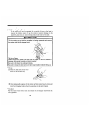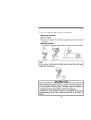
1
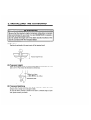
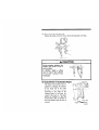
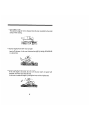
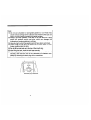
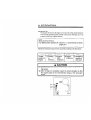
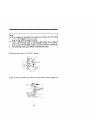
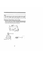
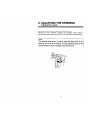
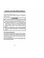
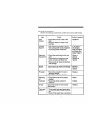
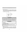
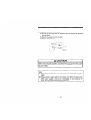
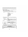
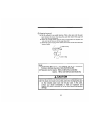
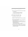
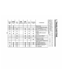
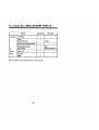
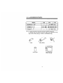
TOHATSU
OUTBOARDS
I
I
5
-
No.00311045-3
YOUR TOHATSU
OWNER REGISTRATION
Upon purchasing
CARD correctly
identifies you as
registmtion.
If this procedure
warrantly~
* : In this manual.
MOTOR
AND IDENTIFICATION
this product, be sure your dealer* fills out the WARRANTY
and completely
and mails it to the distributor.
This card
the legal cwner of the product and serves as your warranty
is not followed,
“dealer”
PRE-DELIVERY
Be sure that the product
Limited
OUTBOARD
your outboard
motor will
always means an authorized
not be covered
TOHATSU
by
dealer.
CHECK
has been checked by the dealer before the delivery
Warranty
This TOHATSU
product is fully guaranteed against defective materials and
workmanship
for the period from the date of purchase, provided
that the
purchase has been registed in accordance with the above.
The limited warranty will not apply to the normal wear and tear of parts.
adjustments. tune-ups, or to any damage caused by:
I)Use
or operation
NOT conforming
to the instmctions
described
in this
owner’s manual,
2) Participation
in or preparation for racing or other competltwe
activities,
3) Water entering the engine or the engine room,
4) Damage of an accidents. collisions,
contact with foreign materials,
or
submenion.
5) Growth of marine orgamsms on motor surfaces~
6) Any other careless use or operation.
7) Normal deterioration.
The limited warranty does not cover maintenance
items. The following
items
are some examples not to be covered by the limited warranty.
spark plugs, anode. trim-tub. propeller,
fuel filter. oil filter. carbon brush.
starter rope, shear-pin, split-pin, b&nut-washer.
wire cable, rubber goods:
pump impeller, oil seal, “0”.ring,
fuel pipe, primer bulb, etc., viny tube.
The limited warranty
will become void if the product has been altered.
modified,
or repaired
by anyone other than a company
or service firm
authorized by TOHATSU.
The limited warranty will cover only your TOHATSU
product and will not
cover the boat the product is mounted on. the trailer, equipment. or accessories
associated with the product.
Serial Number
In the space below. please record the engine’s serial number (indicated both on
the lower motor cover and on the cylinder block). This number will come in
handy in the event of theft or to help in quickly identifying the product type.
Serial Number :
To You, Our Customer:
Thank you for selecting a TOHATSU product. You are now the proud owner of
an erellent outboard engine that will service you for many years to come.
We would like to point out that carefree usage can only be assured on condition
that this manual is read through in its entirety and the maintenance routines
described later in this manual are followed carefully. Should difficulty arise
with the engine. please follow the troubleshooting procedures listed at the end
of this manual. If the problem persists, contact an authorized TOHATSU
Service shop or your dealer.
We hope you will get much enjoyment from this product and wish you good
luck in your boating adventures.
TOHATSU
NOTICE:
CORPORATION
DANGER/WARNING/CAUTION/Note
Before operating your outboard motor, be sure to thoroughly read and
understand this Owner’s Manual and follow all of the instructions shown. Of
particular importance is information preceded by the words “DANGER.”
“WARNING.”
” CAUTION,”
and “Note.” Always pay special attention to such
information to ensure safer and trouble-free operation at all times.
Failure to observe
will result in severe
personal
injury or death.
I
Failure to observe
could result in severe personal
injury or death.
A
Failure to observe
property damage.
CAUTION
could result in minor personal
injury or product
Note:
This instruction provides special information to facilitate
maintenance of the outboard or to clarify important points.
EMERGENCY
or
the use or
STOP SWITCH
The stop switch will cut off the engine when the stop switch line is pulled out.
This line can be attached to the body of the operator. effectively preventing
injuries from the propeller in case he/she falls overboard.
We highly recommend use of the stop switch line because it can save the life of
the operator if somethings bad happens. However, we would also like to point
out the drawbacks of the switch. Accidental activation of the swtch (such as the
line being pulled out in heavy seas) could cause passengers to lose their balance
and even fall overboard, or it could result in loss of power in heavy seas, strong
currents. or high winds. Loss of control while mooring is another potential
hazard.
To prevent such hazardous situations. the 500 mm line is coiled and can
extended to a full 1,300 mm
WARNINGS
As the operation/driver of the boat, you are responsible for the safety of those
aboard and those in other crafts around yours, and for following local boating
regulations. Therefore you should possess thorough knowledge of correct
operation of the boat, its accessories, and the engine. To learn about the correct
operation and maintenance of the engine. please read through this manual
carefully.
It is very difficult for a person standing or floating in the water to take evasive
action should he or she see a power boat heading in his/her direction. even at a
slow speed. Therefore, when your boat is in the immediate vicinity of people in
the water, the engine should be shifted to neutral and shut off.
SERIOUS
INJURY IS LIKELY
IF A PERSON IN THE WATER
MAKES
CONTACT
WlTH A MOVING
BOAT, GEAR HOUSING,
PROPELLER,
OR
ANY SOLID
DEVICE
RIGIDLY
ATTACHED
TO A BOAT
OR GEAR
HOUSING.
It is the operator’s responsibility
to perform all safety checks and to enwre that
all lubrication
and maintenance
instructions
are complied
with for safe
operation. It is also the operator’s responsibility
to return the unit to the local
dealer for periodic inspection.
Correct periodic maintenance and good care of this outboard engine will lessen
the chance of problems and keep overall operating expenses at a minimum.
SERVICING,
REPLACEMENT
PARTS & LUBRICANTS
Only let an authorized TOHATSU
service shop perform sewing or maintenance
on this product. Be sure to use genuine parts and genuine lubricants
or
recommended
lubricants.
MAINTENANCE
As the owner of this outboard engine. you should be acquainted with its correct
maintenance.
Please comply
with
all instructions
on lubrication
and
maintenance.
and return the engine to the dealer or service shop for periodic
inspection at the prescribed intervals.
Troublefree
operation cannot be expended unless the engine receives adequate
periodic maintenance. If maintenance is performed periodically.
it is not likely
that a costly overhaul will ever be required.
USE OF SERVICE
SHOP
When subjecting your TOHATSU
product to a check or repair, please be sure
to use a TOHATSU
dealer authorized by TOHATSU
or a TOHATSU
agent.
CONTENTS
Page
, . SpEClFlCATlONS
2.
NAMES
3.
INSTALLING
.......................................
OF
(1)
PARTS
......................................
THE
Position
OUTBOARD
.3
.........................
-4
............................................
,4
(2) Transom
Height
.4
(3) Tmnsom
Matching ...................................
-4
(4) Securing
the Outboard
-5
......................................
.................................
(5)AdjustmentofOutboardAngle
t,. ,=,,,=L
.I
AND
ENGINE
5. OPERATION.
~~~~~~~~~~~~~~~~~~~~~~~~~~~5
OIL
................................
............................................
(,)Break.Tn..
-9
...........................................
(2) staning
.................
(3) Starting
9
.........................
if Recoil Starter is Out of Order.
.................
(4)Warm.“p...........................................,
(s)ShiftingtoFoward
(6) Reversing.
(,)Spee,,
-7
...................................
16
...........................................
(IO) Mooring
rhe Boat. ...
(12) Precautions
.7
.............................
(9) Stopping
(11) Removing
,7
.......................................
(8)R”nninginShallowWater
and Carrying
during
the Outboard
18
18
..............................
Operation
‘14
6
..........................................
Co&,,,
..~O
..................
..........................
..2 0
‘21
22
6. ADJUSTING
THE STEERING
RESISTANCE
. ..--....23
7. INSPECTION AND MAINTENANCE.-.-...---..-----..24
(1) Daily Inspection
.
.
.
(2) Periodic Inspection
.
.
. .
.29
(3) Preparing the Outboard for Long-Term Storage.
(4) Inspection After Long-Term Storage
‘.
(5)IftheEngineisSubmergedinWater
6. TRO,,BLES,,OOTlNG
.25
. . .32
. .
. .33
,...-..----..........33
..
.
.34
9. TOOL KIT AND SPARE PARTS ..-.-..--...---...--...36
,~.ACCESSORl,=S
1,. WIRING
. . . . ..-.................................37
DIAGRAM..
. . . . . . . . . . . _..
..
. ..
.___.
..~,g
1. SPECIFICATIONS
3.5B2
Model
2.5A2
3.5A2
I
Overall
Overall
Overall
Transom
Weight,
Length, mm
Width, mm
Height, mm
Height, mm
kg S * L
Output, kW
Max. Operation
Range, ‘pm
Idle Speed in Forward Gear, ‘pm
Idle Speed in Neutral Gear, ‘pm
Number of Cylinders
Piston Displacement, mL
Bore & Stroke, mm
Exhaust System
Lubrication System
550
220
s: 955
s: 435
1 195
L: 1,082
L: 562
E
1,100
1,300
1
14.6
41 x 43
Underwater exhaust
Fuel mixture
-
Fuel
Unleaded regular gasoline pump
posted 81 Octane (research octane
rating of 91)
Engine Oil
Genuine or recommended
eneine oil
Engine Oil Mixing
Cooling System
Starting System
Ignition
Spark Plugs
Ratio
Z-stroke
Fuel 50 : Engine Oil 1
Forced water cooling
Recoil starter & pull rope
Flywheel Magneto CD. Ignition
NGK BP6HS-lO/BPR6HS-10
Champion L87YCfRL87YC
(l.Omm gap)
or
Trim Stages
Gear Oil, (II-IL)
Genuine Gear Oil or API GL5, SAE
#80 to #90,
3.5B2: 180, 3.5A2 & 2.5A2: 90
Model
3SB2
Fuel Tank Capacity, L
Approx. 1.4 (Integral
Fuel Consumption
(at full throttle) L/H
Gear Reduction Ratio
Gear Shift
Propeller
(Blade X Diameter
3.542
1.7
13 : 28
F-N
“, - 7”
X Pitch)
2
2.5A2
tank)
1.4
13 : 24
Forward
“F - 6”
(3 x 188 x 145)
2. NAMES
OF PARTS
3. INSTALLING
THE OUTBOARD
: : : : :i:i:i:i:iei;li;;:i:i:i:i:i:i:i:
..~
........... .,.,.,.,.....1~:~:
.,.,.:.,.,.:.::~::.:.:.:.:.:.:.:.:.:.~:..
~~~~~~~~
Be sure that the maximum engine horsepower
rating does not exceed
that recommended
for your boat. It is very DANGEROUS
to operate a
boat with an overpowered
engine.
Do not operate the engine until it has been securely mounted on the
boat in accordance with the instruction below.
(1) Position
Position the outboard at the exact center of the transom board.
Transom
(2) Transom
Height
(3) Transom
Matching
height
of boa1
Install the outboard so that the anticavitation plate is at a level of 30 - 50
mm (1.18 -1.97in.) below the bottom line of the boat.
Be sure that the anti-cavitation plate of the outboard is below the water
surface when running with wide open throttle.
In case the above condition cannot be met due to a bottom shape of your
boat, please consult your dealers
4
(4) Securing
the Outboard
Tighten the clamp screws by hand to secure the outboard to the boat
A CAUTION
During boating, retighten the
acrews from time to time to
ensure safety.
In addition, attach a safety
rope or chain to the outboard
to prevent
possible
loss
overboard.
(5) Adjustment
of Outboard
Angle
The angle of the outboard can be
adjusted by changing the position
of the thrust rod in the holes
provided in the stem brackets,
according to the angle of the
transom board of the boat, the
weight of the load, etc. The angle
should be adjusted so that the
anticavitation plate is parallel to
the water surface when the boat is
running.
5
* Correct angle of trim
The optimum angle of trim is obtained
surface while running.
when the boat is parallel
to the water
* Incorrect angle of trim (bow rises too high)
If the angle of trim is excessive. the bow will rise out of the water and the
speed will decrease. In this case, decrease the angle by setting the thrust rod
in a lower hole.
* Incorrect angle of trim (bow dips into the water)
If the trim angle is too small, the bow will dip into water, the speed will
decrease, and water may enter the boat.
In this case, increase the angle by setting the thrust rod in a higher hole.
4. FUEL AND ENGINE OIL
Fuel
and
oil
Gasoline vapors
are present. an errant spark could
explosion or fire.
0 Do not smoke near gasoline.
l Do not overfill gasoline.
If any gasoline is spilt, wipe it up immediately.
0 Stop the engine before fill gasoline into the fuel tank.
l
Required
Gasoline
cause
an
types
Unleaded gasoline is recommended for outboard motors.
The minimum octane rating should be 87 based on the pump-posted octane
rating method (91 based on the research octane rating method).
Note:
Gasoline containing alcohole, methanol (methyl), or ethanol (ethyl),
may cause:
0 Wear and damage on bearings, piston, piston rings, and cylinder
liners
0 Corrosion
of metal parts
0 Deterioration of rubber parts and plastic parts.
Engine oil
Use genuine engine oil or the other recommended one. that is, TCW3. We
can not recommend any other two-stroke engine oil
Note:
Do not mix different brands of oil. The mixing of different brands, or
different kinds even if the same brand, may cause gelling, resulting in
blockage of filter screens. This may lead to serious engine damage
due to the lack of lubrication.
7
Note:
(1) Do not use unsuitable or poor-grade gasoline or oil. These may
cause serious damage to the outboard and shorten its life span, as
well as causing starting problems and other troubles.
(2) Always use fresh gasoline. Fuel kept in the fuel tank for a long
period will produce varnish and gum, which can damage the
outboard and create problems in running.
(3) Use only fuel in which the gasoline and oil have been well-mixed.
(4) When Filling the fuel tank, be careful that no dust, water or other
foreign matter enters the tank.
(5) Do not fill the fuel tank up to the top of the mouth ring.
(6) After filling the tank, close the tank cap securely.
(7) When carrying the fuel tank, close the air vent screw and fuel cock
securely, and drain the fuel in the carburetor
oil chamber completely by removing the drain plug with a screwdriver.
5. OPERATION
(1) Break-IN
The purpose of break-in the engine is to ensure the initial smooth operation
of the moving and sliding parts (cylinder, piston, gears, bearings. etc.) so as
to protect them from irregular abrasion.
Note:
Break-in period: 5 hours
Fuel (Mixing ratio): Gasoline
Gasoline
25 : Genuine or recommended
Z-stroke
engine oil 1
20 : Other types of Z-stroke engine oil 1
Operate the outboard during the break-in period according to the table below:
Time
Throttle
position &
Engine
speed
0 min. @ Cruising
at
minimum
speed
1 iOmin.@ Approx.
500 3,500 rpm
1
3hrs.-
@ Approx.
4,000 rpm
1
5 hrs. -
@Available to
operate at
wide open
throttle.
A CAUTION
(1) During the break-in period, never run the engine continuously
at
high speed.
(2) After running-in is completed, select the correct propeller so that
the engine speed is the recommended
range at the wide-open
throttle.
I
A CAUTION
(1) If the operator fails to follow the braek-in procedures,
the engine
life may be shortened and engine troubles may occur.
(2) After completing 5 hours of break-in, replace the gear oil with new
oil.
Refer to “Changing the gear oilll in subsection (2). Periodic Inspection.
(2) Starting
A CAUTION
* Do not operate the engine unless the anticavitation plate on the gear
case is underwater.
If the cooling water is not circulating. serious
problems will arise and damage may be caused to the water pump.
engine, etc.
@Fill the fuel tank with the correct fuel mixture. The tank has a capacity of
approx. I.4 literr. permitting the engine to be operated for 30 to 40 minutes.
Be careful not to spill any fuel on board. If any fuel or gasoline is spilled,
wipe it up thoroughly for safety.
@ Loosen the air vent screw on the fuel tank cap (2 - 3 turns).
10
@Make
sure that the shift lever is in the “NEUTRAL”
@Turn
the fuel cock lever to the “OPEN”
position. (3 581 only)
position.
Note:
If fuel is not supplied immediately to the carburetor
(new engine
after cleaning), wait for about 15 seconds for the proper quantity
fuel to flow into the carburetor after opening the fuel cock.
@Set the choke lever to the “CLOSE”
position
or
of
Note:
(1) If the engine is still warm from previous running, set the choke
lever to the “OPEN” position to restart.
(2) When restarting the engine just after the engine has stopped,
never set the choke lever to the ‘“CLOSE” position. If the choke
lever is set to the “CLOSE” position, excess fuel will be supplied to
the carburetor leading to difficulty in starting the engine.
@Set the throttle lever to the “START”
position.
@) Ease out the recoil starter grip slowly until you feel the ratchet engage. then
give it a sharp tug.
12
Note:
* Return the recoil starter grip slowly when the engine has started.
Releasing the starter grip at the extended position may cause a
trouble in the starting system.
Note:
* In cold weather, pull the starter handle 2 or 3 times while moving
the choke lever to choke the engine.
1
up
@When the engine has started. immediately return the choke lever to the
“OPEN” position then move the throttle lever downward to slow speed.
A
l
CAUTION
When the shift lever is at the ‘“NEUTRAL”
position, never move the
throttle lever to medium or high speeds. This may cause serious
damage to the engine by rotating it at excessively
high speed.
(3.582)
13
Note:
* If the engine stops soon after having been started with the choke
lever at the “CLOSE” position, set the choke lever to the “OPEN”
position and perform the starting procedure again.
(3) Starting
if Recoil Starter is Out of Order
Remove the engine cover by releasing the screws, then remove the recoil
stafier from the top of the fuel tank. Wind the spare starter rope clockwise
around the starter pulley about 3 times. and pull the rope to start the engine
in same manner as when starting with the recoil starter.
14
(1) When the engine cover and recoil starter have been removed for
emergency starting, take extreme care that the operator’s clothes
or other items do not get caught in the rope or other engine parts
once the engine starts running.
(2)Never touch the spark plug or high-tension cable when the engine
is running, since they are carrying high-voltage electricity.
(3) Avoid high-speed running for safety. A medium or low speed is
recommended,
taking care not to splash water on the fuel tank or
electrical parts.
(4) Once the engine has been started, never attach the engine cover,
etc. to avoid danger.
(5) If the recoil starter is out of order, have it repaired immediately by
your dealer. Emergency rope starting should be performed only in
the case of emergency.
A CAUTION
(1) Never remove the carburetor cover.
(2) Do not leave the connectors
of the electrical lead wires in a disconnected condition. The engine cannot be stopped if the lead
wire of the stop switch is disconnected.
Never disconnect the lead
wire connector or touch the lead wires while the engine is running.
(3) When removing the engine cover, place the screws, etc. in a bag
to avoid losing them.
(4) Take care not to drop the plug cap cover. It is recommended
to
remove it first.
(5) When starting using an emergency starting rope, make sure that
nobody else is in the vicinity of the engine.
15
(4) Warm-Up
Before operating the boat, allow the engine to run at low speedfor approx.
3 minutes to warm it up and circulate the oil through the engine. If the
engine is not warmed up beforehand. the engine life will be greatly
shortened. During the warn-up operation. confirm that cooling water is
dischargedfrom the check port
A CAUTION
I
I
*If cooling water is not discharged and engine operation is
continued. the engine will overheat and damage may occur.
(5) Shifting
to Forward
(3.582 only)
Reduce the engine speed by the throttle lever down, and move the shift
lever quickly to the “FORWARD” (F) position when the engine speedhas
reachedthe lowest rpm.
I
I
A
CAUTION
It may be dangerous to attempt shifting at high RPM.
Be sure to slow down to trolling or idling rpm before shifting.
I
I
(6) Reversing
Return the throttle lever to the “SLOW” position and when the engine
speed has reached the lowest rpm. move the shift lever to the “NEUTRAL”
(N) position. Stand the steering handle upright and turn the motor 180 O.
Move the shift lever to “FORWARD”
(F) for revelse running,
(3.582 only needs to operate shift lever)
A CAUTION
(1) Before shifting “FORWARD,”
reduce the engine speed to the
idling (low) speed. (3.582 only)
(2) It is dangerous to run at high speed while reversing. Be sure to
operate the engine at low speed.
(3) If the motor hits an obstruction
while reversing,
the shock is
directly applied to the motor and the boat. This may result in the
driver and passangers
being thrown out of the boat and may
damage both the engine and the boat. Operate the engine carefully to avoid hitting any obstruction when reversing.
(7) Speed Control
The speed is controlled by operating the throttle lever. Moving the throttle
lever upward increases the speed, and moving it downward decreases the
speed.
A CAUTION
(1) Quick shifting of the throttle lever is dangerous, and may cause a
serious accident such as throwing the driver and passangers
out
of the boat, etc.
(2) Always decrease the speed of the boat when making a sharp turn.
I7
PROPELLER
SELECTION
A propeller must be selected so that the engine rpm measured
throttle while cruising is within the recommended
range.
For genuine propellers. refer to ACCESSORIES
of this manual.
(13) Running
in Shallow
at wide
open
Water
Always proceed at a slow speed in shallow
motor due to hitting underwater obstacles.
water to prevent damage
to the
(9) Stopping
@Reduce
the engine speed to idling rpm, and release the lock of the stop
switch or push the stop switch until the engine stops completely.
@ Close the fuel cock and air vent screw on the fuel tank cap.
18
(1) This stop switch is provided for the safety of the driver. If the lock
is released from the stop switch. the engine will stop. The engine
will not start if the lock is in released condition. The emergency
stop line should be connected to the driver’s wrist, so that the
engine will shut down if the emergency stop line is disconnected
from the switch in the event of an accident such as the driver being
thrown overboard or the boat capsizing.
(2) Be careful not to entangle the emergency stop line when operating
the handle or while running in reverse. If the lock is released when
running at high speed, the engine and the boat will stop suddenly.
This is dangerous
and may cause injury to the driver and
passangers.
(1) The stop switch should be installed only by your dealer.
(2) Confirm that the stop switch works properly every time
19
before
(10) Mooring
the Boat
If the engine will not be operated for a period of time or the boat is
moored in shallow water. tilt up the motor to prevent damage to the
propeller, gear case. etc. due to hitting rocks in the water or low tide.
A CAUTION
Tilt the motor up so that the propeller
the motor with the tilt stopper knob.
is facing upwards
and secure
Tilt Up or Down
When tilting up or down, be sure that no finger or hand is placed in
between the swivel bracket and stern bracket.
Be sure to tilt down the outboard slowly.
Be sure to close the fuel valve and tank cap breather before tilting up.
*Tilt-up
@ Close the fuel cock and air vent
screw on Ihe fuel tank cap.
@After stopping the engine. tilt the motor up fully toward you by hand and
lock the tilt stopper knob in the tilt-up position on the stem bracket.
* Tilt-down
Pull the motor fully toward you and release the tilt stopper knob from the
tilt-up positions
20
(11) Removing
and
Carrying
the Outboard
1. Removing the motor
0 Stop the engine.
@ Close the fuel cock and air vent screw.
@ Remove the motor from the hull and completely drain the water from the
gear case.
2. Carrying
the motor
Be sure to keep the engine vertical posture whenever you carry the motor.
Note:
If you carry or lay the motor horizontal
higher than the propeller.
posture,
keep the power
head
A CAUTION
When trailering the engine installing on a boat, the motor should be in
a running position fully tilting down. Trailering at tilted up condition of
the motor may cause of damage to the motor, boat, etc. by
unexpected tilt lock release getting a shock when trailering.
If trailering the motor at tilt down position is unavailable, fix the motor
securely using a device (like a transom saver bar) at the tilting up
position.
21
:
(12) Precautions
during
Operetion
Before boating and while at sea. check the weather and sea conditions.
etc. to ensure safety. In the following cases. stop the engine and perform
checks as required:
Condition requiring
emergency stop
Action to be
taken
Items to be checked
* Outboard hits
floating wood, a
rock, etc.
Stop the engine.
Engine rpm suddenly increases due to
a sharp turn, wave
conditions, etc.
Reduce the engine speed and
run at medium
or low speed.
Vinyl sheet, debris,
etc. becomes
entangled in the
propeller.
Stop the engine.
Remove entangled vinyl
sheet, etc.
*Abnormally little or
no cooling water is
discharged.
Stop the engine.
Check whether cooling
water intake port is blocked
and clear as required.
Abnormal vibration
or noise occurs.
Stop the engine.
Check clamp screws, bolts
and nuts for looseness and
propeller for deformation.
* Sudden decrease
in engine rpm
occurs.
Stop the engine.
Check engine overheating,
cooling water discharge,
and propeller for
irregularity.
Star mark(*)
Check damage to the
propeller, shear pin,
propeller shaft, drive shaft
housing, etc.
: Return to the nearest marina or port at the lowest possible speed
to perform the necessary inspections, and have your dealer carry
out repairs if required.
22
6. ADJUSTING THE STEERING
RESISTANCE
Adjust the steering resistance with the slide adjusting screw.
Turning the screw clockwise
increases the resistance, while turning it
counterclockwise
decreases the resistance. This will facilitate smooth steering.
Note:
The steering adjust screw is used to adjust the sliding load of the
steering. but not to fix the steering. If excess tightening given to the
screw may lead a cause of damage to the swivel bracket.
23
7. INSPECTION
Care of your outboard
AND MAINTENANCE
motor
To keep your motor in the best operating condition, it is very important that you
perforrr daily, and periodic, maintenance as suggested in the maintenance
schedules that follow.
A CAUTION
0 Your personal safety and that of your passengers
depends on how
well you maintain your outboard motor. Carefully observe all of the
inspection and maintenance procedures described in this section.
0 The maintenance
intervals shown in the checklist
apply to an
outboard motor in normal use. If you use your outboard motor
under severe conditions such as frequent full-throttle operation or
frequent operation
in brackish
water. maintenance
should be
performed at shorter intervals. If in doubt, consult your dealer for
advice.
0 We strongly recommend
that you use only genuine replacement
parts on your outboard motor. Damage to your outboard arising
from the use of other than genuine parts is not covered under the
warranty.
EPA Emissions
Regulations
EPA (United States Environmental Protection Agency) has emission regulations
and is controling air pollution from new outboard motors. All new motors
manufactured by US are certified to EPA as conforming to the requirements of
the regulations. This certification is depend upon factory standards. Therefore,
factory specifications must be followed when servicing emission related
controls. or making adjustments.
Maintenance.
systems
replacement,
or repair of the emission control devices and
by any marine SI (Spark Ignition) engine
or individual.
may be performed
repair establishment
24
(1) Daily Inspection
Perform
the following
Item
checks before and after use to ensure safe boating
Check
Action if required
Fuel
System
*Check the amount of fuel in the
tank.
*Check for debris or water in the
fuel filter.
Replenish.
Cooling
System
*After starting the engine, confirm
that cooling water is discharged at
the cooling water check port.
If no water is
discharged,
stop the engine
and have your
dealer repair it.
Electrical
Equipment
* Check the spark plug for dirt and
wear.
*Check that the emergency stop
switch functions normally and
make sure the lock plate is present.
* Check cords for loose connections
and damage.
Clean or
replace.
Remedy or
replace.
Recoil
Starter
* Check ropes for wear and damage.
* Check the latchet for engagement.
Replace.
Correct or
replace.
Propeller
l
Check the propeller for bent or
damaged blades.
* Check the split pin is present.
Replace.
Mounting
of
Outboard
* Check the thrust rod for proper
position.
* Check the clamp screws for
tightness.
Adjust.
Anode
Check the anode for wear and/or
deformation.
Replace.
Tools and
Spares
*To be ready tools and spare parts
for replacing spark plugs, propeller,
etc.
* Check if the spare rope is provided.
25
Tighten.
@I Washing with fresh water
When the engine has been used in salt water or polluted water. wash the
exterior and flush the cooling water passage with fresh water. The cooling
water passage is flushed by placing the propeller section of the outboard in a
bucket filled with fresh water, and operating the engine for about 3 minutes
to circulate the water in the passage.
Never start or operate the engine indoors or in any space which is not
well ventilated. Exhaust gas contains carbon monoxide, a colorless
and odorless gas which can be fatal if inhaled for any length of time.
A CAUTION
(1) Set the shiff lever to the “NEUTRAL”
postion before washing,
(3.582 only)
(2) When removing the propeller, remove the plug cap from the spark
plug beforehand for safety.
(3) Wash the evterior of the outboard before long-term storage.
(4) Run the engine at low speed when flushing the cooling system.
@Precautions in cold weather
When the engine has been used in cold weather below 0°C (32°F).
completely drain the cooling water in the engine by standing the engine
vertically to prevent trouble due to freezing. then store it. When mooring the
boat wirh the outboard mounted. leave the propeller section submerged in
the water.
26
@ Replacing the propeller and shear pin
(a) Pull out the split pin from the propeller boss and remove the propeller
from the shaft.
(b) Remove the shear pin from the shaft.
(c) Install a new shear pin.
A CAUTION
When removing
plug for safety.
the propeller, disconnect
the plug cap from the spark
Note:
(1) When removing the plug cap cover, take care not to drop it into the
water.
(2) Always carry a spare split pin and shear pin. When the spare has
been used, supply a new one. A damaged or worn split pin or
shear pin should be replaced with a new one.
27
@Replacing the spark plug
Replace the spark plug if there is dirt or carbon deposits around the
electrode, if the insulator is damaged.
(a) Remove the plug cap cover and remove the spark plug.
(b)To remove the spark plug. turn it counterclockwise
with the socket
wrench provided (2lmm). Tap lightly on the spark plug if it is hard to
(c)When fitting the spark plug. screw it in by hand fint then tighten it using
the socket wrench.
Spark
II
gap
Spark plug
Note:
Tighten the spark plug by i/2 - 314 turn to
secure it after it touches the washer on the
cylinder head.
NGK BPSHS-10. NGK BPR6HS-10
or CHAMPION
L-87YC. RL-67YC (Gap 1 .O)
SParkgaP 1
0.9-l.Omm
(d) Fit the plug cap cover securely so that it will not come loose when the
engine is running.
Never remove the plug cap cover when the engine is running.
It is dangerous to touch the high-tension cable inside the plug cap
cover.
28
I
(2) Periodic
Inspection
-
-
s
s!
0
0
-
0
-
0
-
%
2
$
-
Your outboard
(0)
motor should receive careful, and complete,
mark : Items for which inspection
and the necessary
should be performed by the owner or operator.
mark : Consult your dealer.
inspection
action
(*)
m
The inspection periods shown in this table are applicable only in the case of
normal use. If the outboard is subjected to severe use such as for commercial
purposes. the inspections should be carried out more frequently.
@Replacing the anode
The outboard is equipped with a sacrificial anode on the lower side of the
gear case to protect the motor from corrosion~
Anod
@ Changing the gear oil
...........
.... .,.:.,.,.
........... .,.,.,.,.,.,.
,.....,.,.,.,.,.,.,.,.::,.,.,
‘-‘::::::::::-:-‘-:,‘,:,:~~~~~:,:,:,::~,~~~~~~~~~~~~~~
M 1N ;%lir,:,i,‘i....irii~~~~:~~:~~
,:,.,,.,. ,. ~::I:::.::
..~
~~~~
When removing the anode, disconnect the plug cap from the spark
plug to prevent injury due to accidental starting of the propeller.
Note:
(1) If the anode has worn out or is not fitted, the aluminum material of
the outboard may become corroded resulting in peeling of the
paint and damage to the motor.
(2) Never apply paint or grease to the anode.
30
@ Changing the gear oil
(a) Set the outboard in an upright position. Place a drain pan under the gear
case. Remove the lower drain plug first, and then remove the upper oil
plug Drain the oil completely.
(b) Insert the oil tube nozzle into the lower oil plug hole. and squeeze the
tube until the oil flows out of the upper plug hole.
(c) Install the upper oil plug. Then rermwe the oil tube nozzle and install the
lower oil plug.
Note:
(1) Use genuine gear oil or. if not available, use an API (American
Petroleum Institute) oil grade of GL5. SAE MO to #90.
(2) Required volume: Approx. 16OmL (6.06 US fluid oz)(3SBz)
Approx.
90mL (3.04 US fluid oz)(2SM35Az)
A CAUTION
(1) Treat the drained gear oil in the proper way as an industrial waste.
(2) If the drain oil is found to be a milky color when changing the gear
oil. this indicates water suck into the gear case. In this case,
contact your dealer immediately
to make an inspection
and
perform any repairs necessary so as to avoid serious mechanical
damage.
31
(3) Preparing
the Outboard
for a Long-Term
Storage
@Wash the engine exterior and flush the cooling water system thoroughly
with fresh water. Allow the water to drain completely. Wipe off any
water on the surface with an oil rag.
@Drain all fuel from the fuel pipes, fuel cock and carburetor, and clean the
parts including the mesh in the fuel cock.
@Disassemble
the carburetor, remove any internal dust, and clean it using
gasoline and air.
@Remove
the spark plug and feed engine oil or storage fogging oil
through the spark plug hole. Pull the recoil starter handle a few times to
circulate the oil to the internal parts.
@ Apply grease to the propeller shaft
@I Change the gear oil in the gear case.
0 Apply grease to all sliding parts, bolts and nuts.
@Wipe off any water and salt on the electrical components using a dry
cloth.
@Stand the outboard vertically in a dry and ventilated place.
Note:
Treat the fuel and oil drained from the fuel tank, carburetor,
etc. in the proper way.
32
gear case,
(4) Inspection
@When
After a Long-Term
using the outboard
it is recommended
- warm-up
Storage
for the first time after a long period
of storage,
to:
the engine for about 3 minutes.
* run the engine at slow speed for about 5 minutes. then.
- run the engine at medium
@Use
speed for about 10 minutes.
fresh fuel mixed at a ratio of 25:l
(5) If the Engine
is Submerged
In case the engine
up, immediately
Followings
becomes
in Water
completely
bring the outboard
are the emergency
submerged
in water,
after picking
to your dealer.
measures
to be taken on the submerged
outboard.
@Take
it out of the water
immediately
and wash
it with
fresh water
to
remove all traces of salt and dirt.
@Remove
the spark plug. and drain
the flywheel
remaining
several times by pulling
the fuel line and the carburetor.
Inject
a plentiful
engine through
the starter rope handle
to drain any
amount
of engine
oil or storage
oil into the
fogging
the spark plug hole and the air silencer.
the above steps, it may be possible
the electrical
become
of water. Turn
water in the engine.
Drain
@After
the engine completely
components
inoperative.
and carburetor
Therefore.
to start the engine.
will
goon
However,
deteriorate
be sure to have the engine overhauled
your dealer as soon as possible.
33
and
by
E”gl”e
tans b”,
stops
soon.
Engine
speed
abnormally
high
POW
idling
0
I
0
I
I
I
Engine
speed
abnormally
low
I
I
.slOW
speed
I
I
Overhealing
of engine
I
I
Em&v
fuel tank
Inmrrect
connection
Air enlering
Delormed
Closed
l
I
I
.
0
I
I
m
I0
I
a
1.1.
I
0
01 luel svstem
fuel line
or damaged
fuel lank mck
Clogged
fuel pip
or air venl
fuel filter. fuel pump
on
or
carb”re,ar
I
0
Use 0, improper
engine
Use of improper
gasoline
Excessive
oil
oil in mixlure
lnsunicient
oil in mixture
Excessive
supply
of fuel/Spark
wet with luel
Poor carburetor
Dirt or bridge
No or weak
adiuslment
on spark
spark
plug
ply
35
9. TOOL KIT AND SPARK PARTS
I
Name
I
Tool Kits
Quantity
1
Tool Sag
Pliers
I
Remarks
I
1
Socket Wrench
1
Handle for Socket Wrench
1
Phillips Screwdriver
1
No. 2
Spark Plug
1
NGK BPR6HS10
Spare
Shear Pin
1
Parts
Split Pin
1
Rope
1
1%
3% Not included as standard accessories in scme markets
36
Zlmm
10. ACCESSORliS
MODEL
3.5B2
3.5A2
2.5A2
Propeller
“D - 4.5”
-
Propeller
“G - 6”
%3 X 188 X 145 (Aluminum
Prop.)
Propeller
“H - 6”
x3
Prop.)
Prooeller
“I - 7”
3X1.98X110
X 188 X 145 (Aluminum
3X188X178
Note: A stainless steel shear pin must be used for propeller marked. x
A propeller must be selected so that the engine rpm measured at wide
open throttle while cruising is within the recommended rang.
Genuine grease
(2509)
Genuine
(WL,
37
engine
Oil
IL, 4L. ax,
EXCITER
COIL
/
SPARK
IGNITION
Colors of Leads
W: White
8: Black
Or : Orange
Br: Brown
B/W: Black&White
STOP
SWITCH
COIL
PLUG
Copyright © 2007 Tohatsu Corporation. All rights
reserved. No part of this information may be
reproduced or transmitted in any form or by any means
without the express written permission of Tohatsu
Corporation.
lr
TOHATSU
Addreaa:
Cable:
CORPORATION
4-O. Azusawa.
Whome.
“TOHATSU
TOKYO”
Ilabashi-ku.
Tokyo.
Japan
No. 003.11045-S
98-04~MH1500