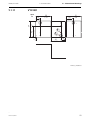
1
VAM I/O units Publication version: VIOen M/A001 User manual Trace back information: Workspace Main version a5 Checked in 2012-10-18 Skribenta version 803 Contents VAM I/O units Contents 1 This document ......................................................................... 5 1.1 1.2 1.3 1.4 2 VAM 3L ............................................................................ 10 VAM 3LX .......................................................................... 12 VAM 10L .......................................................................... 13 VAM 10LD ........................................................................ 14 VAM 12L .......................................................................... 15 VAM 12LD ........................................................................ 17 VAM 4C ............................................................................ 19 VAM 4CD ......................................................................... 20 VAMP 4R ......................................................................... 22 Programming switches ........................................................... 23 4.1 4.2 Switches for arc sensor I/O units ..................................... 23 Switches for current I/O units ........................................... 25 5 Adjusting the overcurrent setting .......................................... 28 6 BI/BO connection .................................................................... 29 7 Connection examples ............................................................. 30 7.1 7.2 7.3 7.4 7.5 7.6 7.7 7.8 8 VAM 3L / VAM 3LX interfaces .......................................... 30 VAM 10L interfaces .......................................................... 31 VAM 10LD interfaces ....................................................... 32 VAM 12L interfaces .......................................................... 33 VAM 12LD ........................................................................ 34 VAM 4C interfaces ........................................................... 35 VAM 4CD interfaces ......................................................... 36 Multiplying relay VAMP 4R ............................................... 37 Technical data .......................................................................... 38 8.1 8.2 3 Purpose ............................................................................ 9 Main properties ................................................................ 9 User interface .......................................................................... 10 3.1 3.2 3.3 3.4 3.5 3.6 3.7 3.8 3.9 4 5 5 6 7 Introduction ............................................................................. 9 2.1 2.2 3 Legal notice ...................................................................... Safety information ............................................................ Related documents .......................................................... Abbreviations and symbols .............................................. Connections ..................................................................... 38 8.1.1 Auxiliary power supply ........................................ 39 8.1.2 Digital inputs (BI/O bus) ...................................... 39 8.1.3 Trip contacts ........................................................ 40 Test and environmental conditions .................................. 41 8.2.1 Environmental conditions .................................... 41 VIOen M/A001 VAM I/O units Contents 8.2.2 8.2.3 9 Casing ................................................................. 41 Package .............................................................. 42 Construction ............................................................................ 43 9.1 Dimensional drawings ...................................................... 43 9.1.1 VAM 3L / 3LX Din rail mounting .......................... 43 9.1.2 VAM 10L Din rail mounting .................................. 44 9.1.3 VAM 10LD Flush mounting ................................. 45 9.1.4 VAM 12L Din rail mounting .................................. 46 9.1.5 VAM 12LD Flush mounting ................................. 47 9.1.6 VAM 4C Din rail mounting ................................... 48 9.1.7 VAM 4CD Flush mounting ................................... 49 9.1.8 VAMP 4R Din rail mounting ................................. 50 9.1.9 VA 1 DA ............................................................... 51 9.1.10 VA 1 EH ............................................................... 51 9.1.11 VYX 001 .............................................................. 52 9.1.12 VYX 002 .............................................................. 53 9.2 I/O unit mounting and wiring ............................................ 54 9.2.1 VAM 3L, VAMP 3LX, VAM 10L, VAM 12L, VAM 4C ........................................................................ 54 9.2.2 VAM 10LD, VAM 12LD, VAM 4CD ...................... 54 9.3 Wiring of the I/O units ...................................................... 55 9.4 Wiring the secondary circuits of the current transformers (VAM 4C / VAM 4CD only) ............................................... 55 9.5 Wiring the trip circuits of the circuit breakers ................... 55 9.6 Wiring between the central unit and the I/O unit .............. 56 9.7 Wiring separate auxiliary supplies ................................... 56 9.8 VAMP 4R ......................................................................... 57 9.9 Wiring multiple central units ............................................. 58 9.10 Arc sensors ...................................................................... 59 10 Order information .................................................................... 63 11 Glossary ................................................................................... 64 VIOen M/A001 4 1 This document 1 This document 1.1 Legal notice VAM I/O units Copyright ©Schneider Electric 2012. All rights reserved. Disclaimer No responsibility is assumed by Schneider Electric for any consequences arising out of the use of this document. This document is not intended as an instruction manual for untrained persons. This document gives instructions on device installation, commissioning and operation. However, the manual cannot cover all conceivable circumstances or include detailed information on all topics. In the event of questions or specific problems, do not take any action without proper authorization. Contact Schneider Electric and request the necessary information. Contact information 35 rue Joseph Monier 92506 Rueil-Malmaison FRANCE Phone: +33 (0) 1 41 29 70 00 Fax: +33 (0) 1 41 29 71 00 www.schneider-electric.com 1.2 5 Safety information • Failure to follow these instructions will result in death or serious injury • Only qualified personnel should install this equipment. Such work should be performed only after reading this entire set of instructions. • Turn off all power supplying this equipment before starting the installation work. • Ensure the protective grounding is connected. • Before performing visual inspections, commissioning, or maintenance on this equipment, disconnect all sources of electric power. VIOen M/A001 VAM I/O units 1.3 1 This document 1.3 Related documents • Assume that all circuits are live until they have been completely de-energised, tested and tagged. Pay particular attention to the design of the power system. Consider all sources of power, including the possibility of backfeeding. • Beware of potential hazards, wear personal protective equipment, carefully inspect the work area for tools and objects that may have been used during commissioning or maintenance. • Neglecting fundamental installation requirements can lead to personal injury as well as damage to electrical equipment or other property. • Handling this equipment requires relevant expertise in the field of protection of electrical networks. Only competent people who have this expertise are allowed to configure and set up this equipment. • Before performing dielectric (Hi-Pot) testing on any equipment in which the IED is installed, disconnect all input and output wires to the IED. High voltage testing can damage electronic components contained in the unit. • Always use a properly rated voltage sensing device to confirm that all power is off. • The successful operation of this equipment depends upon proper handling, installation, and operation. Related documents Table 1.1: Related documents Document Identification*) VAMP Mounting and Commissioning Instructions VARC_MC_xxxx VAMP Arc I/O units user manual VIO_EN_M_xxxx VAMP Arc Flash Protection Testing Manual VARCTEST_EN_M_xxx VAMPSET Setting and Configuration Tool User Manual VVAMPSET_EN_M_xxxx *) xxxx = revision number Download the latest documents and software at www.vamp.fi. VIOen M/A001 6 1.4 Abbreviations and symbols 1.4 1 This document VAM I/O units Abbreviations and symbols Table 1.2: Symbols Symbol Description Indicates a hazardous situation which, if not avoided, will result in death or serious injury. Indicates a hazardous situation which, if not avoided, could result in death or serious injury. Indicates a hazardous situation which, if not avoided, could result in minor or moderate injury. Addresses practices not related to personal injury. Table 1.3: Abbreviations 7 ANSI American National Standards Institute. A standardization organisation. CB Circuit breaker CBFP Circuit breaker failure protection Dead band See hysteresis. DI Digital input DO Digital output, output relay DSR Data set ready. An RS232 signal. Input in front panel port of VAMP relays to disable rear panel local port. DST Daylight saving time. Adjusting the official local time forward by one hour for summer time. DTR Data terminal ready. An RS232 signal. Output and always true (+8 Vdc) in front panel port of VAMP relays. FFT Fast Fourier transform. Algorithm to convert time domain signals to frequency domain or to phasors. Hysteresis I.e. dead band. Used to avoid oscillation when comparing two near by values. IEC International Electrotechnical Commission. An international standardization organisation. IEEE Institute of Electrical and Electronics Engineers IEC-101 Abbreviation for communication protocol defined in standard IEC 60870-5-101 IEC-103 Abbreviation for communication protocol defined in standard IEC 60870-5-103 LAN Local area network. Ethernet based network for computers and relays. Latching Output relays and indication LEDs can be latched, which means that they are not released when the control signal is releasing. Releasing of lathed devices is done with a separate action. NTP Network time protocol for LAN and WWW PT See VT pu Per unit. Depending of the context the per unit refers to any nominal value. For example for overcurrent setting 1 pu = 1xImode. SNTP Simple Network Time Protocol for LAN and WWW TCS Trip circuit supervision THD Total harmonic distortion VIOen M/A001 VAM I/O units VIOen M/A001 1 This document 1.4 Abbreviations and symbols U0sec Voltage at input Uc at zero ohm earth fault. (Used in voltage measurement mode “2LL+Uo”) Ua Voltage input for U12 or UL1 depending of the voltage measurement mode Ub Voltage input for U23 or UL2 depending of the voltage measurement mode Uc Voltage input for U31 or U0 depending of the voltage measurement mode Un Nominal voltage. Rating of VT primary or secondary UTC Coordinated Universal Time (used to be called GMT = Greenwich Mean Time) VT Voltage transformer i.e. potential transformer PT VTpri Nominal primary value of voltage transformer VTsec Nominal secondary value of voltage transformer WWW World wide web (internet) 8 2 Introduction 2 VAM I/O units Introduction This User’s Manual contains a functional description of the VAM I/O units and technical data. 2.1 Purpose The main purpose of the VAM I/O units is to detect arc light or short circuit current and deliver this information (zone information) to the arc protection central unit and the other VAM I/O units. Additionally VAM I/O units can be used for tripping appropriate circuit breakers. 2.2 Main properties Arc flash protection system is a modular system consisting of a central unit, I/O units and arc sensors. Due to its modularity, the system is suitable for a range of arc protection applications, from simple systems with one central unit and one I/O unit to more complex solutions comprising several central units used for selective arc protection. The I/O unit VAM 10L / VAM 10LD, VAM 12L / VAM 12LD serves as link between the system’s point sensors and the central unit. Each I/O unit has connections for ten arc sensors, one portable pin sensor and one trip output. The I/O unit VAM 3L/VAM3LX serves as link between the system’s fibre sensors and the central unit. Each I/O unit has connections for three arc sensors, one pin sensor and one trip output. The I/O unit VAM 4C / VAM 4CD serves as link between the system’s current inputs and the central unit. Each I/O unit has connections for three current transformers and one trip output. The arc sensor VA 1 DA is activated by strong light. The sensor transforms the light information into the current signal, which is forwarded through the I/O unit to the central unit. The arc sensor VA 1 EH also operates on the same principle. The pin sensor VA 1 DP has the same functions as an arc sensor but can be temporarily connected to an I/O unit. The sensor can be fixed to the breast pocket of a technician to improve safety when working with live switchgear. The door mounted VAM I/O units with the letter D in the type designations VAM 10LD, VAM 12LD and VAM 4CD are door mounted versions for the corresponding VAM 10L, VAM 12 L and VAM 4C units. The functionality is exactly the same. 9 VIOen M/A001 VAM I/O units 3 3 User interface User interface Usually, there is no need to touch the front panel during normal operation, since all the necessary information can be read from the central unit display. However, after a new installation or a system expand you will need to program certain functions (zone/address, trip output) in the I/O unit. If you unfasten the terminal blocks during installation, remember to tighten the fixing screws after installation! Also tighten the screws even if you did not unfasten the blocks. 3.1 VAM 3L 12 16 15 14 13 12 11 10 9 8 7 6 5 4 3 2 1 X2 VAM 3L 6 COM 1 COM 2 1 2 SW1 SENSOR BI/O Latch L+I / L OFF 1 2 3 Zone 4 5 Addr. 6 7 ON OK 9 ACT 10 TRIP 11 3 POWER 4 COM 5 ERROR 7 8 SENSOR INPUTS CH1 R1 T1 CH2 R2 T2 CH3 R3 T3 VAM3L 8 Figure 3.1: Arc fibre sensor I/O unit VAM 3L front panel 1. Connection for portable arc sensor (VA 1 DP) 2. Programming switches 3. POWER indicator light, indicates that the supply voltages of each component are in order. 4. COM indicator light, lit when the central units and I/O units are communicating. 5. ERROR indicator light, indicates an internal fault detected by the component’s self-diagnostics. Such faults include faulty arc sensor or changes in the amount of sensors. 6. Connector sockets for the VX001 modular cables 7. LED lights indicating sensor activation VIOen M/A001 10 3.1 VAM 3L 3 User interface VAM I/O units 8. Terminals for three fibre sensors 9. Portable arc sensor VA 1 DP connected and operational 10. Portable arc sensor activated 11. I/O unit trip relay activated 12. Terminal block for external communication and BI/O channels and trip signal 11 VIOen M/A001 VAM I/O units 3.2 3 User interface 3.2 VAM 3LX VAM 3LX 12 16 15 14 13 12 11 10 9 8 7 6 5 4 3 2 1 X2 VAM 3LX 6 COM 1 COM 2 1 2 SW1 BI/O Latch L+I / L OFF 1 2 3 Zone 4 5 Addr. 6 7 ON SENSOR OK 9 ACT 10 TRIP 11 3 POWER 4 COM 5 ERROR 7 8 SENSOR INPUTS CH1 R1 T1 CH2 R2 T2 CH3 R3 T3 CH1 Adj CH2 Adj CH3 Adj 13 8 Min. Max. Min. Max. Min. Max. VAM 3LX Figure 3.2: Arc fibre sensor I/O unit VAM 3LX front panel 1. Connection for portable arc sensor (VA 1 DP) 2. Programming switches 3. POWER indicator light, indicates that the supply voltages of each component are in order. 4. COM indicator light, lit when the central units and I/O units are communicating. 5. ERROR indicator light, indicates an internal fault detected by the component’s self-diagnostics. Such faults include faulty arc sensor or changes in the amount of sensors. 6. Connector sockets for the VX001 modular cables 7. LED lights indicating sensor activation 8. Terminals for three fibre sensors 9. Portable arc sensor VA 1 DP connected and operational 10. Portable arc sensor activated 11. I/O unit trip relay activated 12. Terminal block for external communication and BI/O channels and trip signal 13. Sensitivity adjustments for each fibre sensor channels VIOen M/A001 12 3.3 VAM 10L 3.3 3 User interface VAM I/O units VAM 10L 12 16 15 14 13 12 11 10 9 8 7 6 5 4 3 2 1 X2 VAM 10L 6 COM 1 MOELLER COM 2 1 2 SW1 SENSOR L> ext/int Latch L+I / L OFF 1 2 3 Zone 4 5 Addr. 6 7 ON OK 9 ACT 10 TRIP 11 3 COM 5 ERROR 7 8 1 X1 POWER 4 1 2 2 3 4 SENSOR INPUTS 4 5 6 3 5 6 7 8 9 7 8 9 10 10 11 12 13 14 15 16 17 18 19 20 8 VAM10L Figure 3.3: Arc sensor I/O unit VAM 10L front panel 1. Connection for portable arc sensor (VA 1 DP) 2. Programming switches 3. POWER indicator light, indicates that the supply voltages of each component are in order. 4. COM indicator light, lit when the central unit and I/O units are communicating. 5. ERROR indicator light, indicates an internal fault detected by the component’s self-diagnostics. Such faults include faulty arc sensor or changes in the amount of sensors. 6. Connector sockets for the VX001 modular cables 7. LED lights indicating sensor activation 8. Terminal block for ten arc sensors 9. Portable arc sensor VA 1 DP connected and operational 10. Portable arc sensor activated 11. I/O unit trip relay activated 12. Terminal block for external communication and BI/O channels and trip signal 13 VIOen M/A001 VAM I/O units 3.4 3 User interface 3.4 VAM 10LD VAM 10LD VAM 10LD Arc Protection I/O-UNIT 7 M SENSOR CHANNELS 1 2 3 4 5 6 7 8 9 10 13 ADDRESS NR 10 1. BB FEEDER 7 TRIP 11 2. CB FEEDER 7 3. CC FEEDER 7 5 ERROR 4 COM 3 POWER 4. BB FEEDER 8 5. CB FEEDER 8 6. CC FEEDER 8 7. BB FEEDER 9 FRONT PANEL 8. BB FEEDER 9 9. BB FEEDER 9 10. TIE BREAKER ID 8 20 19 18 17 16 15 14 13 12 11 10 9 8 7 6 5 4 3 2 X1 1 SENSOR INPUTS 2 1 6 COM 1 10 ACT 9 OK O N COM 2 1 2 3 4 5 6 7 8 SENSOR SW1 X2 1 2 3 4 5 6 7 8 9 Zone L/L+I Latch L> Int/ Ext MOELLER BACK PANEL Addr. 10 11 12 13 14 15 16 12 VAM10LD Figure 3.4: Arc sensor I/O unit VAMP 10LD front and back panels 1. Connection for portable arc sensor (VA 1 DP) 2. Programming switches 3. POWER indicator light, indicates that the supply voltages of each component are in order. 4. COM indicator light, lit when the central unit and I/O units are communicating. 5. ERROR indicator light, indicates an internal fault detected by the component’s self-diagnostics. Such faults include faulty arc sensor or changes in the amount of sensors. 6. Connector sockets for the VX001 modular cables 7. LED lights indicating sensor activation 8. Terminal block for ten arc sensors VIOen M/A001 14 3.5 VAM 12L 3 User interface VAM I/O units 9. Portable arc sensor VA 1 DP connected and operational 10. Portable arc sensor activated 11. I/O unit trip relay activated 12. Terminal block for external communication and BI/O channels and trip signal 13. Text pocket for sensor specific labels. 3.5 VAM 12L VAM 12L is primary design for selective feeder trip applications. The unit comprises 3 electromechanical trip normally open contacts and one trip alarm change over contact. The unit has 10 Arc sensor inputs. Tree sensors (of the ten) inputs are dedicated, and are controlling their own trip relay. The unit is ideal for selective trip of cable compartment in case of an ARC fault. VAM 12L can selectively handle 3 feeders. The rest of the sensors can then supervise the busbar and breaker compartments and will operate in the zone selected by the unit address switches. 12 16 15 14 13 12 11 10 9 8 7 6 5 4 3 2 1 X2 VAM 12L 6 COM 1 MOELLER COM 2 1 2 SW1 SENSOR L> ext/int Latch L+I / L OFF 1 2 3 Zone 4 5 Addr. 6 7 ON OK 9 ACT 10 TRIP 3 11 COM 5 ERROR 7 8 1 X1 POWER 4 1 2 2 3 4 SENSOR INPUTS 4 5 6 3 5 6 7 8 9 7 8 9 10 10 11 12 13 14 15 16 17 18 19 20 8 VAM12L Figure 3.5: Arc sensor I/O unit 12L 1. Connection for portable arc sensor (VA 1 DP) 2. Programming switches 3. POWER indicator light, indicates that the supply voltages of each component are in order. 4. COM indicator light, lit when the central unit and I/O units are communicating. 15 VIOen M/A001 VAM I/O units 3 User interface 3.5 VAM 12L 5. ERROR indicator light, indicates an internal fault detected by the component’s self-diagnostics. Such faults include faulty arc sensor or changes in the amount of sensors. 6. Connector sockets for the VX001 modular cables 7. LED lights indicating sensor activation 8. Terminal block for ten arc sensors 9. Portable arc sensor VA 1 DP connected and operational 10. Portable arc sensor activated 11. I/O unit trip relays activated 12. Terminal block for output relay VIOen M/A001 16 3.6 VAM 12LD 3.6 3 User interface VAM I/O units VAM 12LD VAM 12LD Arc Protection I/O-UNIT 7 M SENSOR CHANNELS 1 2 3 4 5 6 7 8 9 10 13 ADDRESS NR 10 1. BB FEEDER 7 TRIP 11 2. CB FEEDER 7 3. CC FEEDER 7 5 ERROR 4 COM 3 POWER 4. BB FEEDER 8 5. CB FEEDER 8 6. CC FEEDER 8 7. BB FEEDER 9 FRONT PANEL 8. BB FEEDER 9 9. BB FEEDER 9 10. TIE BREAKER ID 8 20 19 18 17 16 15 14 13 12 11 10 9 8 7 6 5 4 3 2 X1 1 SENSOR INPUTS 2 1 6 COM 1 10 ACT 9 OK O N COM 2 1 2 3 4 5 6 7 8 SENSOR SW1 X2 1 2 3 4 5 6 7 8 9 Zone L/L+I Latch L> Int/ Ext MOELLER BACK PANEL Addr. 10 11 12 13 14 15 16 12 VAM12LD Figure 3.6: Arc sensor I/O unit VAM 12LD front and back panels 1. Connection for portable arc sensor (VA 1 DP) 2. Programming switches 3. POWER indicator light, indicates that the supply voltages of each component are in order. 4. COM indicator light, lit when the central unit and I/O units are communicating. 5. ERROR indicator light, indicates an internal fault detected by the component’s self-diagnostics. Such faults include faulty arc sensor or changes in the amount of sensors. 6. Connector sockets for the VX001 modular cables 7. LED lights indicating sensor activation 8. Terminal block for ten arc sensors 17 VIOen M/A001 VAM I/O units 3 User interface 3.6 VAM 12LD 9. Portable arc sensor VA 1 DP connected and operational 10. Portable arc sensor activated 11. I/O unit trip relays activated 12. Terminal block for output relays 13. Text pocket for sensor specific labels. VIOen M/A001 18 3.7 VAM 4C 3.7 3 User interface VAM I/O units VAM 4C 12 16 15 14 13 12 11 10 9 8 7 6 5 4 3 2 1 X2 VAM 4C 1 Zone1 Zone2 Zone3 Zone4 Addr. 5 COM 1 COM 2 4.0 POWER 2.0 COM 3 ERROR 4 SW1 OFF 1 2 3 ON 11 TRIP 4 5 6 7 13 8 x In 1.0 6 2 0.5 CURRENT TRANSFORMER L1 L2 0.1 L3 L1/L3 L2/Io X1 SW2 6 0.5 5 0.05 ON x In 1 2 3 4 5 6 7 8 9 10 11 12 7 Latch 1A/5A I> out I> in 1234 8 3 L1,L3 9 1.0 L2/Io 10 VAM4c Figure 3.7: Current I/O unit VAM 4C front panel 1. Programming switches 2. POWER indicator light, indicates the supply voltages of each component are in order. 3. COM indicator light, lit when the central units and I/O units are communicating. 4. ERROR indicator light, indicates an internal fault detected by the component’s self-diagnostics. Such faults include faulty current transformer or phase current unbalance. 5. Connector sockets for the VX001 modular cables 6. LED lights indicating that I> stage has started 7. Terminals for three current transformers 8. Current transformer programming switches 9. Overcurrent setting knob (IL1, IL3), setting range 0.5…6xIN 10. Overcurrent setting knob (IL1, I0), setting range 0.05…5xIN 11. I/O unit trip relay activated 12. Terminal block for external communication and BI/O channels and trip signal 13. Indicator leds for current setting 19 VIOen M/A001 VAM I/O units 3.8 3 User interface 3.8 VAM 4CD VAM 4CD VAM 4CD Arc Protection I/O-UNIT 6 M - - - CURRENT TRANSFORMER - - 1 2 3 14 FEEDER: F06 ADDRESS: 33 ZONE: 1&2 I> PICK-UP: 2 X In OTHER: 4 ERROR 3 COM 2 POWER I> EXT ON TRIP 11 FRONT PANEL 10 9 8 L2/Io L1/L3 SW2 12 11 10 9 8 7 6 5 4 3 2 1 X1 7 4.0 13 SW1 x In 0.5 COM 2 5 Zone4 Zone3 Zone2 Zone1 O N 0.1 1 Addr. COM 1 BACK PANEL MOELLER 1.0 1 2 3 4 5 6 7 8 2.0 12 X2 1 2 3 4 5 6 7 8 9 10 11 12 13 14 15 16 VAM 4CD Figure 3.8: Current I/O unit VAM 4CD front and back panel 1. Programming switches 2. POWER indicator light, indicates the supply voltages of each component are in order. 3. COM indicator light, lit when the central units and I/O units are communicating. 4. ERROR indicator light, indicates an internal fault detected by the component’s self-diagnostics. Such faults include faulty current transformer or phase current unbalance. 5. Connector sockets for the VX001 modular cables 6. LED lights indicating that I> stage has started 7. Terminals for three current transformers 8. Current transformer programming switches VIOen M/A001 20 3.8 VAM 4CD 3 User interface VAM I/O units 9. Overcurrent setting knob (IL1, IL3), setting range 0.5…6xIN 10. Overcurrent setting knob (IL1, I0), setting range 0.05…5xIN 11. I/O unit trip relay activated 12. Terminal block for external communication and BI/O channels and trip signal 13. Indicator leds for current setting 14. Text pocket 21 VIOen M/A001 VAM I/O units 3.9 3 User interface 3.9 VAMP 4R VAMP 4R 12 11 9 8 6 5 4 3 2 1 - + - + X2 VAMP 4R Power TRIP 1 TRIP 2 - + 18...265Vac/dc Trip 1 24Vdc INPUTS Trip 2 OUTPUT TRIP GROUP 2 TRIP GROUP 1 NO NC X1 1 2 NO NC NO NC NO SF ALARM NC NO COM NC 3 4 5 6 7 8 9 10 11 12 13 14 15 16 17 18 19 20 VAMP 4R frontplate Figure 3.9: Multiplying relay VAMP 4R 1. POWER LED, indicates that the external operating voltage of +24 Vdc is connected. 2. Terminals for external operating voltage (+24 Vdc). Can be supplied by central units or I/O units. 3. Terminals for incoming trip signal (e.g. 24 Vdc from VAM I/O unit binary output, 2 groups). Control voltage range is 18 … 265 Vad/dc. 4. Terminals for outgoing trip signals (8 potential-free contacts, 4 normally open, 4 normally closed). VIOen M/A001 22 4 Programming switches 4 VAM I/O units Programming switches Before system implementation, check the positions of the programming switches in accordance with the following basic principles: 4.1 • Each I/O unit connected to the communication bus has its own address (each I/O unit have an unique address). • Set the programming switches before connecting the supply voltage. • If you have to change the switch positions once the supply voltage has been connected, disconnect the supply voltage to the unit in question for the duration of the programming and re-configure the system. • If position of the switch is changed, re-install the system again in the central unit. Switches for arc sensor I/O units The programming switches of the I/O units are used to determine the unit address and trip relay function. The system accommodates up to 16 I/O units. Eight addresses are reserved for each protection zone: • Zone 1 addresses 0…7 • Zone 2 addresses 8…15 • Zone 3 addresses 16…23 • Zone 4 addresses 24…31 The programming switches have different weight factors. To create an address for the I/O unit, turn switches with different values to the ON position and calculate the sum of their weight factors. The following table shows the weight factors of each programming switch. Table 4.1: Programming switch weight factors, *) VAM 3L and VAM 3LX, VAM 10L / VAM 10LD, VAM 12L / VAM 12LD only Switch No. Weight factor 8 1 7 2 6 4 5 8 4 *) 16 Note the position of the VAM 12LD, VAM 10LD and VAM 4CD dip switches. 23 VIOen M/A001 VAM I/O units 4 Programming switches 4.1 Switches for arc sensor I/O units VAM 12LD / VAM 10LD VAM 3L / VAM 3LX SW1 SENSOR SW1 BI/O Latch L+I / L OFF 1 2 3 Zone 4 5 Addr. 6 7 ON ACT SENSOR ON 8 7 6 5 4 3 2 1 OK OK OFF Addr. Zone L / L+I Latch L> ext/int ACT TRIP 8 M VAM 10L / VAM 12L M SW1 L> ext/int Latch L+I / L OFF 1 2 3 Zone 4 5 Addr. 6 7 ON SENSOR OK ACT TRIP 8 VAM3L/VAM3LX, VAM10L/VAM10LD, VAM12L/VAM12LD dips Figure 4.1: Programming switches for VAM 3L, VAM 3LX, VAM 10L, VAM 10LD, VAM 12L and VAM 12LD VAM 3L / VAM 3LX, VAM 10L / VAM 10LD Switch 1 determines which light activation activates the arc stage. When the switch position is ON, the arc stage only activates on the light information provided by the unit's own sensors. In OFF position the arc stage activates on the light information received from any unit in the same protection zone. Switch 2 determines the trip relay latch. When the switch is in ON position the trip relay remains engaged after the arc trip until the fault is acknowledged at the central unit’s panel. In the OFF position the trip relay follows the arc fault. Switch 3 determines the arc trip criteria. When the switch is in ON position the trip is based on light information only; in OFF position both fault currents exceeding the current limit and light information are required. VIOen M/A001 24 4.2 Switches for current I/O units 4 Programming switches VAM I/O units VAM 12L / VAM 12LD When the L>ext/int DIP switch is in “L>int” position, the output relays are only activated by dedicated sensors. SENSOR 1 activates T1. SENSOR 2 activates T2. SENSOR 3 activates T3. SENSORS 4 to 10 are normally sending light information to system according to zone setting. If the switch is in “L>ext” position, all output relays are also controlled by the selected zone information. This activation source can be any sensor channel 4 to 10 or from an external I/O unit configured to the same zone. 4.2 Switches for current I/O units The address range for current I/O units is (32),33…46. Do not use address 32, because in this case the current I/O unit operates in CENTRAL UNIT mode and the actual central unit must be set to SUB-UNIT mode. To determine the address of a current I/O unit, add the sum of the weight factors to 32 (for example, programming switch values total 7, address of the current I/O unit 32 + 7 = 39). Do not use 32 as the unit address if system have central unit. Other programming switches have different functions in different units, as described below. VAM 4C / VAM 4CD VAM 4C SW1 OFF 1 SW2 4 11 12 5 Addr. 0.5 5 0.05 x In 1234 TRIP 3 6 ON ON 2 3 L1,L3 Latch 1A/5A I> out I> in Zone1 Zone2 Zone3 Zone4 1.0 L2/Io 6 7 8 VAM4C_dips VAM 4CD SW1 6 5 4 3 2 1 OFF SW2 Addr. 6 0.5 5 0.05 ON x In Zone4 Zone3 Zone2 Zone1 1234 11 12 Latch 1A/5A I> out I> in ON 8 7 3 L1,L3 M 1.0 L2/Io VAM4CD_dips 25 Figure 4.2: Programming switches of VAM 4C / VAM 4CD VIOen M/A001 VAM I/O units 4 Programming switches 4.2 Switches for current I/O units Table 4.2: VAM4C dipswitches weight factors SW NO: Weight factor 8 1 7 2 6 4 5 8 SW1 switch settings VIOen M/A001 Switch Definition Description 1 Zone 1 System operating zone 1 (light information) 2 Zone 2 System operating zone 2 (light information) 3 Zone 3 System operating zone 3 (light information) 4 Zone 4 System operating zone 4 (light information) 5 Addr Address weighting coefficient 8 6 Addr Address weighting coefficient 4 7 Addr Address weighting coefficient 2 8 Addr Address weighting coefficient 1 26 4.2 Switches for current I/O units 4 Programming switches VAM I/O units SW2 switch settings Switch Definition Description 1 Latch Position ”0” (switch down): trip relay is only operational while the protection is activated Position ”1” (switch up): trip relay changes to latching status after trip 2 1A / 5A * Position ”0” (switch down): rated secondary current of the current transformer is 1 A Position ”1” (switch up): rated secondary current of the current transformer is 5 A 3 I> out Position ”0” (switch down): unit does not transmit the current criteria to other units Position ”1” (switch up): unit transmits the current criteria to other units 4 I> in Position ”0” (switch down): unit does not receive the current criteria from other units Position ”1” (switch up): unit receives the current criteria from other units *) As in CT 27 VIOen M/A001 VAM I/O units 5 5 Adjusting the overcurrent setting Adjusting the overcurrent setting The principles for changing the current setting in VAM 4C units are the same as for the central unit. You can see the estimated current setting from the led bar on the right side of the unit. The most accurate way of setting the current limit for the unit is as follows: • Turn the potentiometer to the maximum value. • Feed a test current corresponding to the required setting using a testing device. • Lower the setting until the current activation indicator led of the I/O unit and the I>ext indicator led in the central unit are lit. 16 15 14 13 12 11 10 9 8 7 6 5 4 3 2 1 X2 VAM 4C COM 1 COM 2 4.0 POWER SW1 Zone1 Zone2 Zone3 Zone4 TRIP Addr. 2.0 x In 1.0 COM ERROR 0.5 CURRENT TRANSFORMER L1 L2 X1 0.1 L3 L1/L3 L2/Io VAM4c conn Figure 5.1: Adjusting the current setting in VAM 4C VIOen M/A001 28 6 BI/BO connection 6 VAM I/O units BI/BO connection Each I/O unit also has a BI/O bus. The light I/O units (VAM 3L / VAM 3LX, VAM 10L / VAM 10LD, VAM 12L / VAM 12LD) can transmit trip signal to the central unit or current I/O unit. The current I/O unit (VAM 4C / VAM 4CD) can receive the light information and send the current information either to other I/O units or the multiplying relay. The DI/DO on the VAM units are fast BI/BO signals. The following DI and DO connections are included in the standard delivery of VAM 3L / VAM 3LX and VAM 10L units: DI X2-8 Zone shift 1(2, 2(1, 3(4, 4(3 GND X2-7 Trip out X2-10 Trip signal, 24 V dc GND X2-9 Trip signal earth The following DI and DO connections are included in the standard delivery of VAM 4C units: 29 L>in X2-8 Light input, 24-48 V dc GND X2-7 Light input earth Trip out X2-10 Trip signal GND GND Trip signal earth VIOen M/A001 VAM I/O units 7 Connection examples 7 Connection examples 7.1 VAM 3L / VAM 3LX interfaces 16 15 14 13 12 11 10 9 8 7 6 5 4 3 2 1 X2 VAM 3L / 3LX COM 1 COM 2 SW1 SENSOR BI/O Latch L+I / L OK POWER ACT COM Zone TRIP ERROR Addr. SENSOR INPUTS CH1 R1 T1 CH2 R2 T2 CH3 R3 T3 VAM3L/VAM 3LX conn X1-R1: Fiber receiver connection X1-T1: Fiber transmitter connection X1-R2: Fiber receiver connection X1-T2: Fiber transmitter connection X1-R3: Fiber receiver connection X1-T3: Fiber transmitter connection X2-1: +24V supply from master unit or external power supply X2-2: GND X2-3: CAN-L X2-4: CAN-H X2-5: Serial B X2-6: Serial A X2-7: DI GND Zone change X2-8 DI (24-48Vdc) (1 -> 2; 2 -> 1; Channel 1 Channel 2 Channel 3 Zone information (L>, I>) = COM1, COM2 master slave com 3 -> 4; 4 -> 3) X2-9: DO GND X2-10: DO +24Vdc X2-11: + Temp sensor X2-12: - Temp sensor Trip signal (DI&DO) Not in use X2-13: X2-14: VIOen M/A001 X2-15: Trip relay (NO) X2-16: Trip relay (NO) 30 7.2 VAM 10L interfaces 7.2 7 Connection examples VAM I/O units VAM 10L interfaces 16 15 14 13 12 11 10 9 8 7 6 5 4 3 2 1 X2 VAM 10L COM 1 MOELLER COM 2 SW1 SENSOR L> ext/int Latch L+I / L OK POWER ACT COM Zone TRIP ERROR Addr. 1 X1 1 2 2 3 4 3 5 6 4 7 8 SENSOR INPUTS 5 6 9 7 8 9 10 10 11 12 13 14 15 16 17 18 19 20 VAM10L conn X1-1,2: arc sensor channel 1 X1-3,4: arc sensor channel 2 X1-5,6: arc sensor channel 3 X1-7,8: arc sensor channel 4 X1-9,10: arc sensor channel 5 X1-11,12: arc sensor channel 6 X1-13,14: arc sensor channel 7 X1-15,16: arc sensor channel 8 X1-17,18: arc sensor channel 9 X1-19,20: arc sensor channel 10 X2-1: +24V supply from masterunit or external power supply X2-2: GND X2-3: CAN-L X2-4: CAN-H X2-5: Serial B X2-6: Serial A X2-7: DI GND Zone change X2-8: DI (24-48Vdc) (1 -> 2; 2 ->1; Zone information (L>, I>) =COM1, COM2 Master slave com 3 -> 4; 4 -> 3) X2-9: DO GND X2-10: DO +24Vdc X2-11: + Temp sensor X2-12: - Temp sensor Trip signal Not in use X2-13: X2-14: 31 X2-15: Trip relay (NO) X2-16: Trip relay (NO) VIOen M/A001 VAM I/O units 7.3 7 Connection examples 7.3 VAM 10LD interfaces VAM 10LD interfaces 20 19 18 17 16 15 14 13 12 11 10 9 8 7 6 5 4 3 2 X1 1 SENSOR INPUTS ACT COM 1 O N COM 2 OK 1 2 3 4 5 6 7 8 SW1 SENSOR Addr. Zone L/L+I Latch L> Int/ Ext MOELLER X2 1 2 3 4 5 6 7 8 9 10 11 12 13 14 15 16 VAM10LD conn X1-1,2: arc sensor channel 1 X1-3,4: arc sensor channel 2 X1-5,6: arc sensor channel 3 X1-7,8: arc sensor channel 4 X1-9,10: arc sensor channel 5 X1-11,12: arc sensor channel 6 X1-13,14: arc sensor channel 7 X1-15,16: arc sensor channel 8 X1-17,18: arc sensor channel 9 X1-19,20: arc sensor channel 10 X2-1: +24V supply from masterunit or external power supply X2-2: GND X2-3: CAN-L X2-4: CAN-H X2-5: Serial B X2-6: Serial A X2-7: DI GND Zone change X2-8: DI (24-48Vdc) (1 -> 2; 2 ->1; Zone information (L>, I>) =COM1, COM2 Master slave com 3 -> 4; 4 -> 3) X2-9: DO GND X2-10: DO +24Vdc X2-11: + Temp sensor X2-12: - Temp sensor Trip signal Not in use X2-13: X2-14: VIOen M/A001 X2-15: Trip relay (NO) X2-16: Trip relay (NO) 32 7.4 VAM 12L interfaces 7.4 7 Connection examples VAM I/O units VAM 12L interfaces 16 15 14 13 12 11 10 9 8 7 6 5 4 3 2 1 X2 VAM 12L COM 1 MOELLER COM 2 SW1 SENSOR L> ext/int Latch L+I / L OFF 1 2 3 Zone 4 5 Addr. 6 7 ON OK POWER ACT COM TRIP ERROR 8 1 X1 1 2 2 3 4 3 5 6 4 7 8 SENSOR INPUTS 5 6 9 7 8 9 10 10 11 12 13 14 15 16 17 18 19 20 VAM12L conn X1-1,2: arc sensor channel 1 X1-3,4: arc sensor channel 2 X1-5,6: arc sensor channel 3 X1-7,8: arc sensor channel 4 X1-9,10: arc sensor channel 5 X1-11,12: arc sensor channel 6 X1-13,14: arc sensor channel 7 X1-15,16: arc sensor channel 8 X1-17,18: arc sensor channel 9 X1-19,20: arc sensor channel 10 X2-1: +24v supply from masterunit or external power supply X2-2: GND X2-3: X2-4: COM X2-5: NO X2-6: NC Alarm X2-7: X2-8: Trip relay 3 (NO) X2-9: Trip relay 3 (NO) X2-10: X2-11: Trip relay 2 (NO) X2-12: Trip relay 2 (NO) X2-13: X2-14: 33 X2-15: Trip relay 1 (NO) X2-16: Trip relay 1 (NO) VIOen M/A001 VAM I/O units 7.5 7 Connection examples 7.5 VAM 12LD VAM 12LD 20 19 18 17 16 15 14 13 12 11 10 9 8 7 6 5 4 3 2 X1 1 SENSOR INPUTS ACT COM 1 O N COM 2 OK 1 2 3 4 5 6 7 8 SW1 SENSOR Addr. Zone L/L+I Latch L> Int/ Ext MOELLER X2 1 2 3 4 5 6 7 8 9 10 11 12 13 14 15 16 VAM12LD conn X1-1,2: arc sensor channel 1 X1-3,4: arc sensor channel 2 X1-5,6: arc sensor channel 3 X1-7,8: arc sensor channel 4 X1-9,10: arc sensor channel 5 X1-11,12: arc sensor channel 6 X1-13,14: arc sensor channel 7 X1-15,16: arc sensor channel 8 X1-17,18: arc sensor channel 9 X1-19,20: arc sensor channel 10 X2-1: +24v supply from masterunit or external power supply X2-2: GND X2-3: X2-4: COM X2-5: NO X2-6: NC Alarm X2-7: X2-8: Trip relay 3 (NO) X2-9: Trip relay 3 (NO) X2-10: X2-11: Trip relay 2 (NO) X2-12: Trip relay 2 (NO) X2-13: X2-14: VIOen M/A001 X2-15: Trip relay 1 (NO) X2-16: Trip relay 1 (NO) 34 7.6 VAM 4C interfaces 7.6 7 Connection examples VAM I/O units VAM 4C interfaces 16 15 14 13 12 11 10 9 8 7 6 5 4 3 2 1 X2 VAM 4C COM 1 COM 2 4.0 POWER SW1 Zone1 Zone2 Zone3 Zone4 TRIP Addr. 2.0 x In 1.0 COM ERROR 0.5 CURRENT TRANSFORMER L1 L2 0.1 L3 L1/L3 L2/Io X1 VAM4c conn X1-1,3: Current input IL1 X1-5,7: Current input IL2 / Io X1-9,11. Current input IL3 X2-1: +24V supply from master unit or external power supply X2-2: GND X2-3: CAN-L X2-4: CAN-H X2-5: Serial B X2-6: Serial A X2-7: DI GND X2-8: DI (24-48Vdc) X2-9: DO GND X2-10: DO +24Vdc Zone information (L>, I>) = COM1, COM2 master slave com L> TRIP X2-11: X2-12: X2-13: X2-14: 35 X2-15: Trip relay (NO) X2-16: Trip relay (NO) VIOen M/A001 VAM I/O units 7.7 7 Connection examples 7.7 VAM 4CD interfaces VAM 4CD interfaces L2/Io L1/L3 SW2 12 11 10 9 8 7 6 5 4 3 2 1 X1 4.0 SW1 1.0 1 2 3 4 5 6 7 8 2.0 x In 0.5 O N 0.1 COM 2 Addr. Zone4 Zone3 Zone2 Zone1 COM 1 MOELLER X2 1 2 3 4 5 6 7 8 9 10 11 12 13 14 15 16 VAM4CD conn X1-1,3: Current input IL1 X1-5,7: Current input IL2 / Io X1-9,11. Current input IL3 X2-1: +24V supply from master unit or external power supply X2-2: GND X2-3: CAN-L X2-4: CAN-H X2-5: Serial B X2-6: Serial A X2-7: DI GND X2-8: DI (24-48Vdc) X2-9: DO GND X2-10: DO +24Vdc Zone information (L>, I>) = COM1, COM2 master slave com L> TRIP X2-11: X2-12: X2-13: X2-14: VIOen M/A001 X2-15: Trip relay (NO) X2-16: Trip relay (NO) 36 7.8 Multiplying relay VAMP 4R 7.8 7 Connection examples VAM I/O units Multiplying relay VAMP 4R 12 11 9 8 6 5 4 3 2 1 - + - + X2 VAMP 4R TRIP 1 Power TRIP 2 - + 18...265Vac/dc Trip 1 24Vdc INPUTS Trip 2 OUTPUT TRIP GROUP 2 TRIP GROUP 1 NO NC X1 1 2 NO NC NO NC NO SF ALARM NC NO COM NC 3 4 5 6 7 8 9 10 11 12 13 14 15 16 17 18 19 20 VAMP 4R frontplate X1-1,2: Trip relay (NO), Trip group 1. X1-3,4: Trip relay (NC), Trip group 1. X1-5,6: Trip relay (NO), Trip group 1. X1-7,8: Trip relay (NC), Trip group 1. X1-9,10: Trip relay (NO), Trip group 2. X1-11,12: Trip relay (NC), Trip group 2. X1-13,14: Trip relay (NO), Trip group 2. X1-15,16: Trip relay (NC), Trip group 2. X1-17: X1-18: NO X1-19: COM X1-20: NC X2-1: Aux voltage supply +24Vdc X2-2: GND X2-3: Aux voltage supply +24Vdc X2-4: GND X2-5: Aux voltage supply +24Vdc X2-6: GND SF Alarm relay X2-7: X2-8: TRIP 2. Input 18...265Vac/dc X2-9: TRIP 2. Input 18...265Vac/dc Trip group 2. X2-10: 37 X2-11: TRIP 1. Input 18...265Vac/dc X2-12: TRIP 1. Input 18...265Vac/dc Trip group 1. VIOen M/A001 VAM I/O units 8 Technical data 8 Technical data 8.1 Connections VAM 3L Sensor connections 3 fibre loop sensors (type ARC-SLx) 1 portable arc sensor (type VA 1 DP) VAM 3LX Sensor connections 3 fibre loop sensors (type ARC-SLx) - sensitivity adjust range compared to 3L 0,5 (max) … 1,5 (min) 1 portable arc sensor (type VA 1 DP) VAM 10L, VAM 10LD, VAM 12L, VAM 12LD Sensor connections 10 arc sensors (type VA 1 DA or VA 1 EH) 1 portable arc sensor (type VA 1 DP) Terminal: Maximum cross-section area of wire - Phoenix MVSTBW or similar 2.5 mm2 (13-14 AWG) VAM 4C, VAM 4CD Rated current L1 / L3 1 or 5 A (optional) 50/60Hz - current measuring zone 0 … 6 A (0 … 6*IN [IN =1A]); - thermal withstand capability 0 … 30 A (0 … 6* IN [IN =5A]) - power consumption 300 A (for 1s) 100 A (for 10s) 20 A (continuous) <0.3 VA Rated current L2 / I0 1 or 5 A (optional) 50/60Hz - current measuring zone 0 … 6 A (0 … 6*IN [IN =1A]); - thermal withstand capability 0 … 30 A (0 … 6* IN [IN =5A]) - power consumption 300 A (for 1s) 100 A (for 10s) 20 A (continuous) <0.3 VA VIOen M/A001 Terminal: Maximum cross-section area of wire - single or multi-strand wire 4 mm2 (10-12 AWG) 38 8.1 Connections 8.1.1 8 Technical data VAM I/O units Auxiliary power supply VAM 3L, VAM 3LX, VAM 10L, VAM 10LD, VAM 12L, VAM 12LD, VAM 4C, VAM 4CD Rated voltage UAUX 24 V dc Power consumption < 1 W (in normal mode) < 1.5 W (output relays activated) Terminal: Maximum cross-section area of wire - Phoenix MVSTBW or similar 2.5 mm2 (13-14 AWG) ( RJ 45 when supply from central unit) VAR 4CE Rated voltage UAUX 24 V dc Power consumption < 0.5 W (in normal mode) < 4.5 W (output relays activated) Terminal: Maximum cross-section area of wire - fixed terminal 2.5 mm2 (13-14 AWG) VAMP 4R Rated voltage UAUX 24 V dc Current consumption 20 mA stby - one relay group activated 80 mA - both relay groups activated 180 mA VA 1 DA, VA 1 EH, VA 1 DP Rated voltage UAUX 12 V dc (from I/O unit) Power consumption < 35 mW (in normal mode) < 450 mW (activated) 8.1.2 Digital inputs (BI/O bus) No digital inputs available in VAM 12L and VAM 12LD VAM 3L, VAM 3LX, VAM 10L, VAM 10LD Number of inputs 1 pcs I> in 1 arc fault trip out Internal operating voltage 24…48 V dc (BIO in) 24 V dc (BIO out) 39 Load capacity (max.) 5 mA Terminal: Maximum cross-section area of wire - Phoenix MVSTBW or similar 2.5 mm2 (13-14 AWG) VIOen M/A001 VAM I/O units 8 Technical data 8.1 Connections VAM 4C Number of inputs 1 pcs L> in 1 pcs I> out Internal operating voltage 24…48 V dc (BIO in) 24 V dc (BIO out) Load capacity (max.) 5 mA Terminal: Maximum cross-section area of wire - Phoenix MVSTBW or similar 2.5 mm2 (13-14 AWG) VAMP 4R 8.1.3 Operating voltage 18…265 V ac/dc Current consumption 2 mA Trip contacts VAM 3L, VAM 3LX, VAM 10L, VAM 10LD, VAM 12L, VAM 12LD, VAM 4C, VAM 4CD Number of contacts 1 closing contact (relay T1) for VAM 10L, VAM 10LD, VAM 3L, VAM 3LX, VAM 4C, VAM 4CD Number of contacts 3 closing contacts (relay T1) for VAM 12L, VAM 12LD Rated voltage 250 V ac/dc Continuous withstand capacity 5A Make and carry for 0.5s 30 A Make and carry for 3s 15 A Breaking capacity, dc(L/R=40 ms) VIOen M/A001 At 48 V dc: 1A At 110 V dc: 0.44 A At 220 V dc: 0.22 A Relay material AgNi 90/10 Terminal: Maximum cross-section area of wire - Phoenix MVSTBW or similar 2.5 mm2 (13-14 AWG) 40 8.2 Test and environmental conditions 8 Technical data VAM I/O units VAMP 4R 4N/O / 4N/C rated voltage 250V ac/dc Continuous withstand capacity 5A Make and carry for 0.5s 30A Make and carry for 3s 15A N/O breaking capacity dc (L/R=40ms) At 48 V dc 1A At 110 V dc 0.44A At 220 V dc 0.22A Contact material AgNi 90/10 Terminal: Maximum cross-section area of wire - Phoenix MVSTBW or similar 2.5 mm2 (13-14 AWG) 8.2 Test and environmental conditions 8.2.1 Environmental conditions Operating temperature range -10 … +55°C Transport and storage temperature range -40 … +70°C - VAM I/O units -40 … +85°C - ARC SLm, VA 1 xx sensors Relative air humidity <75% (1 year, average) <90% (30 days per year, condensation not allowed) Operation altitude 8.2.2 2000 m Casing VAM 3L, VAM 3LX, VAM 10L, VAM 4C, VAMP 4R 41 Housing class (IEC 60529) IP21 Dimensions (WxHxD) 157x92x25 mm Material 1mm steel plate Weight 0.52 kg Colour code RAL 7032 (housing) / RAL 70035 (back plate) VIOen M/A001 VAM I/O units 8 Technical data 8.2 Test and environmental conditions VAM 10LD, VAM 12LD, VAM 4CD Door mounted (IEC 60529) IP64 Dimensions (WxHxD) 185x120x25 mm Material 1mm steel plate Weight 0.60 kg Colour code RAL 7032 (housing) / RAL 70035 (back plate) VA 1 DA, VA 1 EH, VA 1 DP Housing class (IEC 60529) IP21 Dimensions (WxHxD) 25x55x14 mm (VA 1 DA) Φ11x62 mm (VA 1 EH) Φ40x7 mm (VA 1 DP) Material Plastic Weight 0.01 kg Cable length 6 m or 20 m (VA 1 DP 5 m) 8.2.3 Package Dimensions (WxHxD) VAMP 4R: 157 x 92 x 25 mm VAM 10L: 157 x 92 x 25 mm VAM 3L: 157 x 92 x 25 mm VAM 3LX: 157 x 92 x 25 mm VAM 4C: 157 x 92 x 25 mm Weight (unit, box and user instructions) VAMP 4R: 0.62 kg VAM 10L: 0.62 kg VAM 3L: 0.62 kg VAM 3LX: 0.62 kg VAM 4C: 0.62 kg VIOen M/A001 42 9 Construction VAM I/O units 9 Construction 9.1 Dimensional drawings 9.1.1 VAM 3L / 3LX Din rail mounting mm in LX VAM 3L / 3 92 3.62 112 4.41 157 6.18 VAM 3L / 3 25 0.98 LX T max. 0.5...0.6Nm 4.4...5.3 lb.in X L / 3L VAM 3 VAM 3L / 3 LX EN 50022 35 mm 1.38 in 43 VIOen M/A001 VAM I/O units 9.1.2 9 Construction 9.1 Dimensional drawings VAM 10L Din rail mounting mm in 157 6.18 112 4.41 92 3.62 25 0.98 T max. 0.5...0.6Nm 4.4...5.3 lb.in EN 50022 35 mm 1.38 in VIOen M/A001 44 9.1 Dimensional drawings 9.1.3 9 Construction VAM I/O units VAM 10LD Flush mounting mm in 105 4.13 T max. 0.5...0.6Nm 4.4...5.3 lb.in 92 3.62 ø4.5 0.18 1.0 0.0- 3.0 40.1 170 6.69 157 6.18 2 min. 2.5mm2 27 . 6 1.0 9 120 4.72 90 3.5 4 185 7.28 45 VIOen M/A001 VAM I/O units 9.1.4 9 Construction 9.1 Dimensional drawings VAM 12L Din rail mounting mm in 157 6.18 112 4.41 92 3.62 25 0.98 T max. 0.5...0.6Nm 4.4...5.3 lb.in EN 50022 35 mm 1.38 in VIOen M/A001 46 9.1 Dimensional drawings 9.1.5 9 Construction VAM I/O units VAM 12LD Flush mounting mm in 105 4.13 T max. 0.5...0.6Nm 4.4...5.3 lb.in 92 3.62 ø4.5 0.18 P 12 1.0 0.0- 3.0 40.1 170 6.69 VAM 1D 157 6.18 2 min. 2.5mm2 27 . 6 1.0 9 P 12 VAM 1D P 12 VAM 120 4.72 1D 90 3.5 4 185 7.28 47 VIOen M/A001 VAM I/O units 9.1.6 9 Construction 9.1 Dimensional drawings VAM 4C Din rail mounting mm in 92 3.62 112 4.41 157 6.18 25 0.98 T max. 0.5...0.6Nm 4.4...5.3 lb.in EN 50022 35 mm 1.38 in VIOen M/A001 48 9.1 Dimensional drawings 9.1.7 9 Construction VAM I/O units VAM 4CD Flush mounting mm in 2 105 4.13 T max. 0.5...0.6Nm 4.4...5.3 lb.in 1 92 3.62 ø4.5 0.18 DIP ON 1 2 1.0 0.0- 3.0 40.1 4CD -UNIT tion I/O VAM Protec 170 6.69 --- RMER Arc 157 6.18 3 4 RENT TRAN SFO ---CUR L3 L2 L1 R ERRO COM ER POW TRIP 2 min. 2.5mm2 3 27. 6 1.0 9 DIP ON 1 2 4CD -UNIT tion I/O VAM Protec RMER Arc RENT TRAN ---CUR TRIP DIP --- SFO L3 L2 L1 3 4 ON 1 2 R ERRO COM ER POW 90 3.5 4 4CD -UNIT tion I/O VAM Protec 3 4 --- RMER TR RENT Arc ANSFO ---CUR L3 L2 L1 R ERRO COM ER POW 120 4.72 TRIP 185 7.28 49 VIOen M/A001 VAM I/O units 9.1.8 9 Construction 9.1 Dimensional drawings VAMP 4R Din rail mounting mm in 157 6.18 112 4.41 92 3.62 25 0.98 T max. 0.5...0.6Nm 4.4...5.3 lb.in EN 50022 35 mm 1.38 in VIOen M/A001 50 9.1 Dimensional drawings 9.1.9 9 Construction VAM I/O units VA 1 DA mm in 22.2 0.83 20 0.79 10 0.39 14 0.55 46.4 1.83 25 0.98 8 0.31 4.2 0.17 VA1DA_mittakuva 9.1.10 VA 1 EH 62 2.44 11 0.43 mm in VA1EH_mittakuva 51 VIOen M/A001 VAM I/O units 9.1.11 9 Construction 9.1 Dimensional drawings VYX 001 15 0.59 50 1.97 25 0.98 51 2.0 7 0.28 5 2. .1 0 42 1.65 59 2.32 mm in 10 0.3 9 50 1.97 15 0.59 VYX001_mittakuva VIOen M/A001 52 9.1 Dimensional drawings 9.1.12 9 Construction VAM I/O units VYX 002 1 0. 0 39 mm in 59 2.32 15 0.59 15 0.59 3 0.1 2 30 1.18 30 1.18 VYX002 53 VIOen M/A001 VAM I/O units 9.2 9 Construction 9.2 I/O unit mounting and wiring I/O unit mounting and wiring Read this User's Manual carefully before undertaking any installation or wiring work. Safety instructions Always observe the national electrical safety regulations when working under live conditions. The unit manufacturer is not liable for damage due to incorrect working methods or failure to observe safety instructions. The correct handling of the unit under all mounting and operating conditions forms the foundation for its safe use. Any separately marked notes and warnings must be observed. The wiring work must be performed according to national standards and any requirements specified by the customer. Do not connect the auxiliary supply voltage until the installation has been completed. Before installation Before installation, make sure the environmental conditions comply with the requirements specified in Chapter 7. The unit contains components liable to damage if exposed to an electrostatic discharge (ESD). Do not open the unit unless you have taken appropriate protective measures against ESD. The manufacturer cannot guarantee operational safety in environments that do not satisfy the specified environmental conditions. 9.2.1 VAM 3L, VAMP 3LX, VAM 10L, VAM 12L, VAM 4C The units are designed for mounting on a DIN rail. Mount the units on the rail in such a way that the indicator lights on the front panel are visible and the sensor wiring can be made as easily as possible. 9.2.2 VAM 10LD, VAM 12LD, VAM 4CD The units are designed for mounting on a door. Hence all indicators are clearly visible in normal operation. VIOen M/A001 54 9.3 Wiring of the I/O units 9.3 9 Construction VAM I/O units Wiring of the I/O units The I/O units can be connected to the following: 9.4 • secondary circuits of the current transformers of the switchgear (VAM 4C only) • the trip circuits of the circuit breakers • external auxiliary supply circuits • connections to the central unit or other I/O units (data communication and auxiliary supply) • connections to other central units or protection relays (DI or DO bus) Wiring the secondary circuits of the current transformers (VAM 4C / VAM 4CD only) Connect the secondary circuits of the current transformers to the following screw connectors: • X1-1, X1-3 (L1) • X1-5, X1-7 (L2/I0) • X1-9, X1-11 (L3) The arc protection system can also be single or two-phase connected. Three-phase connection is nevertheless recommended for optimal operating speed. The current measuring channels L1 and L3 must be used in connection with two-phase current measuring. Single-phase current or earth-fault current must always be connected to the current measuring channel L2/I0; otherwise, an unbalance error will occur. The specified operating time of 7ms can only be guaranteed for three-phase current measurement. 9.5 Wiring the trip circuits of the circuit breakers Connect the circuit breaker’s trip circuit to the following terminals: TRIP1: X2-15, X2-16 (fast) In the event of an arc fault, the output contact will close at 7 ms when three-phase current measurement is used. 55 VIOen M/A001 VAM I/O units 9 Construction 9.6 Wiring between the central unit and the I/O unit The output trip relay of the light I/O units (VAM 10L and VAM 3 L) operates during faults in its own zone. In the current I/O unit (VAM 4 C), select the protection zone controlling the I/O unit using the programming switches. If several trips are required, the multiplying relay VAMP 4R can be used. 9.6 Wiring between the central unit and the I/O unit Connect the central unit to the I/O units with a modular cable of type VX001. The modular cable carries all information between the central unit and I/O units, including data in serial form, arc fault messages and operating supply to the I/O units. • Connect the VX001 cable to the arc I/O COM interface of the central units. • Connect the cable to COM1 or COM2 on the first I/O unit. • Route the cable from COM1 or COM2 on the first I/O unit to COM1 or COM2 in the next unit, etc. All the COM1 and COM2 interfaces are identical, i.e. the cable can always be connected to either interface. The maximum total length of the modular cable, taking into account all the I/O units connected to the central unit, is 100 m. Use only star connection for I/O units. Closed loop will cause communication errors. 9.7 Wiring separate auxiliary supplies When routing modular cables over long distances or when the system contains several I/O units, you should preferably use a separate auxiliary supply parallel with the modular cable. Connect the auxiliary supply to the 24 V terminals of the central unit to the 24 V terminals in the I/O units. Alternatively, you can also use a separate external voltage supply 3P004. Pay particular attention to the polarity of the cable connections. VIOen M/A001 56 9.8 VAMP 4R 9.8 9 Construction VAM I/O units VAMP 4R + 24 Vdc 18...265 V ac/dc - + - +-+ 12 11 9 8 6 5 4 3 2 1 :X2 VAMP 4R Group 1 X1: 1 2 3 4 5 6 7 8 Group 2 9 10 11 12 13 14 15 16 Self supervision alarm 19 20 18 VAMP4R Block diagram Figure 9.1: VAMP 4R block diagram The multiplying relay VAMP 4R can be used when additional trip outputs are needed. VAMP 4R comprises 4 N/O contacts and 4 N/C contacts. They are divided into two separate groups which can be independently controlled by e.g. the binary output of the I/O units or the central unit. • Attach the VAMP 4R unit to a DIN rail. • Connect the auxiliary voltage ( +24V ) to terminal X2-1 (+) and X2-2 (-). Terminals X2-3 and X2-5 are parallel inputs to X2-1(+). Terminals X2-4 and X2-6 are parallel inputs to X2-2(1). The auxiliary voltage ( +24V ) can be supplied from the central unit or nearest slave ( X2-1 (+), X2-2 (-)). • Connect the required signal (18-265 V ad/dc) to the trip control inputs. • Input “TRIP 1” ( X2-11, X2-12 ) is controlling the trip group 1. Input “TRIP 2” ( X2-8, X2-9 ) is controlling the trip group 2. • There are 2xN/C + 2xN/O contacts per trip group. If necessary, input TRIP 1 and 2 can be connected in parallel. Then all trip relays will operate simultaneously. 57 VIOen M/A001 VAM I/O units 9.9 9 Construction 9.9 Wiring multiple central units Wiring multiple central units A maximum of three central units can be connected to one communication bus. In this case, the units can operate on a maximum of four protection zones (depending on their programming switches). The light and current signals given by the I/O units, including address information, are transferred to each central unit. If more than one central unit is to be connected to the same communication bus, one central unit must be in central unit mode and the other central units in sub-unit mode. In applications with multiple central units the central units can be interconnected also via BI/O connections (binary input/output). In this case, each part of the system can control four protection zones per system communication bus. In this case, arc and overcurrent information is transferred between the central units without address information. When configurating arc protection system with multiple central units, disconnect I/O-units from central units in slave mode during their installation procedure. VIOen M/A001 58 9.10 Arc sensors 9.10 9 Construction VAM I/O units Arc sensors Mount the sensors on the switchgear in such a way that they cover the protection zone as completely as possible. The line of sight must be free between the sensor and the supervised area. If point sensors are used in open compartments (such as bus-bar sections), there should be a sensor approximately every 5 meters. Due to the wide detection range of the sensors and the light reflection inside the switchgear, the mounting position is not critical. Connecting sensors VA 1 DA and VA 1 EH to the I/O units The sensors are delivered with 6-metre standard cables or 20-metre shielded cables (to be specified in the order). After mounting the sensors, connect them to the I/O units as follows: • Draw the wire to the nearest I/O unit using the shortest route possible and cut it to a suitable length. • Connect the arc sensors to the screw terminals X1-1…20. The polarity of the arc sensor cables is not critical. Connecting the ARC-SLx sensors to the I/O units The sensors are delivered in standard lengths (to be specified in the order) equipped with terminals compatible with VAM 3L units. After mounting the sensors, connect them to the I/O units as follows: • Draw each end of the sensor to the I/O unit and carefully form a loop of the extra fibre. Do not shorten the extra sensor fibre unless you have appropriate terminal connectors. • 59 Connect the arc sensors to plug-in terminals X1-R1, T1…R3, T3. While the polarity of the arc sensors is not critical, you must connect each end of the fibre to the same channels. VIOen M/A001 VAM I/O units 9 Construction 9.10 Arc sensors VA 1 DA You can be install the arc sensor onto the switchgear wall from the outside. Press the active part of the sensor through the 10-mm hole in the wall and fix it using a 4-mm screw. VA1DA_asennus Figure 9.2: Mounting the arc sensor VA 1 DA 1. Active part of the sensor 2. Cable clamp 3. Fastening screw 4x15 mm 4. Cable of sensor You can also surface mount the sensor to the wall using the mounting plates VYX01 or VYX02, available as additional parts. The sensor must not be exposed to direct sunlight or other strong light. Do not mount the sensor directly under a light source. VIOen M/A001 60 9.10 Arc sensors 9 Construction VAM I/O units Figure 9.3: Arc sensor VA 1 DA Figure 9.4: Sensitivity of the arc sensor VA 1 DA VA 1 EH You can be install the arc sensor onto the switchgear wall from the outside. Press the active part of the sensor through the 10.5-mm hole in the wall. You can also surface mount the sensor. To do this, push the sensor into a plastic mounting tube and fix it with heat shrink tubing. The sensor must not be exposed to direct sunlight or other strong light. Do not mount the sensor directly under a light source. Figure 9.5: Arc sensor VA 1 EH ARC-SLx ARC-SLx is an fibre sensor that can be mounted on the switchgear to monitor several compartments simultaneously (various bus-bar compartmets, etc.). The fibre must not touch any live parts of the switchgear or other hot components, since too high temperatures may destroy the fibre. 61 VIOen M/A001 VAM I/O units 9 Construction 9.10 Arc sensors When mounting the sensor on the switchgear, ensure that the bending radius is long enough (min. 80 mm) and that it is safe from the sharp edges of the switchgear. The sensor must not be exposed to direct sunlight or other strong light. Do not mount the sensor directly under a light source. To avoid false tripping, cover any unused channels of the I/O unit. Figure 9.6: ARC-SLx VA 1 DP The portable pin sensor can be temporarily connected to the I/O units. It is used to improve safety when working with live switchgear, for example, Attach the sensor close to the working area, for example in the breast pocket of the maintenance man. A pin sensor operates in the same way as a fixed arc sensor. The only difference is free mobility within the limits of the connecting cable. Figure 9.7: Pin sensor VA 1 DP To avoid faulty tripping, disconnect the pin sensor from the system immediately after use. VIOen M/A001 62 10 Order information 10 VAM I/O units Order information Order code Explanation Note VAM 3LSE Fiber sensor I/O unit (VAMP221) 3 fiber loops, 1 trip relay VAM3LXSE Fiber sensor I/O unit (VAMP221) 3 fiber loops, 1 trip relay, adjustable sensitivity VAM4CSE Current I/O unit (VAMP221) 3 current inputs, 1 trip relay VAM4CDSE Current I/O unit (VAMP221) 3 current inputs, 1 trip relay, flush mounting VAM10LSE Point sensor I/O unit (VAMP221) 10 sensor inputs, 1 trip relay VAM10LDSE Point sensor I/O unit (VAMP221) 10 sensor inputs, 1 trip relay, flush mounting VAM12LSE Point sensor I/O unit (VAMP221) 10 sensor inputs, 3 trip relays VAM12LDSE Point sensor I/O unit (VAMP221) 10 sensor inputs, 3 trip relays, flush mounting VAMP4RSE Trip multiplier relay 4 x NO, 4 x NC, 2 groups VA 1 DA-6 Arc Sensor Cable length 6m VA 1 DA-20 Arc Sensor Cable length 20m VA 1 DT-6 Temperature sensor Cable length 6m VA 1 DP-5 Portable arc sensor Cable length 5m VA 1 DP-5D Portable arc sensor Cable length 5m VA 1 EH-6 Arc sensor (pipe type) Cable length 6m VA 1 EH-20 Arc sensor (pipe type) Cable length 20m ARC SLm-x Fiber sensor, 8000 lx x= fiber length (2 VX001-xx Modular cable VAM <-> VAM (xx= cable length [m] Preferred cable lengths (3 VX031-5 Extension cable for VA1 DP-5D Cable length 5m VX052-3 USB programming cable (VAMPSET) Cable length 3m VX054-3 Interface cable to VPA 3CG (Profibus module) for RS-232 Cable length 3m VYX001 Surface mounting plate for sensors Z-shaped VYX002 Surface mounting plate for sensors L-shaped VSE001PP Fiber optic interface module (plastic - plastic) RS-232 mode only VSE002 RS485 interface module RS-232 mode only VPA3CG Profibus interface module Note 2: Fiber lengths 1 , 5, 10, 15, 20, 25, 30, 35, 40, 50 or 70 m Note 3: Cable lengths 1, 3, 5, 7, 10, 15, 20, 25 & 30 m 63 VIOen M/A001 VAM I/O units 11 VIOen M/A001 11 Glossary Glossary Term Description BI Binary input BO Binary output Document file Stores information about the IED settings, events and fault logs. FPGA Field-programmable gate array HMI Human-machine interface IED Intelligent electronic device LCD Liquid crystal display LED Light-emitting diode Local HMI IED front panel with display and push-buttons PC Personal computer VAMPSET Configuration tool for VAMP protection devices 64 VAMP Ltd. Street address: Post address: Yrittäjänkatu 15 P.O. Box 810 FI-65101 Vaasa +358 20 753 3200 +358 20 753 3205 www.vamp.fi [email protected] Phone: Fax: Internet: email: We reserve the right to changes without prior notice Customer Care Centre © 2012 Schneider Electric. All rights reserved. http://www.schneider-electric.com/CCC Schneider Electric 35 rue Joseph Monier 92506 Rueil-Malmaison FRANCE Phone: +33 (0) 1 41 29 70 00 Fax: +33 (0) 1 41 29 71 00 www.schneider-electric.com Publication version: VIOen M/A001 Publishing: Schneider Electric 10/2012