1
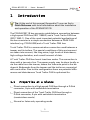
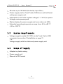
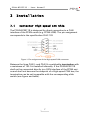
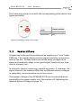
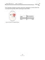
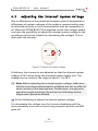
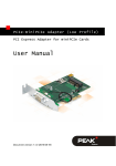
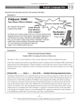
PCAN-B10011S
Bus Converter High-speed CAN
to Truck Trailer CAN
User Manual
Document version 2.1.0 (2013-11-15)
PCAN-B10011S - User Manual
Products taken into account
Product Name
Model
Part number
PCAN-B10011S
IPEH-002041
CANopen® and CiA® are registered community trade marks of CAN in Automation
e.V.
All other product names mentioned in this document may be the trademarks or registered trademarks of their respective companies. They are not explicitly marked by
“™” and “®”.
© 2013 PEAK-System Technik GmbH
PEAK-System Technik GmbH
Otto-Roehm-Strasse 69
64293 Darmstadt
Germany
Phone: +49 (0)6151 8173-20
Fax:
+49 (0)6151 8173-29
www.peak-system.com
[email protected]
Document version 2.1.0 (2013-11-15)
2
PCAN-B10011S - User Manual
Contents
1
1.1
1.2
1.3
2
2.1
2.2
2.3
3
3.1
3.2
3.3
4
4.1
4.2
4.3
5
Introduction
5
Properties at a Glance
System Requirements
Scope of Supply
Installation
5
6
6
7
Connector High-speed CAN Side
Connector Truck Trailer CAN Side
Power Supply
Operation
7
8
9
10
CAN Bit Rate
Listen-only Mode
Master/Slave
10
10
11
Communication Problems
13
Red LED “Error”
Adjusting the Internal System Voltage
Single-wire Operation Modes
Technical Specifications
13
14
15
17
Appendix A
CE Certificate
19
Appendix B
Dimension Drawing
20
Appendix C
Quick Reference
21
3
PCAN-B10011S - User Manual
Module Elements
Low-voltage socket
on page 9
Termination High-speed CAN
on page 7
Connector High-speed CAN
on page 7
Internal system voltage
on page 14
Master/Slave
on page 11
Listen-only mode
on page 10
Error indicator Truck Trailer CAN
on page 13
Connector Truck Trailer CAN
on page 8
Power indicator
on page 9
4
PCAN-B10011S - User Manual
1
Introduction
Tip: At the end of this manual (Appendix C) you can find a
Quick Reference with brief information about the installation
and operation of the PCAN-B10011S.
The PCAN-B10011S bus converter establishes a connection between
a high-speed CAN bus (ISO 11898-2) and a Truck Trailer CAN bus
(ISO 11992-1). One of the most important potential applications of
the bus converter is a simple connection between a PEAK CAN
interface (e.g. PCAN-USB) and a Truck Trailer CAN bus.
Truck-Trailer CAN is a communication connection used between a
towcar and its trailers. The special conditions of this environment
are taken into account, like long wires, high levels of disturbance,
high voltage deviation, and a small amount of data.
A Truck Trailer CAN bus has at least two nodes. The connection is
done with a two-wire line. The power supply may be done locally or
via the cable from the towcar, where the reference point is the bodywork. Bodyworks from the towcar and the trailer are connected
with each other. Due to this configuration there are potential differences and disturbances Truck Trailer CAN is optimized for.
1.1
Properties at a Glance
Direct connection to a High-speed CAN bus through a D-Sub
connector, 9-pin with switchable termination
Direct connection of the Truck Trailer CAN bus through a
D-Sub connector, 9-pin with switchable termination
(master/slave mode)
Normal or listen-only operating mode
5
PCAN-B10011S - User Manual
Bit rates up to 125 kbit/s (limited by input filter)
Power supply via the Truck Trailer CAN bus or self-sufficient
with power supply unit
Adjustable Truck Trailer system voltage (11 - 26 V) for power
through mains power pack
Status display for power supply and error states via LEDs
Extended operating temperature range from -40 to +85 °C
(-40 to +185 °F)
1.2
System Requirements
Voltage supply (usually 24 V DC) via the Truck Trailer CAN
connector (see section 2 Installation on page 7)
- or Voltage supply with the delivered power supply unit
1.3
Scope of Supply
Adapter in plastic casing
Power supply unit
Manual in PDF format
6
PCAN-B10011S - User Manual
2
2.1
Installation
Connector High-speed CAN Side
The PCAN-B10011S is designed for direct connection to a CAN
interface of the PCAN series (e.g. PCAN-USB). The pin assignment
corresponds to the specification CiA® 102.
Figure 1: Pin assignment of the High-speed CAN connector
Between the lines CAN_L and CAN_H a switchable termination with
a resistance of 120 Ω is installed internally. If the PCAN-B10011S
shall not be connected directly to a CAN interface of the PCAN series and shall not become the endpoint of a High-speed CAN bus, the
termination can be set inoperable with the corresponding slide
switch (see figure and table).
7
PCAN-B10011S - User Manual
Termination
High-speed CAN
120 Ω
Switch position
left
none
right
Figure 2: Switch for
High-speed CAN termination
2.2
Connector Truck Trailer CAN Side
For the connection of the Truck Trailer CAN bus a 9-pin male D-Sub
port is used.
Figure 3: Pin assignment of the Truck Trailer CAN connector
Optionally the voltage supply of the PCAN-B10011S can be done via
VBAT (pin 9) (see following section).
8
PCAN-B10011S - User Manual
2.3
Power Supply
The PCAN-B10011S can be supplied either via the Truck Trailer CAN
connector (VBAT, pin 9) or independently via the low-voltage socket
(e.g. with the power supply unit). The DC voltage should be
24 Volts.
Figure 4: Contact assignment of the low-voltage socket
Note: A simultaneous connection of both supply ways isn't problematic, because the power supply with the higher voltage
(usually the one of the power supply unit) is used automatically
because of the circuit design. It is ensured that current cannot
flow from one power supply to the other.
In principle higher or lower input voltages than 24 V may be applied
(8 – 30 V). However, communication errors may occur at high potential differences to system voltages of other Truck Trailer CAN nodes.
You can find hints for solving those problems in section 4.2
Adjusting the Internal System Voltage on page 14.
The green LED on the casing of the PCAN-B10011S indicates an
existing power supply.
9
PCAN-B10011S - User Manual
3
Operation
When putting the PCAN-B10011S into operation, please observe the
following sections.
3.1
CAN Bit Rate
When operating the PCAN-B10011S, it must be ensured that the bit
rate on the High-speed CAN bus matches the one on the Truck
Trailer CAN bus. No conversion or automatic adaptation of the bit
rate is done in the bus converter.
The maximum bit rate is 125 kbit/s (limited by input filter).
3.2
Listen-only Mode
During the active operation mode (normal case) the PCAN-B10011S
can both receive as well as transmit on the Truck Trailer CAN side.
For monitoring the CAN traffic without affecting it the setting for the
passive operation is applicable (listen-only mode). In this case the
transmission unit of the PCAN-B10011S is disconnected from the
Truck Trailer CAN. Also the acknowledgement signal (ACK bit) typically used by CAN is not transmitted.
Note: For a simple point-to-point connection between two
nodes both must be able to receive and transmit. Therefore
only the active operation works in this case.
10
PCAN-B10011S - User Manual
The listen-only mode is set with the corresponding slide switch (see
figure and table).
Operation
mode
Switch position
Normal
Listen-only
right
left
Figure 5: Switch for listen-only mode
3.3
Master/Slave
At least one node must be configured as master on a Truck Trailer
CAN bus. The master determines the signal levels for communication on the bus. Further nodes on the bus being configured as
slaves automatically adapt to the given signal levels and are then
able to transmit, too.
In principle, several nodes may operate as master. If, however, the
signal levels of the masters differ due to different battery voltages
or potentials, communication errors may occur.
The system voltage of the PCAN-B10011S can be adjusted when
supplied by the power supply unit. See section 4.2 Adjusting the
Internal System Voltage on page 14.
11
PCAN-B10011S - User Manual
The selection between master and slave operation is done with the
corresponding slide switch (see figure and table).
Operation
mode
Master
Slave
Figure 6: Switch for Master/Slave
12
Switch position
left
right
PCAN-B10011S - User Manual
4
Communication Problems
This section is dealing with the detection of communication problems and the possibilities of adjustments and settings for the
PCAN-B10011S to analyze those problems and solve them.
Tip: You can find additional information about the properties
and the behavior of the Truck Trailer CAN transceiver B10011S
in the corresponding data sheet, which you can download from
the Atmel website (www.atmel.com).
4.1
Red LED “Error”
The red LED indicates the state of the error output of the Truck
Trailer CAN transceiver. This output is active for the following error
conditions on the Truck Trailer CAN side:
Interrupt on CAN_H
Interrupt on CAN_L
Short circuit between CAN_H and GND
Short circuit between CAN_H and VCC
Short circuit between CAN_L and GND
Short circuit between CAN_L and VCC
Transient disturbance caused by an overvoltage pulse between
CAN_L and CAN_H (e.g. when switching an inductive load)
13
PCAN-B10011S - User Manual
4.2
Adjusting the Internal System Voltage
Due to differences in the potentials between parts of bodyworks or
differences of system voltages of the nodes a communication may
be detected as faulty or the communication may be impossible at
all. When the PCAN-B10011S is supplied via the low-voltage socket,
you have the possibility to adjust the internal system voltage to the
conditions on the bus (usually by decreasing the voltage). This is
done with the trimmer.
+
V
–
Figure 7: Trimmer for system voltage
At delivery the trimmer is pre-adjusted so that the internal system
voltage is 24 V when using the provided power supply unit. The
voltage can be varied in the range of about 11 to 26 V.
Note: Before adjusting the internal system voltage, make sure
that the occurring communication problems are not an effect of
short circuits or line interruptions. Furthermore, a single-wire
operation mode should not be active (see following section
Single-wire Operation Modes).
Do the following to adjust the internal system voltage:
For decreasing the voltage turn the trimmer clockwise until the
communication errors are not occurring anymore and the red LED
goes off.
14
PCAN-B10011S - User Manual
4.3
Single-wire Operation Modes
Usually the Truck Trailer CAN transceiver works with the two data
lines CAN_L and CAN_H. For testing or verification a single-wire
operation can be set up (communication only via line CAN_L or
CAN_H). This is done with two Dip switches on the circuit board of
the PCAN-B10011S.
Do the following to set up the single-wire operation:
In order to access the Dip switches you must open the casing of the
PCAN-B10011S. With a flat tip screwdriver separate the upper and
lower casing parts by carefully pressing into the four gaps and lever
the casing open.
Figure 8: Position of the Dip switches on the circuit board
You can find the possible setup combinations of the Dip switches
(S2-1, S2-2) in the following table. Pay attention to the labels on the
Dip switch block.
Operation mode
S2-1
S2-2
Normal
off
off
Single-wire CAN_L
ON
off
Single-wire CAN_H
off
ON
Transceiver not operational
ON
ON
15
PCAN-B10011S - User Manual
Note: If one of the operation modes beside “Normal” is set, the
red LED indicates an error (see also section 4.1 Red LED “Error”
on page 13).
16
PCAN-B10011S - User Manual
5
Technical Specifications
Power supply
Supply voltage
24 V DC nominal, 8 - 30 V DC possible
Current consumption
about 35 mA (at 24 V)
max. 110 mA
High-speed CAN
Specification
ISO 11898-2
CAN specifications 2.0A and 2.0B
Transceiver
PCA82C251
Connector
D-Sub socket, 9-pin, pin assignment according to
specification CiA® 102
Termination
120 Ω (switchable)
Truck Trailer CAN
Specification
ISO 11992
Transceiver
B10011S
Connector
D-Sub plug, 9-pin
Operation modes
Master/Slave, Normal/Listen-only
Bit rate
max. 125 kbit/s (limited by input filter)
Measures
Size
79 x 43 x 22 mm (L x W x H)
See also dimension drawing in Appendix B on
page 20
Weight
42 g
17
PCAN-B10011S - User Manual
Environment
Operating temperature
-40 - +85 °C (-40 - +185 °F)
Temperature for storage and
transport
-40 - +100 °C (-40 - +212 °F)
Relative humidity
15% - 90%, not condensing
EMC
EN 55024:2011-09
EN 55022:2011-12
EC directive 2004/108/EG
Ingress protection (IEC 60529)
IP20
18
PCAN-B10011S - User Manual
Appendix A
CE Certificate
19
PCAN-B10011S - User Manual
Appendix B
Dimension Drawing
Top view and side view PCAN-B10011S.
The figure does not show the original size.
20
PCAN-B10011S - User Manual
Appendix C
Quick Reference
High-speed CAN Socket
Truck Trailer CAN Plug
Low-voltage Socket
24 V DC nominal, 8 - 30 V DC possible
Slide Switches
High-speed CAN termination
120 Ω | termination off
Truck Trailer CAN:
Master | Slave
Truck Trailer CAN:
Listen-only | Normal
Status LEDs
Green “Power”
Red
“Error”
Voltage supply
Error condition on the Truck Trailer CAN bus
21