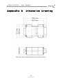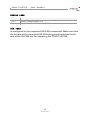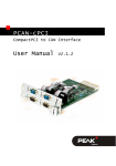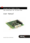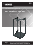
1
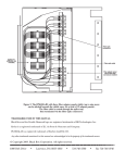
PCAN-TJA1054
Bus Converter High-Speed CAN to
Low-Speed CAN
User Manual
V2.0.0
PCAN-TJA1054 – User Manual
Products taken into account
Product Name
Model
Part number
PCAN-TJA1054
IPEH-002039
CANopen® and CiA® are registered community trade marks of CAN in Automation
e.V.
All other product names mentioned in this document may be the trademarks or
registered trademarks of their respective companies. They are not explicitly marked
by “™” or “®”.
© 2011 PEAK-System Technik GmbH
PEAK-System Technik GmbH
Otto-Roehm-Strasse 69
64293 Darmstadt
Germany
Phone: +49 (0)6151 8173-20
Fax:
+49 (0)6151 8173-29
www.peak-system.com
[email protected]
Document version 2.0.0 (2011-10-05)
2
PCAN-TJA1054 – User Manual
Contents
1
1.1
1.2
1.3
2
2.1
2.2
3
3.1
3.2
3.3
3.4
4
Introduction
4
Properties at a Glance
System Requirements
Scope of Supply
Connectors
4
5
5
6
Connecting the High-speed CAN Side
Connecting the Low-speed CAN Side
Operation
6
7
8
Bit Rate
Low Power Modes
Status LED
Red Error LED
8
8
9
9
Technical Specifications PCAN-TJA1054
10
Appendix A
CE-Certificate
12
Appendix B
Dimension Drawing
13
Appendix C
Quick Reference
14
3
PCAN-TJA1054 – User Manual
1
Introduction
Tip: At the end of this manual (Appendix C) you can find a
Quick Reference with brief information about the operation of
the PCAN-TJA1054.
The PCAN-TJA1054 bus converter establishes a connection between
a High-speed CAN bus (ISO 11898-2) and a Low-speed CAN bus
(ISO 11898-3). One of the most important potential applications of
the bus converter is a simple connection between a PEAK CAN
interface (e.g. PCAN-USB) and a Low-speed CAN bus.
Low-speed CAN (LS-CAN)
The LS-CAN is primarily intended for low-speed applications up to
125 kbit/s in passenger cars. Like the High-speed CAN (HS-CAN) the
LS-CAN transmits signals differentially through two wires. However,
its fault tolerance (e.g. at a short circuit) automatically provides an
operation with only a single wire.
1.1
Properties at a Glance
Adapter from High-speed CAN to Low-speed CAN
Bit rates of up to 125 kbit/s
CAN transceiver NXP PCA82C251 and TJA1054
Termination resistors for Low-speed CAN can be switched
(560 Ohm / 5.66 kOhm)
Power LED
Error LED (Low-speed CAN)
CAN bus connection via D-Sub, 9-pin (in accordance with
CiA® 102)
4
PCAN-TJA1054 – User Manual
Power supply (5 V) through pin 1 of the High-speed CAN
connection. All PEAK CAN interfaces can be set to the required
supply via solder jumper
Extended operating temperature range from -40 to 85 °C
(-40 to 185 °F)
Note: You can find additional information about the properties
and the behavior of the LS-CAN transceiver TJA1054 in the
corresponding data sheet, which you can download, e.g. from
the NXP website: www.nxp.com
1.2
System Requirements
HS-CAN component capable of routing a 5-Volt supply to the
CAN connector (can be set for all CAN interfaces from the PCAN
series)
1.3
Scope of Supply
Adapter in plastic casing
Manual in PDF format
5
PCAN-TJA1054 – User Manual
2
Connectors
2.1
Connecting the High-speed CAN Side
The PCAN-TJA1054 is designed for a direct connection to a HS-CAN
component (e.g. PCAN-USB). The HS-CAN side has a 9-pin D-Sub
connector. The pin assignment corresponds to the specification
CiA® 102.
Figure 1: Pin assignment HS-CAN
Attention! Make sure, that the HS-CAN component always is
turned off when connecting or disconnecting the PCANTJA1054. Otherwise the PCAN-TJA1054 or the connected
hardware may be damaged or destroyed.
Between CAN_L and CAN_H a terminating resistor of 60 Ω is
installed internally. Therefore an additional line termination is not
needed for the connected HS-CAN component.
For power supply the PCAN-TJA1054 uses a direct voltage of +5 V
(Vmain). This must be applied to pin 1 of the HS-CAN connector.
Note: Please see the documentation of the HS-CAN component
the PCAN-TJA1054 shall be connected to, to obtain information
about a power supply on pin 1.
6
PCAN-TJA1054 – User Manual
2.2
Connecting the Low-speed CAN Side
For the connection of the LS-CAN bus a 9-pin D-Sub port is used.
The assignment is as follows:
Figure 2: Pin assignment LS-CAN
Bus termination Low-speed CAN
Every node in a Low-speed CAN has a terminating resistor. For
optimum system conditions the whole CAN bus should be
terminated with 100 Ω (parallel connection of all terminating
resistors). A single node should be terminated with at least 500 Ω
and at most 6 kΩ.
To simplify the adaptation of the PCAN-TJA1054 to an existing CAN
bus you can switch between the terminating resistors 560 Ω and
5.66 kΩ using the slide switch.
For smaller CAN busses or for testing a single component the slide
switch should be set to 560 Ω. For monitoring or configuration of
existing CAN busses, that are already optimized regarding
termination, the slide switch should be set to 5,66 kΩ to minimize an
influence on the total termination.
7
PCAN-TJA1054 – User Manual
3
Operation
3.1
Bit Rate
Make sure that the bit rate of the connected HS-CAN component
matches the bit rate of the LS-CAN bus for operating the PCANTJA1054. No conversion or automatic adaptation of the bit rate is
done in the PCAN-TJA1054.
3.2
Low Power Modes
Note: The LS-CAN transceiver always works with the normal
operation mode. The operation in one of the low-power modes
"Sleep" or "Standby" is not possible.
Because the PCAN-TJA1054 is connected to further hardware
(controllers, for example) only through the CAN bus, it is not
capable of activating one of the low-power modes.
If the PCAN-TJA1054 shall be connected to the LS-CAN bus of a
motor vehicle, that uses a low-power mode, the following should be
considered:
In a low-power mode all transceivers in a motor vehicle terminate
CAN_L against the battery. However, the PCAN-TJA1054 still
terminates CAN_L against VCC. On CAN_L the voltage adjusts to a
level above or below the recognition threshold for short circuits on
CAN_L (7.3 V) depending on the network size and termination.
If the voltage on CAN_L stays below 7.3 V, a shunt current leads to
an increased current consumption in the motor vehicle.
8
PCAN-TJA1054 – User Manual
If however the voltage on CAN_L is above 7.3 V, the PCAN-TJA1054
detects a short circuit on CAN_L and switches to single wire
operation (CAN_H). The communication is ensured but an error is
indicated by the red LED (see section 3.4 Red Error LED).
3.3
Status LED
LED
Meaning
Green
Power, Voltage supply +5 V
Red
Error, Error condition on the LS-CAN bus
3.4
Red Error LED
The red LED indicates the state of the error output of the LS-CAN
transceiver. This output is active for the following error conditions
on the Low-speed CAN side:
Interrupt on CAN_H
Interrupt on CAN_L
Short circuit between CAN_H and GND
Short circuit between CAN_H and VCC
Short circuit between CAN_L and GND
Short circuit between CAN_L and VCC
Short circuit between CAN_H and CAN_L
Please see the data sheet for the CAN transceiver TJA1054 for
further details.
9
PCAN-TJA1054 – User Manual
4
Technical Specifications
PCAN-TJA1054
CAN
High-speed CAN
ISO 11898-2
2.0A (standard format) and 2.0B (extended format
Transceiver: PCA82C251
D-Sub socket, 9 pins (in accordance with
CiA® 102)
Internal bus termination with 62 Ω (fixed)
Low-speed CAN
ISO 11898-3
Transceiver: TJA1054
D-Sub plug, 9 pins
Internal bus termination with 560 Ω or 5.66 kΩ
(switchable)
Bit rate
max. 125 kbit/s
Power supply
Supply Voltage
+5 V = (via pin 1 of D-Sub socket)
Power consumption
Normal operation: 20 – 30 mA
At an Error:
40 mA
Maximum:
80 mA (peak)
Environment
Operating temperature
-40 - +85 °C (-40 to 185 °F)
Temperature for storage and
transport
-40 - +100 °C (-40 to 212 °F)
Relative humidity
15 - 90 %, not condensing
EMC
EN 55024: 2003-10
EN 55022: 2008-05
EC directive 2004/108/EG
Ingress protection (IEC 60529) IP20
10
PCAN-TJA1054 – User Manual
Measures
Size
50 x 32 x 17 mm
See also dimension drawing Appendix B
on page 13
Weight
25 g
11
PCAN-TJA1054 – User Manual
Appendix A
CE-Certificate
12
PCAN-TJA1054 – User Manual
Appendix B
Dimension Drawing
The figure doesn’t show the actual size of the product.
13
PCAN-TJA1054 – User Manual
Appendix C
Quick Reference
High-speed CAN socket
Connect or disconnect the PCAN-TJA1054 only, when the relevant
HS-CAN component is turned off!
Low-speed CAN plug
Slide switch Low-speed CAN termination
560 Ω for building smaller networks, testing single components
5.66 kΩ for monitoring or configuring existing networks (already
terminated optimally)
14
PCAN-TJA1054 – User Manual
Status LEDs
LED
Meaning
Green
Power, Voltage Supply +5 V
Red
Error, Error condition on the LS-CAN bus
Bit rate
Is configured in the connected HS-CAN component. Make sure that
the bit rate of the connected HS-CAN component matches the bit
rate of the LS-CAN bus for operating the PCAN-TJA1054.
15