1
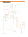
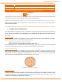
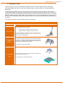
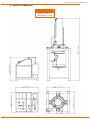
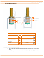
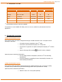
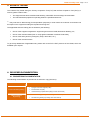
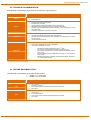
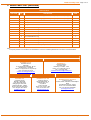
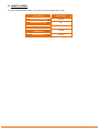
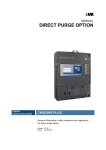
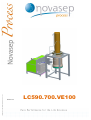
TECHNICAL & PROCESS DESCRIPTION : Dec. 2010
NVS22701
LC590.700.VE100
www.novasep.com
Page 3 of 15
CONTENT
1.
TECHNICAL DESCRIPTION
1.1.
1.2.
1.3.
1.4.
1.5.
1.6.
1.7.
FLOW CHART
TECHNICAL SUMMARY
DYNAMIC AXIAL COMPRESSION
HANDLING TOOLS
WEIGHT & DIMENSIONS
CUSTOMER INTERFACES
REQUIRED UTILITIES
4
4
5
6
7
8
9
10
2.
STANDARDS & NORMS
10
3.
SCOPE OF TESTING
11
4.
DELIVERED DOCUMENTATION
11
4.1.
4.2.
4.3.
ENGINEERING DOCUMENTATION
TECHNICAL DOCUMENTATION
TESTING DOCUMENTATION
11
12
12
5.
SPARE PARTS LIST
13
6.
HOW TO ORDER
14
This confidential document is Novasep’s property. It must not be used, duplicated or transmitted without Novasep’s prior written agreement
www.novasep.com
Page 4 of 15
1. TECHNICAL DESCRIPTION
1.1. FLOW CHART
This confidential document is Novasep’s property. It must not be used, duplicated or transmitted without Novasep’s prior written agreement
www.novasep.com
Page 5 of 15
1.2. TECHNICAL SUMMARY
The LC590.700.VE100 preparative High Performance Liquid Chromatography (HPLC) column is designed for
cGMP operation. Any type of packing material can be used to fill the column provided the proper packing
pressure is chosen to avoid destruction of the particles. It can be operated with the most common solvents
used in chromatography. The column module is composed of the column itself and its compression system
mounted on a stainless steel frame. It can be connected to any pumping system.
MAIN CHARACTERISTICS
Internal Diameter
590 mm
Operating Temperature
5 to 60°C
Maximum Bed Length
400 mm
Compression feature
Dynamic Axial Compression (DAC)
Operating pressure
100 bar
Slurry inlets
1
LC590.700.VE100
ITEM
DESCRIPTION
Column Tube
The internal diameter of the column tube is 590 mm. The standard surface roughness of the column tube ID
is 0.4 µm (15.7 µ inches). The external finish is approximately 1.6 µm (63 µ inches).
Piston and Flange
Column
(1)
The piston and flange of the column contain a woven mesh frit (2µm nominal porosity) and a flow distributor
to provide even distribution of the liquid (”plug flow”) over the cross section of the packed bed. The finish of
the wetted surface roughness of the piston and flange is approximately 0.8µm (30 µ inches)
The flange is sealed to the column tube with a FEP encapsulated "O"-ring and held in place by the use of
screws. The piston is sealed to the column tube with a dynamic spring-loaded seal. The piston seals are
PTFE, FEP encapsulated and SS316L.
Hydraulic Jack
The hydraulic jack is mounted above the column tube. The hydraulic jack has a stroke length of 700 mm,
which allows the user to pack beds of variable lengths. The hydraulic jack exterior is painted steel (Novasep
standard paint).
Hydraulic pumps (2)
An electrical driven pump is used to motion the piston up and downwards. An air driven amplification pump is
used to pressurize the oil and to maintain the dynamic axial compression onto the packing material. The oil
pressure is proportional to the air supply pressure in static conditions (piston not moving).
Emergency Stop
Reset button (3)
Emergency stop to shut down the hydraulic pump in case of emergency. Pneumatic push button to reset the
hydraulic unit after the emergency button has been disengaged
Air supply Valve (4)
Pneumatic 2 way valve, used to supply the hydraulic pump with compressed air.
Motion Selector Oil
distributor (5)
Pneumatic switch to control the oil distributor in order to select the piston’s motion (up, down, stop).
Pressure Regulator
(6)
Air pressure regulator to set the air pressure supply to the pneumatic amplification pump (N°2). The a ir
pressure is linear with the oil pressure.
Filter (7)
Breather filter for the oil reservoir
Filter (7’)
Oil return filter for mounted on the oil reservoir
Oil reservoir (8)
Level indicator (9)
Relief valve (10)
Reservoir for the hydraulic oil with 90L capacity.
Oil level indicator for the oil reservoir.
Oil pressure relief valve to protect the column in case of an accidental over-pressure.
This relief valve can be :
CODAP certified for EU version
ASME Certifed for US version
Pressure gauge (11)
Pressure gauge indicating the oil pressure. This indication is used to determine the bed compression.
Packing valves (12,
13, 14)
Pneumatic 3-way ball valve to isolate the column from the pumping skid for the packing and unpacking
operations and to select solvent direction toward the flange’s or piston’s side during packing operation in
order to bleed the air and/or remove the slurry solvent.
Column state
Selector (15’)
Pneumatic switch to change the column state from elution mode to packing mode by actuating packing
valves.
Purge state Selector
(16’)
Pneumatic switch to change the purge state during packing operation from piston to flange by actuating the
packing valve.
This confidential document is Novasep’s property. It must not be used, duplicated or transmitted without Novasep’s prior written agreement
www.novasep.com
ITEM
Jack isolation valves
(17 & 18)
Sight glass (19)
Pressure transmitter
(20)
Page 6 of 15
DESCRIPTION
Manual 2-way ball valve to isolate the jack for maintenance purposes.
Sigth glass installed on the purge line to identify liquid or air presence during packing operation.
Optional pressure transmitter and its isolation valve. The pressure transmitter can be connected to the
HIPERSEP unit in order to manage (record & alarm) the hydraulic oil pressure.
LC590.700.VE100
Option
The design of the Column is made in such a way to reduce as much dead volume as possible. All wetted parts
of the column module are made of SS316L stainless steel, FEP and PTFE.
Packing valves are high pressure valves with an internal surface finish not better than 2.4 µm (94 µ-inches).
Frame is made of SS304 with an external finish at Grit 220 (about 1.6 µm Ra / 62 µ-inches Ra). External
frame’s welds are grinded.
The LC590.700.VE100 is rated to be operated in ATEX Zone 2 IIB T4 hazardous area (refer to section 2).
1.3. DYNAMIC AXIAL COMPRESSION
The Column Skid is a self packing column. It is based on the Dynamic Axial Compression (DAC) technology.
Its main feature is the presence of a piston attached to a hydraulic jack. The piston travels the entire length of
the column tube. The hydraulic jack is operated by the Hydraulic Unit. The piston has three functions in the
DAC column:
Column Packing
A slurry of packing material in an appropriate solvent, is first transferred into the column tube through 1 side fill
nozzle. The piston is then moved downward thus eliminating :
-
firstly the air through the frit of the column piston,
secondly the slurry solvent through the frit of the column flange.
When the packing process is complete, the piston stops moving. The column is then ready for use. The whole
packing process typically takes less than 20 minutes, including the slurry preparation.
Maintaining Bed Stability
During the column operation, the particles of packing material reorganize over the time and the whole bed
tends to settle, usually forming a void at the fixed bed column inlet with a concomitant decrease in column
performance. The dynamic action of the piston provides continuous compression to the bed and prevents
void formations, thus providing a stable column performance over the time.
Good packing bed arrangement
Column Unpacking
In order to unpack the column, the pressure is released from the hydraulic system and the column flange is
removed. An appropriate sized container is placed under the column tube. The hydraulic pressure is then
increased and the piston is directed downward to push the packing material out of the column and into the
container. The unpacking time is less than 30 minutes.
This confidential document is Novasep’s property. It must not be used, duplicated or transmitted without Novasep’s prior written agreement
www.novasep.com
Page 7 of 15
1.4. HANDLING TOOLS
These accessories, mainly made of SS304L stainless steel, are used to simplify the piston and flange
removal/ installation procedure. They include a manual forklift , a piston rotation unit, a piston table and a
flange table.
The table frame is placed under the column using the manual forklift. The table is lifted up until it comes in
contact with the piston (which has been previously set to its lowest position) or the flange. For the piston, the
special quick release chain attaching the piston to the jack is then opened and the piston sits free on the table.
Finally, the table is lowered, with the piston or the flange on top of it, and can be pulled away. If desired, the
piston can then be attached to the piston rotation unit where it can easily be rotated (to clean/change the frit or
the seals).
The reversed procedure is used to install the piston or the flange.
LC590.700.VE100 HANDLING TOOLS
TYPE
DESCRIPTION
This manual forklift has 2 main functions:
Manual forklift
•
•
Install and remove the piston onto/from the column
Install and remove the flange onto/from the column
The manual forklift mainly is made of SS304. The forklift and all its
components (including wheels) are compliant with ATEX (no
aluminum used in the construction).
Piston
Rotation Unit
This accessory is used to remove the piston from the Piston table
and rotate it for maintenance operations (cleaning/changing piston
frit and seals). The rotating section is designed in such a way that
minimum effort is required to rotate the piston.
This accessory is mainly made of SS304.
Piston/Flange
These tables are used to accommodate the piston and flange once
they are removed from the column.
tables
These accessories are mainly made of SS304.
This confidential document is Novasep’s property. It must not be used, duplicated or transmitted without Novasep’s prior written agreement
www.novasep.com
1.5. WEIGHT & DIMENSIONS
WEIGHT (approximated)
Column : 3500 kg
Hydraulic unit : 470 kg
Manipulating tools : 170 kg
Page 8 of 15
This confidential document is Novasep’s property. It must not be used, duplicated or transmitted without Novasep’s prior written agreement
www.novasep.com
Page 9 of 15
1.6. CUSTOMER INTERFACES
(Connections to hydraulic unit)
2 To pumping skid
3
Slurry inlets
2
Packing purge
Compressed air
2 From pumping skid
1
LC590.700.VE100
TYPE
Compressed Air
ITEM
DESCRIPTION
1
3/4” compression fitting from Swagelok®
2
3/4” compression fitting from Swagelok®
3
1” Triclamp
From pumping skid (HIPERSEP)
To pumping skid (HIPERSEP)
Packing Purge
Slurry Ports
The LC590 column is provided with the following :
•
•
Two 3/4” OD flexible hoses for connection of the Piston and Flange to the Column packing
valves
One (1) set of column tools (wrenches) for assembly, packing/unpacking operations, and
maintenance operations
This confidential document is Novasep’s property. It must not be used, duplicated or transmitted without Novasep’s prior written agreement
www.novasep.com
Page 10 of 15
1.7. REQUIRED UTILITIES
LC590.700.VE100
TYPE
(1)
QUALITY
CAPACITY
PRESSURE
TEMPERATURE
5 Nm3/min (1)
6 barg
Room
7.5 kW1)
NA
NA
Compressed Air
40 µm filtered, oil free, dry
Electricity
400V / 3 Ph / 50Hz
Process
2 µm Filtered
2500 l/h max
100 barg max
5°C to 60 °C
Slurry
Not too viscous
9 m3/h max
0.5 barg max
Room
Thermostation
N/A
N/A
N/A
N/A
During Packing operation otherwise negligible.
The hydraulic oil used is MOBIL DTE FM46, which is a clear oil, suitable for pharmaceutical and food
applications.
2. STANDARDS & NORMS
LC590.700.VE100 EU Version:
As a pressure vessel, the LC590 is designed following the CODAP calculation code. It complies with the
following EC directives:
•
EC Machine Directive 2006/42/EC, May 17th 1998
•
EC Pressure Vessel Directive 97/23/EC, 23rd of May 1997
•
EC Directive for apparatus in explosive atmospheres 94/9/EC, 23rd of March
1994
•
With the following ATEX marking
II3G IIB T4 (IEC / CENELEC)
Optional pressure transmitter (NVS20924):
•
EC Low Voltage Directive 2006/95/EC, December 15th 2004 including
amendments
•
EC Electro Magnetic Compatibility Directive 2004/108/EC, December 12th
2006 including amendments
LC590.700.VE100 US Version:
As a pressure vessel, the LC590 is designed following the ASME calculation code. It conforms to widely
accepted industry standards and good manufacturing practices and is provided with U stamp.
Optional pressure transmitter (NVS20924):
•
Rated for Class 1 Div 2 Group C&D (NEC500)
This confidential document is Novasep’s property. It must not be used, duplicated or transmitted without Novasep’s prior written agreement
www.novasep.com
Page 11 of 15
3. SCOPE OF TESTING
The LC590 is fully tested during the Factory Acceptance Test (FAT) and the Site Acceptance Test (SAT)
order to gather evidence that :
•
The equipment has been manufactured following NOVASEP Process design documentation
•
The manufactured equipment is operating within the specified tolerances
(1)
in
(1)
: Only tests due to dismounting (for transportation purposes) or tests where the customer environment has
an impact on the equipment setting are reproduced during SAT.
The applicable tests are mainly (but not limited to) the following:
•
Check of the equipment against the engineering documents: P&ID, Mechanical Drawing, etc.,
•
Check of the instrumentation (test or verify against calibration certificate if still valid),
•
Check of the safety devices (emergency stops, relief valve, etc.),
•
Check of the critical functions.
To get a fully detailed list of applicable tests, please refer to the FAT & SAT protocols of the LC590, which are
available upon request.
4. DELIVERED DOCUMENTATION
4.1. ENGINEERING DOCUMENTATION
The following documentation is provided as an electronic copy (CD-Rom).
DISCIPLINE
Process Detail Engineering
Mechanical Detail
Engineering
ENGINEERING DOCUMENTATION
•
Piping & Instrument Diagram (P&ID)
•
Process Parts List (PPL)
•
Interfaces Design Specifications (IDS) (Process, Mechanical)
•
General Drawing (including detail drawings nomenclature)
•
General tubing drawings (including item nomenclature)
This confidential document is Novasep’s property. It must not be used, duplicated or transmitted without Novasep’s prior written agreement
www.novasep.com
Page 12 of 15
4.2. TECHNICAL DOCUMENTATION
The following documentation is provided as an electronic copy (CD-Rom).
DISCIPLINE
General
Process
ENGINEERING DOCUMENTATION
•
•
User Manual
Spare Parts List
•
•
•
•
•
Piping & Instrument Diagram (P&ID)
Process Parts List (PPL)
Interface Design Specifications (IDS) (Process, Mechanical)
Manufacturer technical documentation for process components
Material conformity certificates and FDA certificates of the components in contact
with the process
Calibration certificates for process components
•
Mechanical
•
•
•
•
General Drawing (including detail drawings nomenclature)
General tubing drawings (including item nomenclature)
Material conformity certificates and FDA certificates of the components in contact
with the process
Column manufacturer book
•
•
•
Safety instruction
Incorporation declaration EC 97/23 (if applicable)
Incorporation declaration covering :
o
o
o
(1)
Normative
o
o
EC Machine Directive 2006/42/EC, May 17th 1998
EC Pressure Vessel Directive 97/23/EC, 23rd of May 1997
EC Directive for apparatus in explosive atmospheres 94/9/EC, 23rd of
March 1994
EC Low Voltage Directive 2006/95/EC, December 15th 2004 including
amendments
EC Electro Magnetic Compatibility Directive 2004/108/EC, December
12th including amendments
(1)
If this equipment is associated with another NOVASEP equipment like a pumping module, additional
certificates will be provided.
4.3. TESTING DOCUMENTATION
The following documentation is provided as two binders :
• 1 binder copy of the FAT
• 1 binder copy of the SAT
DISCIPLINE
ENGINEERING DOCUMENTATION
FAT
•
•
•
•
FAT Protocol,
FAT test procedures,
Test reports of each individual test performed during the FAT,
FAT report.
SAT
•
•
•
•
SAT Protocol,
SAT test procedures,
Test reports of each individual test performed during the SAT,
SAT report.
This confidential document is Novasep’s property. It must not be used, duplicated or transmitted without Novasep’s prior written agreement
www.novasep.com
Page 13 of 15
5. SPARE PARTS LIST (NVS20429)
LC590.700.VE100
NVS CODE
Qty
DESCRIPTION
ITEM
NVS05500
2
SS316L mesh woven frit for piston (2 µm relative porosity & 5µm absolute porosity).
1
NVS05530
2
SS316L mesh woven frit for flange (2 µm relative porosity & 5µm absolute porosity).
1
NVS06635
2
PTFE guide seal
1
NVS06633
3
PTFE wiper seal
1
NVS06507
3
Spring loaded seal
1
NVS05509
3
FEP covered Silicon O-ring
1
NVS08483
3
FEP covered Silicon O-ring
1
NVS05481
3
FEP covered Silicon O-ring
1
NVS05526
3
FEP covered Silicon O-ring
1
NVS05533
3
FEP covered Silicon O-ring
1
NVS05504
3
FEP covered Silicon O-ring
1
NVS05497
3
FEP covered Silicon O-ring
1
NVS05426
3
FEP covered Silicon O-ring for slurry nozzle
1
NVS09489
1
100 L of hydraulic oil for column jack (DTE FM46)
11
Note :
This spare parts list is not included in the deliverables of a column. Indicated quantities are to be seen as a recommendation.
CUSTOMER SERVICE
EUROPE
USA
NOVASEP Process
Customer Service
Site Eiffel
81, boulevard de la Moselle - BP 50
54340 Pompey - FRANCE
Phone: +33 (0)3 83 49 71 00 (Hot-line)
Fax: +33 (0)3 83 49 70 02
[email protected]
NOVASEP Inc.
Customer Service
23 Creek Circle
Boothwyn, PA 19061 - USA
Phone: +1 610 494 0447 ext. 30
Fax: +1 610 494 1988
[email protected]
ASIA
JAPAN
INDIA
NOVASEP Asia
Customer Service
Build No.1 #306-308,
Lane 898, Halei Road,
Zhangjiang Hi-Tech Park,
Shanghai 201203 - CHINA
Phone: +86 (0)21 3895 0252
Fax: +86 (0)21 5407 0206
[email protected]
NOVASEP Japan K.K
Customer Service
Bunshokudan Bldg. 7F
Kudanminami 1-4-5
Chiyoda-ku
Tokyo 102-0074
Phone: +81 03 3221 1960
Fax: +81 03 3221 1970
[email protected]
NOVASEP Partner, Nishotech
Customer Service
W199-E, MIDC, Khairane, Thane-Belapur
Road
Navi Mumbai-400 705 - INDIA
Phone: +91 22 27781481/82/83
Fax: +91 022 2778 1484/0865
[email protected]
This confidential document is Novasep’s property. It must not be used, duplicated or transmitted without Novasep’s prior written agreement
6. HOW TO ORDER
To place an order please recall in your order the following NOVASEP’s code :
DESCRIPTION
NOVASEP CODE
LC590.700.VE100 CODAP
NVS22701
LC590.700.VE100 ASME
N/A
SPARE PARTS
NVS20429
OPTIONAL PRESSURE
TRANSMITTER
NVS20924
HANDLING TOOLS
NVS22857
This confidential document is Novasep’s property. It must not be used, duplicated or transmitted without Novasep’s prior written agreement
Contacts
www.novasep.com
EUROPE - Novasep Process
Site Eiffel
81, boulevard de la Moselle - BP 50
54340 Pompey - FRANCE
Phone: +33 (0)3 83 49 70 00
Fax: +33 (0)3 83 49 70 02
[email protected]
USA – Novasep, Inc.
23 Creek Circle
Boothwyn, PA 19061 - USA
Phone: +1 610 494 0447
Fax: +1 610 494 1988
[email protected]
ASIA - Novasep Asia
Build No.1 #306-308,
Lane 898, Halei Road,
Zhangjiang Hi-Tech Park,
Shanghai 201203 - CHINA
Phone: +86 (0)21 5407 0208
Fax: +86 (0)21 5407 0206
[email protected]
JAPAN - Novasep Japan K.K
Bunshokudan Bldg. 7F
Kudanminami 1-4-5
Chiyoda-ku
Tokyo 102-0074
Phone: +81 03 3221 1960
Fax: +81 03 3221 1970
[email protected]
INDIA - NOVASEP Partner
Nishotech
Customer Service
W199-E, MIDC, Khairane, ThaneBelapur Road
Navi Mumbai-400 705 - INDIA
Phone: +91 22 27781481/82/83
Fax: +91 022 2778 1484/0865
[email protected]