1
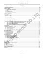
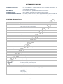
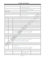
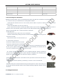
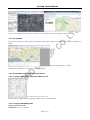
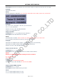
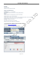
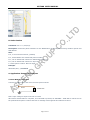
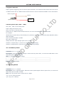
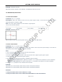
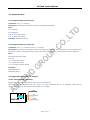
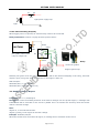
MVT400 USER MANUAL GPS Vehicle Tracker User Manual V1.52 MVT400 Page 1 of 27 MVT400 USER MANUAL Contents 1. 2. 3. 4. Product Overview.................................................................................................................... 3 For Your Safety....................................................................................................................... 3 MVT400 Characteristics ........................................................................................................... 4 Getting Started ...................................................................................................................... 5 4.1 Hardware and Accessories ................................................................................................ 5 4.2 View .............................................................................................................................. 5 4.3 Functional Parts............................................................................................................... 5 4.4 Connecting and Installation ............................................................................................... 7 5. Change Password.................................................................................................................... 7 6. Time Zone ............................................................................................................................. 8 7. Track .................................................................................................................................... 8 7.1 Track by SMS .................................................................................................................. 8 7.2 Track by Calling ............................................................................................................... 9 7.3 Track by Preset Interval .................................................................................................... 9 7.4 Google Earth and Google Map............................................................................................ 9 7.5 Track by 800E ............................................................................................................... 10 7.6 Track by GPRS (Our Protocol) between Server and Tracker................................................... 10 7.6.1 Configure MVT400 by Parameter Editor V1.39............................................................ 10 7.6.2 Configure MVT400 by SMS ...................................................................................... 10 7.6.3 Add MVT400 to 800D web based tracking software ..................................................... 12 8. Authorization ....................................................................................................................... 14 9. Application Examples for Inputs .............................................................................................. 14 9.1 SOS Button Connection .................................................................................................. 14 9.2 Ignition Detection .......................................................................................................... 15 9.3 Analog Input (AD1, AD2……AD8) ...................................................................................... 15 10. Low Battery Alarm .............................................................................................................. 15 11. Speeding Alarm .................................................................................................................. 15 12. Movement/Geo-fence .......................................................................................................... 16 12.1 Movement Alarm ......................................................................................................... 16 12.2 Geo-fence Alarm.......................................................................................................... 16 13. Output Control.................................................................................................................... 17 13.1 Output Control (Immediate) .......................................................................................... 17 13.2 Output Control (Conditional).......................................................................................... 17 13.3 Application Examples for Outputs ................................................................................... 17 13.3.1 Internal Relay (Output1)....................................................................................... 17 13.3.2 External Relay (Output2) ...................................................................................... 18 14. Heading Change Report ....................................................................................................... 18 15. Heartbeat .......................................................................................................................... 19 16. Power Down ....................................................................................................................... 19 17. GPS Antenna Disconnection Alarm ......................................................................................... 19 18. Initialization ....................................................................................................................... 19 19. Password Initialization ......................................................................................................... 20 20. Copyright and Disclaimer ..................................................................................................... 20 Annex 1. SMS Command List ..................................................................................................... 20 Annex 2. Troubleshooting .......................................................................................................... 26 Contacts ................................................................................................................................. 27 Page 2 of 27 MVT400 USER MANUAL 1. Product Overview MVT400 is a GPS/GPRS based tracking device designed for heavy machinery equipment, construction machines and vehicles. MVT400 has inbuilt GPS module to obtain accurate position data and utilizes its GSM capability to send the position data to a specified mobile phone or server base for tracking and management. MVT400 is waterproof (IP66) and has 2 digital inputs, 7 analog inputs, 1 open circuit output and 1 relay output for different reports and applications. MVT400 has the following functions and features:  SMS and GPRS TCP/UDP Communication  Track on Demand  Show Location Directly on Mobile Phone  Track by Time Interval  Inbuilt Motion Sensor for Power Saving  Inbuilt Backup Battery  SOS Panic Button  Movement Alarm  Geo-fencing Control  Low battery Alarm  Speeding Alarm  GPS Blind Area Alarm (in/out)  GPS Antenna Disconnection Alarm  Power-cut Alarm  Voltage Detection for External Power  Engine Cut (Stop Engine)  2 Digital Inputs (1 negative and 1 positive triggering)  7 Analog Inputs  1 OC Outputs  1 Relay Output  1 RS232 Output (Optional)  Waterproof (IP66) 2. For Your Safety Read these simple guidelines. Not following them may be dangerous or illegal. Proper Connection When connecting with other device, read carefully its manual so as to carry out correct installation. Do not connect it to other incompatible devices. Page 3 of 27 MVT400 USER MANUAL Qualified Accessories Use original parts, qualified batteries and peripheral equipments to avoid damage to MVT400. Safe Driving Drivers should not operate this product while driving. Qualified Service Only qualified personnel can install or repair MVT400. Confidential Phone Number For safety reason, do not tell other people the mobile phone number of your MVT400 without taking precautions of security settings. 3. MVT400 Characteristics Items Specification Power Supply +9V - +36V/1.5A (without internal relay) +16V-+36V/1.5A (with internal relay) Backup Battery 850mAh Normal power consumption 85mA/h Dimension 123*83*37mm Installation Dimension 123*103*37mm Weight 350g Operating temperature -20° to 55° C Humidity 5% to 95% Non-condensing Frequency GSM 900/1800/1900Mhz or GSM 850/900/1800/1900Mhz GPS Module latest GPS SIRF-Star III chipset GPS Sensitivity -159dB GPS Frequency L1, 1575.42 MHz C/A Code 1.023 MHz chip rate Channels 20 channel all-in-view tracking Position Accuracy 10 meters, 2D RMS Velocity Accuracy 0.1 m/s Time Accuracy 1 us synchronized to GPS time Default datum WGS-84 Reacquisition 0.1 sec., average Hot start 1 sec., average Warm start 38 sec., average Cold start 42 sec., average Altitude Limit 18,000 meters (60,000 feet) max. Velocity Limit 515 meters/second (1000 knots) max. LED 2 LED lights to show GPS/GSM status. Button One SOS Button(share with Digital Input1) Interface 2 digital inputs (1 negative and 1 positive triggering); 7 analog inputs; 1 OC output; 1 Relay output; 1 RS232 output (Optional). Page 4 of 27 MVT400 USER MANUAL 4. Getting Started This section will describe how to set up your MVT400. 4.1 Hardware and Accessories MVT400 is supplied in a box which includes: MVT400 with GPS Antenna GSM Antenna Socket cables CD Battery 4.2 View Front View Side View 4.3 Functional Parts GPS LED (Blue) On One button is being pressed or input is active Flashing ( every 0.1 second) The unit is being initialized Flashing (0.1 second on and 2.9 seconds off) The unit has a GPS fix Flashing (1 second on and 2 seconds off) The unit has no GPS no fix GSM LED (Green) On One call is coming in / one call is being made Flashing ( every 0.1 second) The unit is being initialized Flashing (0.1 second on and 2.9 seconds off) The unit is connected to the GSM network Flashing (1 second on and 2 seconds off) The unit is not connected to the GSM network Page 5 of 27 Back View MVT400 USER MANUAL Power On/Off Switch(Inside) Open or Close Unit. SOS Button SOS button is connected with the wires. Press it to send SOS alarm to the preauthorized phone number. Mini USB(Inside) Used for firmware update, configuration on PC. (USB-to-Serial Adaptor is required for firmware update, configuration ) SIM Card Holder To insert SIM card here GSM Antenna Connector for GSM antenna (SMA Connector) GPS Antenna Connector for GPS antenna (SMA Connector) Screw Holes There are 4 screw holes on the tracker, 2 along either side that act as fixing points to the vehicle PINs Connector PIN Color Function 12-1 Brown Digital Input 1. Negative triggering. 12-2 Brown Digital Input 2. Positive triggering. 12-3 Brown AD2. 12 Bits Resolution Analog Inputs. Input voltage: 0~50V. 12-4 Brown AD3. 12 Bits Resolution Analog Inputs. Input voltage: 0~50V. 12-5 Brown AD4. 12 Bits Resolution Analog Inputs. Input voltage: 0~50V. 12-6 Brown AD5. 12 Bits Resolution Analog Inputs. Input voltage: 0~50V. 12-7 Brown AD6. 12 Bits Resolution Analog Inputs. Input voltage: 0~50V. 12-8 Brown AD7. 12 Bits Resolution Analog Inputs. Input voltage: 0~50V. 12-9 Brown AD8. 12 Bits Resolution Analog Inputs. Input voltage: 0~50V. 12-10 Black Ground 12-11 Red DC In (power input). No Use Inside Relay Input Voltage: +9V~+36V/1.5A. 12V suggested. Use Inside Relay Input Voltage: +16V~+36V/1.5A. 24V suggested. 10-4 Brown Relay Output COM(250VAC/3A) 10-5 Brown Relay Output NC(250VAC/3A) 10-6 Brown Relay Output NO(250VAC/3A) 10-7 Brown OC Output Low voltage (0V) when effective and open circuit when ineffective. Output open Circuit sink voltage (ineffective): 45V max. Output low voltage sink current (effective): 500mA max. 10-8 Black Ground 10-9 Black Ground 10-10 Red Same As 12-11 DC In (power input). No Use Inside Relay Input Voltage: +9V~+36V/1.5A. 12V suggested. Use Inside Relay Input Voltage: +16V~+36V/1.5A. 24V suggested. DC Characteristics of PINs PIN Inactive Active Maximum DC IN / +9V~+36V/1.5A 45V or +16V~+36V/1.5A AD 2/3/4/5/6/7/8 / 0-50V Page 6 of 27 50V MVT400 USER MANUAL Input 1(Normal Is SOS ) OD/OC or >1V 0V(GND) 45V Input 2 OD/OC or 0V(GND) >3V 45V OC Output Open Circuit 0V (GND) 45V/500mA Relay Output NC connect to COM NO connect to COM 250VAC/3A RS232 Interface / / -12V~+12V 4.4 Connecting and Installation Read this manual before using your MVT400 and check if all parts are included in the packaging box. 4.4.1 Ensure that your MVT400 has a working SIM installed. - Check that the SIM has not run out of credit (test the SIM in a phone to make sure it can send and receive SMS) - Check that the SIM Lock code is turned off - If you require the function of sending an SMS location report to the authorized phone number when it makes a call to the MVT400, please make sure the SIM installed supports displaying caller ID. Before inserting SIM card, cut off the power for MVT400. Install SIM Card - Unscrew and remove the front cover of MVT400. - Insert the SIM card by sliding it into the card slot with the chip module facing to the connectors on PCB. - Put back the front cover and screw it up. 4.4.2 Antenna Connection Connect the GSM Antenna to MVT400. Connect the GPS Antenna to MVT400. - GPS antenna is used to receive satellite signals in the sky. It should be fixed to face the sky (to be placed under the windscreen is recommended) and should not be covered or shielded by any objects containing metal. 4.4.3 Find a suitable place inside the car for installing MVT400. Wiring connections must be firm and reliable and the joints should be wrapped with insulating tape tightly. The unused electrical wire should be properly insulated. Check if all wirings have been connected correctly and then connect the AVL unit to the motor power. Check that the Red LED (Battery) is flashing 1 second on and 2 seconds off. Make a missed phone call the MVT400 using a mobile phone to check if the calling can go through and the MVT400 replies with an SMS indicating longitude, latitude, speed and date. 5. Change Password Command: W******,001,###### Page 7 of 27 MVT400 USER MANUAL Description: Change user’s password. Note: 1. ****** is user’s password and the default password is 000000. The tracker will only accept commands from a user with the correct password. Commands with wrong password will be ignored. 2. ###### is the new password. Password should be 6 digits. Example: W000000,001,123456 W123456,001,999999 6. Time Zone Command: W******,032,T Description: Correct time into your local time Note: 1. Default time of the tracker is GMT 2. This correction is applied to location reports by SMS and SMS alarms. T=0, to turn off this function. T=[1, 65535] to set time difference in minute to GMT. For those ahead of GMT, just input the time difference in minute directly. For example, GMT+8, W000000,032,480 ‘-‘is required for those behind GMT. For example, W000000,032,-120. Example: W000000,032,480 W000000,032,-120 7. Track 7.1 Track by SMS - Track on Demand - Reply with longitude, latitude, speed and date Command: W******,000 Description: Get the current location of the tracker, send this SMS or make a telephone call directly to the tracker and it will report its longitude and latitude by SMS with format as follows:Latitude = 22 32 36.63N Longitude = 114 04 57.37E, Speed = 2.6854Km/h, 2008-12-24,01:50 Example: W000000,000 - Track on Demand - Reply with a Google link Command: W******,100 Description: Send this command to the tracker and then you receive an SMS with an http link. Click on the link then the location can be shown directly on Google Map on your mobile phone. For example: http://maps.google.com/maps?f=q&hl=en&q=22.543908,114.088564&ie=UTF8&z=16&iwloc=addr&om=1 Note: Only smart phones and PDA support this function. Page 8 of 27 MVT400 USER MANUAL Example: W000000,100 7.2 Track by Calling Make a missed call to the tracker and it will report its longitude and latitude by SMS with format as follows:Latitude = 22 32 36.63N Longitude = 114 04 57.37E, Speed = 2.6854Km/h, 2008-12-24,01:50 7.3 Track by Preset Interval Command: W******,002,XXX Description: Set an interval for the tracker to continuously return its location by SMS Note: 1. XXX is the interval in minute. 2. If XXX=000 to turn off tracking by time Example: W000000,002,030 The tracker will send location data back to your mobile phone every 30 minutes. 7.4 Google Earth and Google Map Download Google Earth from http://earth.google.com/. Start Google Earth (For more information about Google Earth please refer to http://earth.google.com/) or go to http://maps.google.com in your Internet Explorer. Input the latitude and longitude that you receive from the tracker by SMS and click the search button. Google Earth or Google Maps will display the location for you. Example: When you receive: Latitude = 22 32 40.05N Longitude = 114 04 57.74E Type as the following picture shows: (Note: you should input the latitude and longitude as: 22 32 40.05N 114 04 57.74E) And then you can find the location of your tracker: Page 9 of 27 MVT400 USER MANUAL Or you can use local map software on PDA or car navigation device to input the coordinates. 7.5 Track by 800E If you have bought our GPS Tracking Software 800E, after proper configuration, you can do tracking on 800E. GPS Tracking Software - 800E Please refer to 800E User Guide for more information. 7.6 Track by 800d web based tracking software 7.6.1 Configure MVT400 by Parameter Editor V1.39 GPS Tracker Parameter Editor V1.39 Please refer to <GPS Tracker Parameter Editor> for more information 7.6.2 Configure MVT400 by SMS Step 1: Set Tracker ID Command: W******,010,ID Page 10 of 27 MVT400 USER MANUAL Description: Send this command to set an ID for the tracker. Tracker ID must not over 14 digits. Example: W000000,010,00001 Notes: On the packing box of MVT400, you can find a white label writes “IMEI, Tracker ID, Terminal ID". Example: The “Tracker ID: 30403969”, and then you should send. W******,010,30403969 MVT400 will reply “SET SIM OK/30403969” Tracker ID is 304043969 now. Step 2: Set APN Command: W******,011,APN,Username,Password Description: Sets APN details for the tracker Notes: APN defaulted as CMNET. Please contact your SIM card provider for your APN name. If no username and password required, just leave them blank. Example: W000000,011,CMNET,Myname,6688 [with APN user name and password] W000000,011,CMNET [without APN user name and password] MVT400 will reply “SET APN OK/CMNET” Step 3: Set IP and Port Command: W******,012,IP,Port Description: Sets IP and Port for tracker for GPRS communication. Notes: Below is our 800D web based tracking server IP and Port. IP: 119.146.223.203 Port: 8886 Example: W000000,012, 119.146.223.203,8886 MVT400 will reply “SET APN OK/119.146.223.203,8886” Step 4: Enable GPRS Tracking Command: W******,013,X Description: Enables GPRS tracking function. Notes: X=1, to enable GPRS tracking via TCP. X=2, to enable GPRS tracking via UDP. Page 11 of 27 MVT400 USER MANUAL Example: W000000,013,1 MVT400 will reply “Open TCP OK” Step 5: Set GPRS Interval Command: W******,014,XXXXX Description: Sets time interval for sending GPRS packets. Notes: XXXXX should be in five digits and in unit of 10 seconds. XXXXX=00000, to turn off this function; XXXXX=00001~65535, time interval for sending GPRS packet and in unit of 10 seconds. In this example, the tracker will send every 30 seconds. Example: W000000,014,00003 The tracker will send every 30 seconds. MVT400 will reply “SET GPRS Timer OK/00003” 7.6.3 Add MVT400 to 800D web based tracking software Please go to http://119.146.223.203 Enter the user name and password we provided. After log in, please go to “Vehicle Manager-Vehicle List” You will see the below window Please click “Add” button, you will see the below window: Page 12 of 27 MVT400 USER MANUAL License Plate: Define by yourself; you can enter A-Z number or Numeric. Very Important Note: Terminal ID and Plate number are unique on the software, you can add once only, you need to delete it from database before adding it again. Only admin account can delete id from database, general user cannot. You do not need to delete and re-add if the device cannot work on software, because it's caused by your wrong sms setting, not the software. Terminal Type: Choose” TE5” SIM card: the SIM card phone number you put in MVT400. Terminal ID: On the packing box of MVT400, you can find a white label writes “IMEI, Tracker ID, Terminal ID". Very Important Note: Please do not omit the minus if there's a minus before the terminal ID. And, Click "Submit", and then you add the car successfully on the software 800d. Put a check mark on the device, and right click, you will see the menu as below picture. Now you can track online. Page 13 of 27 MVT400 USER MANUAL 8. Authorization Command: W******,003,F,P,T Description: Authorize phone numbers for the SOS button (or inputs) for receiving location reports and SMS alarms. Note: F=0, to turn off this function; (default) F=1, Sends SMS to the authorized phone number; P=1, set an authorized number for SOS button (Input 1) P=2, set an authorized number for Input 2 T: Preset phone number. Max.16 digits Example: W000000,003,1,1,88888888 9. Application Examples for Inputs 9.1 SOS Button Connection Connect the SOS button and wires as below picture shows: Input 1 brown SOS Button Note: input voltage to Input must not over 45V After above authorization is complete, once the SOS is pressed, an SOS SMS - “SOS Alarm” will be sent to the preauthorized phone number and then a message with longitude and latitude to follow. Page 14 of 27 MVT400 USER MANUAL 9.2 Ignition Detection Input 2 (positive triggering) can be used for ignition detection. The detection alarm will be sent to the server via GPRS. Please refer to <GPRS Communication Protocol> Alarm Command 0x9999 for more information. Power for ignition Input 2 Battery Ignition Switch 9.3 Analog Input (AD1, AD2……AD8) AD1, AD2……AD8: 12 bit analog input. Input voltage should be 0~50V. AD1 is the value of external power. Please refer to <GPRS Communication Protocol >for more information for AD1……AD8 data. For example: 094506.000,A,2232.5412,N,11404.6919,E,0.00,,290709,,*12|1.7|110|0000|00AA,0267,0fff,0801,0ab0,0 068,0776,0986 AD1 is 0x00AA and AD2 is 0x0267. Max input voltage 50 V Voltage Formula: Input Voltage=(AD*4.6*11)/4096 0x00AA=>170(decimal)=>(170*4.6*11)/4096=2.1001V(voltage) 0x0267=>615(decimal)=>(615*4.6*11)/4096=7.59741V(voltage) 10. Low Battery Alarm Command: W******,004,X Description: When the tracker’s voltage is lower than the preset value, it will send an SMS alarm to the authorized phone number for SOS. Note: X is the preset value of voltage. =0 , to turn off this function =1, <3.3V =2 , <3.4V =3 , <3.5V (default) =4 , <3.6V =5 , <3.7V Example: W000000,004,2 11. Speeding Alarm Command: W******,005,XX Description: Turn on speeding alarm. When the tracker speeds higher than the preset value, it will send an SMS to the phone number for SOS. Note: XX is the preset value of speed and in 2 digits. =00 , to turn off this function =[01, 20] (unit: 10Km/h) Page 15 of 27 MVT400 USER MANUAL Example: W000000,005,08 When the tracker’s speed is over 80km/h, an SMS alarm will be sent out. 12. Movement/Geo-fence 12.1 Movement Alarm Command: W******,006,XX Description: When the tracker moves out of a preset square scope, it will send an SMS alarm to the authorized phone number for SOS. Note: XX is the preset distance to the tracker’s original place =00, to turn off this function =01, 30m =02, 50m =03, 100m =04, 200m =05, 300m =06, 500m =07, 1000m =08, 2000m Example: W000000,006,06 When tracker moves out of this square scope, it will send out an SMS alarm. 12.2 Geo-fence Alarm Command: W******,017,X or W******,117,X Description: Turn on Geo-fencing alarm. When the tracker moves in/out the preset scope, it will send an SMS alarm to the authorized phone number for SOS. Note: 1. 017 is for alarm when tracker moves out the preset scope; 2. 117 is for alarm when tracker moves in. 3. X is the coordinates which include: Lower-left X,Lower-left Y,Upper-right X,Upper-right Y 4. Lower-left X should be less than Upper-right X; 5. All longitudes and latitudes should be in ASCII format as follows:Longitude: DDDMM.MMMM,E/W. 4 places of decimal. ‘0’ is needed to be stuffed if no value available. Latitude: DDMM.MMMM,N/S. 4 places of decimal. ‘0’ is needed to be stuffed if no value available; 6. Send W******,006,00 to turn off Geo-fence function. Example: W000000,017,11404.0000,E,2232.0010,N,11505.1234,E,2333.5678,N W000000,117,11404.0000,E,2232.0010,N,11505.1234,E,2333.5678,N Remarks: 1. Only one alarm can be set in either In or Out; 2. Only one alarm can be set in either Movement Alarm or Geo-fence Alarm. Page 16 of 27 MVT400 USER MANUAL 13. Output Control 13.1 Output Control (Immediate) Command: W******,020,P,F Description: Send this command to control the Output of MVT400 Note: P=1, Output1 P=2, Output2 F=0, to close the output; F=1, to open the output. Example: W000000,020,1,1 13.2 Output Control (Conditional) Command: W******,120,AB or W******,220,AB Description: Send this command to control the Output of MVT400. This command is only workable when the speed is below 10km/h(command 120) or 20km/h(command 220) and meantime GPS is available. Note: AB represents Out1, Out2. If A or B =0, to close the output =1, to open the output =2, to remain previous status Example: W000000,120,10 W000000,220,10 13.3 Application Examples for Outputs 13.3.1 Internal Relay (Output1) MVT400 has an inbuilt relay which supports up to 250VAC/3A. Normally COM is connected with NC. When you send W000000,020,1,1 to MVT400, COM will be disconnected from NC and connected with NO. For example: NO Relay MVT400 NC COM P1 P2 Page 17 of 27 MVT400 USER MANUAL P2 P1 Light power supply loop Light 13.3.2 External Relay (Output2) When bigger power is required, an external relay needs to be connected. Relay Connection: Connect a replay as below picture shows: MVT400 Brow White Relay RLX PIN7 RLX (PIN7) linked with 87 relay for engine-cut 85 87a 86 30 P2 P1 Green Yellow Relay P1 P2 Power for ignition Engine ignition loop Battery Normally two green wires are connected solidly (P1 and P2 are Normal Close[NC] in the relay), when OC output is open, two green wires will disconnect, the engine is then cut. SMS example: W000000,020,2,1 (cut engine) W000000,020,2,0 (cancel engine-cut) 14. Heading Change Report Command: W******,036,degree Description: when the heading direction of the tracker changes over the preset degree, a message with location data will be sent back to the server by GPRS. This is to enhance the accuracy when the tracker makes a direction change. Note: degree=0, to turn off this function. degree=[1,360], to set degree of direction change. Example: W000000,036,90 When the tracker turns more than 90 degree, a message will be sent back to the server. Page 18 of 27 MVT400 USER MANUAL 15. Heartbeat Command: W******,015,data Description: Set an interval for heartbeat. Note: data is the interval in unit of minute data=0, to turn off this function; data=1~65535, set interval for heartbeat. Example: W000000,015,10 In this example, the tracker will send heartbeat every 10 minutes. 16. Power Down Command: W******,026,XX Description: Make the tracker into power down mode(for power-saving purpose) when it is inactive or stationary for a period of time. In Power Down states, GPS stops working and GSM enters sleep and stop sending out message until it is activated by message, incoming calls, movement or any input changes. Note: XX=00, to turn off this function. XX=01~99, to turn on Power Down after a specified period of being inactive (or stationary). It is in unit of minute. Example: W000000,026,10 The tracker will enter power down mode after it is inactive (or nstationary) for 10 minutes. 17. GPS Antenna Disconnection Alarm Command: W******,050,X Description: When the tracker’s GPS antenna is disconnected or cut, it will send an SMS alarm to the authorized phone number for SOS. Note: X=0, to turn off alarm (default) X=1, to turn on alarm. Example: W000000,050,1 An alarm SMS will be received once the GPS antenna is disconnected or cut. 18. Initialization Command: W******,990,099### Description: This is to make all settings (except for the password) back to factory default. Note: Turn on the device, press the SOS button for five times continuously and the red LED will be on, and then send (within 120 seconds) this SMS to the tracker. Page 19 of 27 MVT400 USER MANUAL ### is the ending character and is required in the text message. Example: W000000,990,099### 19. Password Initialization Command: W888888,999,666 Description: This is to make the password back to factory default in case you forget your password. Note: Turn on the tracker, press the SOS button for five times continuously and the red LED will be on, and then send this SMS (within 120 seconds) to the tracker to make the password back to factory default (000000). Example: W888888,999,666 For more details regarding SMS commands, please go to Annex 1 Command List 20. Copyright and Disclaimer © All rights reserved. The information contained herein may be changed at any time without prior notification. This manual nor any parts thereof may not be reproduced for any purpose whatsoever without the express written consent of us, nor transmitted in any form either electronically or mechanically, including photocopying and recording. In no event shall we be liable for direct, indirect, special, incidental, or consequential damages (including but not limited to economic loss, such as loss of profits, loss of use of profits, loss of business or business interruption, loss of revenue, loss of goodwill or loss of anticipated savings) arising out of the use or inability to use the product or documentation, even if advised of the possibility of such damages. Annex 1. SMS Command List Note: ****** is user’s password and the default password is 000000. The tracker will only accept commands from a user with the correct password. Commands with wrong password will be ignored. Description SMS Command Example Track on Demand W******,000 W000000,000 Remarks: To get the current location of the tracker, send this SMS or make a telephone call directly to the tracker and it will report its longitude and latitude by SMS with format as follows:Latitude = 22 32 36.63N Longitude = 114 04 57.37E, Speed = 2.6854Km/h, 2008-12-24,01:50 Track on Demand W******,100 W000000,100 -Google Link Remarks: Send this command to the tracker and then you receive an SMS with an http link. Click on the link then the location can be shown directly on Google Map on your mobile phone. For example: http://maps.google.com/maps?f=q&hl=en&q=22.543908,114.088564&ie=UTF8&z=16&iwloc=addr&om=1 (Note: Only smart phones and PDA support this function.) Page 20 of 27 MVT400 USER MANUAL Change Password W******,001,###### W000000,001,123456 Remarks: To change user’s password. ###### is the new password. Password should be 6 digits. Track by Interval W******,002,XXX W000000,002,030 Remarks: To set interval for automatic timed report. XXX is the interval in minute. If XXX=000 to turn off tracking by time. In this example, the tracker will send location data back to your mobile phone every 30 minutes. Authorization W******,003,F,P,T1 W000000,003,3,1,88888888 (W******,003,F,P,T1,T2) W000000,003,3,1,88888888,99999999 Remarks: To authorize phone numbers for Inputs for receiving location reports or SMS alarms or phone calls. F=0, to turn off this function; (default) F=1, only sends SMS to the authorized phone number; F=2, only calls the authorized phone number; F=3, both SMS and calling P=1, set an authorized number for Input 1 P=2, set an authorized number for Input 2 T1: Preset phone number. Max.16 digits If you need to set different numbers for receiving SMS and phone call, you can then use W******,003,F,P,T1,T2, In this case T1 is the phone number for receiving SMS and T2 for receiving phone call. Low Battery Alarm W******,004,X W000000,004,2 Remarks: When the tracker’s voltage is lower than the preset value, it will send an SMS alarm to the authorized phone number for SOS. X is the preset value of voltage. =0 , to turn off this function =1, <3.3V =2 , <3.4V =3 , <3.5V (default) =4 , <3.6V =5 , <3.7V Speeding Alarm W******,005,XX W000000,005,08 Remarks: When the tracker speeds higher than the preset value, it will send an SMS to the phone number for SOS. XX is the preset value of speed and in 2 digits. =00 , to turn off this function =[01, 20] (unit: 10Km/h) In this example, when the tracker’s speed is over 80km/h, an SMS alarm will be sent out. Movement Alarm W******,006,XX W000000,006,06 Remarks: When the tracker moves out of a preset square scope, it will send an SMS alarm to the authorized phone number for SOS. XX is the preset distance to the tracker’s original place =00, to turn off this function =01, 30m =02, 50m =03, 100m =04, 200m =05, 300m =06, 500m =07, 1000m =08, 2000m Page 21 of 27 MVT400 USER MANUAL Geo-fence Alarm W******,017,X W000000,017,11404.0000,E,2232.0010,N,11505.12 W******,117,X 34,E,2333.5678,N W000000,117,11404.0000,E,2232.0010,N,11505.12 34,E,2333.5678,N Remarks: 017 is for alarm when tracker moves out the preset scope; 117 is for alarm when tracker moves in. When the tracker moves in or out, it will send an SMS alarm to the authorized phone number for SOS. X is the coordinates which include: Lower-left X,Lower-left Y,Upper-right X,Upper-right Y For example, 11404.0000,E,2232.0010,N,11505.1234,E,2333.5678,N Note: 1. Lower-left X should be less than Upper-right X; 2. All longitudes and latitudes should be in ASCII format as follows:Longitude: DDDMM.MMMM,E/W. 4 places of decimal. ‘0’ is needed to be stuffed if no value available. Latitude: DDMM.MMMM,N/S. 4 places of decimal. ‘0’ is needed to be stuffed if no value available; 3. Only one alarm can be set in either Movement Alarm or Geo-fence Alarm; 4. Send W******,006,00 to turn off Geo-fence function. Extended Functions W******,008,ABCDEFGHIJ## W000000,008,1011100011### # Remarks: A=0, turn off the function of sending SMS location report after a phone call is made to the tracker. A=1, turn on the function of sending SMS location report after a phone call is made to the tracker. B=0, location data of NMEA 0183 GPRMC will be interpreted into normal text for easy reading. For example, Longitude = 114 degree - 04 minute -57.74 second, Latitude = 22 degree -32 minute -40.05 second B=1, location data complies with NMEA 0183 GPRMC protocol. For example, $GPRMC,161509.000,A,2232.5485,N,11404.6887,E,0.3,153.7,290709,,*03 C=0, turn off the function to automatically hang up an incoming call. C=1, turn on the function to automatically hang up an incoming call after 4 - 5 rings. D=0, turn off the function of sending an SMS when the tracker is turned on. D=1, turn on the function of sending an SMS to the authorized phone number for SOS when the tracker is turned on. E, defaulted as 1 (the tracker shuts down automatically when the power voltage is lower than 3V). F=0, turn off the SMS alarm when the tracker enters GPS blind area. F=1, turn on the SMS alarm when the tracker enters GPS blind area. SMS is to be sent to the authorized phone number for SOS. G=0, all LEDs work normally. G=1, all LEDs stop flashing when the tracker is working. H, reserved and defaulted as ‘0’ I=0, turn off the function of sending SMS alarm when the extra power of the vehicle tracker is cut. I=1, turn on the function of sending an SMS alarm to the authorized phone number for SOS when the extra power of the vehicle tracker is cut. J, defaulted as 1 ### is the ending character (ABCDEFGHIJ defaulted as 1000100001) Page 22 of 27 MVT400 USER MANUAL Presetting by SMS for GPRS tracking (Ensure that your SIM card supports GPRS connection prior to setting) Set Tracker’s GPRS ID W******,010,ID W000000,010,00001 Remarks: to set a digital GPRS ID for the tracker. GPRS ID must not over 14 digits. Set APN W******,011,APN,Username, W000000,011,CMNET,Name,6688 Password W000000,011,CMNET Remarks: If no APN username and password are required, just input APN only; APN defaulted as ‘CMNET’; APN + username + password should not over 39 characters. Set IP and Port W******,012,IP,Port W000000,012, 220.121.7.89,8500 W000000,012,www.mywebsite.com,8500 Remarks: IP is your server’s IP or the domain name. Port: [1,65534] Set DNS Server IP W******,009,DNS Server IP W000000,009,220.23.4.90 Remarks: In case the domain name you set by the last command (W******,012,IP, Port) doesn’t work, which means your server IP is not properly set. You can first use this command to set DNS Server IP (please check with your DNS server provider for the DNS Server IP) and then redo the command W******,012,IP,Port. Enable GPRS Tracking W******,013,X W000000,013,1 Remarks: X=0, to turn off GPRS tracking (default); X=1, to enable GPRS tracking via TCP X=2, to enable GPRS tracking via UDP Set GPRS Interval W******,014,XXXXX W000000,014,00060 Remarks: to set time interval for sending GPRS packets. XXXXX should be in five digits and in unit of 10 seconds. XXXXX=00000, to turn off this function; XXXXX=00001~65535, time interval for sending GPRS packet and in unit of 10 seconds. In this example, the tracker will send every 600 seconds (10 minutes). Set Heartbeat Interval W******,015,data W000000,015,10 Remarks: to set interval for heartbeat. Data: in unit of minute data=0, to turn off this function; data=1~65535, set interval for heartbeat. In this example, the tracker will send heartbeat every 10 minutes. Heading Change Report W******,036,degree W000000,036,90 Remarks: when the heading direction of the tracker changes over the preset degree, a message with location data will be sent Page 23 of 27 MVT400 USER MANUAL back to the server by GPRS. degree=0, to turn off this function. degree=[1,360], to set degree of direction change. For more information regarding GPRS tracking please refer to <GPRS Communication Protocol> Output Control (Immediate) W******,020,P,F W000000,020,1,1 Remarks: P =1, Output1; =2, Output2; F =0, to close the output Output Control (Conditional) =1, to open the output W******,120,AB W000000,120,10 W******,220,AB W000000,220,10 Remarks: This function is achievable only when the speed is below 10km/h(command 120) or 20km/h(command 220) and meantime GPS is available. AB represents Out1, Out2. If A or B =0, to close the output Sleep Mode =1, to open the output W******,021,XX### =2, to remain previous status W000000,021,02### Remarks: this setting is for power saving. XX=00 turn off sleep mode XX=01 Level I XX=02 Level II ### is the ending character Here is some explanation for the sleep mode. First, assume that the GPS acquisition time is ONE minute. [1] In Level I The GPS module will be working for the first three minutes (i.e. 3 times of acquisition time) and then shut down for ONE minute (i.e. equivalent to acquisition time), and then work again for another three minutes…… [2] In Level II The GPS module will be working for the first two minutes (i.e. twice of acquisition time) and then shut down for ONE minute (i.e. equivalent to acquisition time), and then work again for another two minutes…… Power Down W******,026,XX W000000,026,10 Remarks: to set power down mode when the tracker is inactive (stationary) for a period of time. In Power Down mode, GPS stops working and GSM enters sleep and stop sending out message until it is activated by message, incoming calls, movement or input changes. XX=00, to turn off this function. XX=01~99, to turn on Power Down after a specified period of being inactive. It is in unit of minute. In this example, the tracker will enter power down mode after it is inactive for 10 minutes. Correct Time Difference W******,032,T W000000,032,480 W000000,032,-120 Remarks: Default time of the tracker is GMT, you can use this comment to correct it to your local time. This command is for SMS tracking only. T=0, to turn off this function. Page 24 of 27 MVT400 USER MANUAL T=[1, 65535] to set time difference in minute to GMT. For those ahead of GMT, just input the time difference in minute directly. For example, GMT+8, W000000,032,480 ‘-‘is required for those behind GMT. For example, W000000,032,-120. Set SMS Initials W******,033,P,Char W000000,033,1,help Remarks: this command is to set initial characters for SOS message when input is triggered. P=1, Input1 P=2, Input2 Char is the character in SOS message and max 32 characters 1 SOS Alarm! GPS Antenna 2 Cry For Help! Disconnection W******,050,X W000000,050,1 Alarm Remarks: this command is to enable alarm when GPS antenna is disconnected or cut. X=0, to turn off alarm (default) X=1, to turn on alarm. Set Prefix (Country Code) W******,502,*Data# W000000,502,*+86# Remarks: be advised caution in this setting. Normally, your country code (for example in China it is +86) will be automatically added and displayed prior to a phone number when sending SMS. In this case, you don’t have to do this setting. If the country code is not added, you are required to input the country code, for example, +86, to enable the tracker can send out SMS to your mobile phone. Data: max 10 digits Get Version No. and Serial No. W******,600 W000000,600 Remarks: to get the version and serial number of tracker’s firmware Get IMEI W******,601 W000000,601 W******,901### W000000,901### Remarks: to get IMEI of the tracker Reboot GSM Remarks: to reboot the GSM module of the tracker Reboot GPS W******,902### W000000,902### Remarks: to reboot the GPS module of the tracker Initialization W******,990,099### W000000,990,099### Remarks: Turn on the device, press the SOS button for five times continuously and then send (within 120 seconds) this SMS to the tracker to make all settings (except for the password) back to factory default. ### is the ending character. Password Initialization W888888,999,666 W888888,999,666 Remarks: In case you forget your password, turn on the tracker, press the SOS button for five times continuously and then send this SMS (within 120 seconds) to the tracker to make the password back to factory default (000000). Page 25 of 27 MVT400 USER MANUAL Annex 2. Troubleshooting Problem: Unit will not turn on Possible Cause: Resolution: Wiring was not connected properly Check and make sure wiring connection is in order. Battery needs charging Recharge battery Problem: Unit will not respond to SMS Possible Cause: Resolution: GSM antenna was not installed properly Make MVT400 connected to GSM network. GSM Network is slow Some GSM networks slow down during peak time or when they have equipment problems. Unit is sleeping Cancel sleeping mode Wrong password in your SMS or wrong SMS Write correct password or SMS format format The SIM in MVT400 has run out of credit Replace or top up the SIM card No SIM card Insert a working SIM card. Check in phone that the SIM can send SMS message. SIM card has expired Check in phone that the SIM can send SMS message. Replace SIM card if needed. SIM has PIN code set Remove PIN code by inserting SIM in you phone and deleting the code. SIM is warped or damaged Inspect SIM, clean the contacts. If re-inserting does not help try another to see if it will work. Roaming not enabled If you are in a different country your SIM account must have roaming enabled. Error connecting GSM antenna Make sure the GSM antenna is connected to the GSM interface. Problem: SMS received starts with ‘Last…’ Possible Cause: Resolution: Unit does not have clear view of the sky Move the antenna of the unit to a location where the sky is visible. MVT400 is in an inner place Wait for the target to come out Battery is low Recharge the unit and the GPS will start working. Error connecting GPS antenna Make sure the GPS antenna is connected to the GPS interface. Problem: Unit Fails to Connect to Server via GPRS Possible Cause: Resolution: SIM card in MVT400 does not support GPRS Enable SIM card GPRS function. function GPRS function of MVT400 is turned off Turn on GPRS function of MVT400. Incorrect IP address or PORT Get the right IP address and PORT and reset to MVT400. GSM signal is weak Move the unit to a location with good GSM reception. Page 26 of 27 MVT400 USER MANUAL Contacts If you encounter any problems when using our products, and cannot solve them by yourself, please contact our technical support team by writing an E-Mail to us. We will be pleased to help you. Page 27 of 27