1
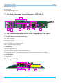
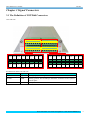
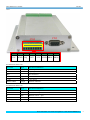
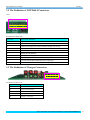
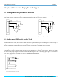
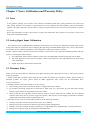
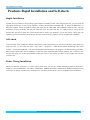
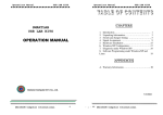
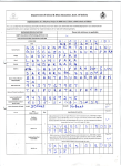
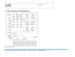
NET2860
User’s Manual
Beijing ART Technology Development Co., Ltd.
NET 2860 user’s manual
V6.203
Contents
Contents ................................................................................................................................................................................2
Chapter 1 Overview ..............................................................................................................................................................3
Chapter 2 Components Layout Diagram and a Brief Description .......................................................................................4
2.1 The Main Component Layout Diagram of NET2860 .............................................................................................4
2.2 The Function Description for the Main Component of NET2860 ..........................................................................4
2.2.1 Signal Input and Output Connectors ............................................................................................................4
2.2.2 Potentiometer ...............................................................................................................................................4
2.2.3 Jumper..........................................................................................................................................................4
2.2.4 DIP Switch ...................................................................................................................................................5
2.3 The Main Component Layout Diagram of NET2860-I...........................................................................................6
2.4 The Function Description for the Main Component of NET2860-I........................................................................6
2.4.1 Signal Input and Output Connectors ............................................................................................................6
2.4.2 Indicator .......................................................................................................................................................6
2.4.3 DIP Switch ...................................................................................................................................................6
2.5 Charger Side Layout ...............................................................................................................................................6
2.6 The Function Description for the Main Component of Charger .............................................................................7
Chapter 3 Signal Connectors................................................................................................................................................8
3.1 The Definition of NET2860 Connectors.................................................................................................................8
3.2 The Definition of NET2860-I Connectors ............................................................................................................10
3.3 The Definition of Charger Connectors..................................................................................................................10
Chapter 4 Connection Ways for Each Signal......................................................................................................................11
4.1 Analog Input Single-ended Connection ................................................................................................................11
4.2 Analog Input Differential-ended Mode .................................................................................................................11
Chapter 5 Notes, Calibration and Warranty Policy............................................................................................................12
5.1 Notes .....................................................................................................................................................................12
5.2 Analog Signal Input Calibration............................................................................................................................12
5.3 Warranty Policy.....................................................................................................................................................12
Products Rapid Installation and Self-check ........................................................................................................................14
Rapid Installation ........................................................................................................................................................14
Self-check ...................................................................................................................................................................14
Delete Wrong Installation ...........................................................................................................................................14
BUY ONLINE at art-control.com/englishs or CALL 86-10-51289836(CN)
2
NET 2860 user’s manual
V6.203
Chapter 1 Overview
In the fields of Real-time Signal Processing, Digital Image Processing and others, high-speed and high-precision data
acquisition modules are demanded. ART NET2860 data acquisition module, which brings in advantages of similar
products that produced in china and other countries, is convenient for use, high cost and stable performance.
ART NET2860 is a data acquisition module based on Ethernet. It can be directly inserted into Ethernet interface to
constitute the laboratory, product quality testing center and systems for different areas of data acquisition, waveform
analysis and processing. It may also constitute the monitoring system for industrial production process.
Unpacking Checklist
Check the shipping carton for any damage. If the shipping carton and contents are damaged, notify the local dealer or
sales for a replacement. Retain the shipping carton and packing material for inspection by the dealer.
Check for the following items in the package. If there are any missing items, contact your local dealer or sales.
¾ NET2860 Data Acquisition Board
¾ ART Disk
a) user’s manual (pdf)
b) drive
c) catalog
¾ Warranty Card
FEATURES
Analog Input
¾
¾
¾
¾
¾
¾
¾
¾
¾
¾
¾
¾
¾
¾
¾
¾
Input Range: ±10V, ±5V, ±2.5V, 0~10V, 0~5V(default)
16-bit resolution
Analog Input Channels: 8-channel/16-channel single-ended inputs or 8- channel differential inputs; you can select
differential input or single-ended input by JP3 and JP5.
When use the single-ended input mode, you can select 8-channel inputs or 16-channels by DIP switch S3.
Sample Frequency: 10K, 15K, 20K or 30K. Be selected by DIP switch S3. But the system’s maximum frequency is
250 KHz.
For single-ended input mode, 8-channel input, sample frequency for each channel can be 10 KHz, 15 KHz, 20 KHz,
25 KHz or 30 KHz.
For single-ended input mode, 16-channel input, sample frequency for each channel can be 10 KHz, 15 KHz.
Flash Memory: 256M, 8M at the part of beginning are used when sampling, others are reservation.
Sample Time: 1s, 2s, 4s, 8s or 16s. Be selected by DIP switch S2.AD conversion time: ≤1.25µs
Programmed Amplifier: AD8251(default), AD8250, AD8253(compatible)
Programmed Gain: 1, 2, 4, 8(default); 1, 2, 5, 10 or 1, 10, 100, 1000
Amplifier Set-up Time: 785ns (0.001%)(max)
Non-linear error: ±3LSB(max)
System Measurement Accuracy: 0.1%
Operating Temperature Range: 0℃~55℃
Storage Temperature Range: -20℃~70℃
BUY ONLINE at art-control.com/englishs or CALL 86-10-51289836(CN)
3
NET 2860 user’s manual
V6.203
Chapter 2 Components Layout Diagram and a Brief Description
2.1 The Main Component Layout Diagram of NET2860
S2
S3
CN3
CN2
CN5
CN4
RP1
JP3
JP5
RP2
JP1
JP2
JP4
2.2 The Function Description for the Main Component of NET2860
2.2.1 Signal Input and Output Connectors
CN2, CN5: Analog input connector
CN3: Ethernet interface, connect with the serial port of NET2860-I
CN4: Power and indictor connector
2.2.2 Potentiometer
RP1: Analog signal input full-scale adjustment potentiometer
RP2: Analog signal input zero-point adjustment potentiometer
2.2.3 Jumper
1. Analog input range selected.
Range
JP1
JP2
JP4
±10V
±5V
±2.5V
0~10V
0~5V
BUY ONLINE at art-control.com/englishs or CALL 86-10-51289836(CN)
4
NET 2860 user’s manual
V6.203
2. Analog input mode selected.
Selection
JP3
JP5
SE
DI
2.2.4 DIP Switch
S3: sample rate, sample channel DIP switch. No. Select sample rate 10K, 15K, 20K, 25K, 30K through 1, 2, 3, 4, 5-bit,
select 8-channel inputs or 16-channels by 6, 7-bit, and 8 bit is reserved. DIP switch dial to "ON", means disconnection,
the other side means connection. Show as the following (black's position is the position of DIP switch):
8
7
16CH
6
8CH
5
30K
4
25K
3
20K
2
15K
10K
ON
SW_RES
1
S3
10 KHz sample rate, 8-channel acquisition
S2: sample time DIP switch. 1, 2, 3, 4, 5-bit corresponding to the sampling time is 1S, 2S, 4S, 8S, 16S, DIP switch dial
to "ON", means disconnection, the other side means connection. Show as the following (black's position is the position
of DIP switch):
5
16S
4
8S
3
4S
2
2S
1
ON
6
7
8
S2
1S
Select 1S sample time
BUY ONLINE at art-control.com/englishs or CALL 86-10-51289836(CN)
5
NET 2860 user’s manual
V6.203
NET2860 default settings:
IP Address: 192.168.2.80
Port NO.: 5001
With 10M/100M adaptive card
2.3 The Main Component Layout Diagram of NET2860-I
CN2
S1
D2
D3
D4
CN5
天线
CN4
CN1
CN3
2.4 The Function Description for the Main Component of NET2860-I
2.4.1 Signal Input and Output Connectors
CN1: Ethernet interface
CN2: Power connector
CN3: Serial port
CN4: +5V charger power supply input port
CN5: +12V power supply output port
2.4.2 Indicator
D2: power supply indicator
D3: electric quantity indicator, it will flash when power on
D4: acquisition indicator, on for normal sample, off for stopping sample, flashing for error sample
2.4.3 DIP Switch
S1: Power Switch
2.5 Charger Side Layout
5 4 3 2 1
LED3, LED2; LED1
J3
CN1
BUY ONLINE at art-control.com/englishs or CALL 86-10-51289836(CN)
6
NET 2860 user’s manual
V6.203
2.6 The Function Description for the Main Component of Charger
CN1: charger interface
LED1: charging indicator. The red indicator is charging error light; the green indicator is charging status light
LED2, LED3: charging electric quantity indicator
J3: can display electric quantity when it is shorted
BUY ONLINE at art-control.com/englishs or CALL 86-10-51289836(CN)
7
NET 2860 user’s manual
V6.203
Chapter 3 Signal Connectors
3.1 The Definition of NET2860 Connectors
CN2 and CN5:
CN2
2 4 6 8 10 12 14 16
2 4 6
1 3
1 3 5 7 9 11 13 15
5 7
9 11 13 15
AGND ADIN1 AGND ADIN3 AGND ADIN5 AGND ADIN7
8 10 12 14 16
CN5
AGND ADIN9 AGND ADIN11 AGND ADIN13 AGND ADIN15
2
4
6
8
10
12
14
16
2
4
6
8
10
12
14
16
1
3
5
7
9
11
13
15
1
3
5
7
9
11
13
15
+5V
ADIN0
+5V
ADIN2
+5V
ADIN4
+5V
ADIN6
+5V
ADIN8
+5V
ADIN10
+5V
ADIN12
+5V
ADIN14
Pin definition about CN2 and CN5:
Pin name
Type
Pin function definition
ADIN0~ADIN15
Input
Analog input, reference ground is AGND.
AGND
GND
Analog ground. This AGND pin should be connected to the system’s
AGND plane.
+5V
PWR
+5V power.
BUY ONLINE at art-control.com/englishs or CALL 86-10-51289836(CN)
8
NET 2860 user’s manual
V6.203
CN4:
CN3
CN4
1 2 3 4 5 6 7 8
1
2
3
4
VIN
DGND
HQ
INIT
5
6
7
8
+12V DGND DBO1 DBO0
Pin definition about CN4:
Pin name
Type
Pin function definition
VIN
PWR
Power input.
DGND
GND
Digital ground.
HQ
No connection.
INIT
Input
Reset.
+12V
PWR
+12V power
DBO0~DBO1
Output
External indicators.
Pin definition about CN3:
Pin name
Type
Pin function definition
1
TX+
Ethernet send + port.
2
TX-
Ethernet send – port.
3
RX+
Ethernet receive + port.
6
RX-
Ethernet receive – port.
4, 5, 7, 8, 9
NC
No connection.
BUY ONLINE at art-control.com/englishs or CALL 86-10-51289836(CN)
9
NET 2860 user’s manual
V6.203
3.2 The Definition of NET2860-I Connectors
CN2:
10 9 8 7 6 5 4 3 2 1
Pin definition about CN2:
Pin name
Pin function definition
1
Digital ground (DGND).
2
Lithium cell charging port, connect with the charger port of CN1.
3
Lithium cell output port, connect with the charger port of CN1.
4
Digital ground (DGND).
5
NET2860 power input port, connect with the VIN of CN4 (NET2860).
6
Digital ground (DGND).
7
NET2860 +12V output, connect with the +12V pin of CN4 (NET2860).
8
Digital ground (DGND).
9
Connect with the D4 of NET2860, drive output port.
10
Connect with the D3 of NET2860, drive output port.
3.3 The Definition of Charger Connectors
5 4 3 2 1
Pin definition about CN1:
Pin name
Pin function definition
1
No connection.
2
Digital ground (DGND).
3
Lithium cell output.
4
Digital ground (DGND).
5
Charger +5V input.
BUY ONLINE at art-control.com/englishs or CALL 86-10-51289836(CN)
10
NET 2860 user’s manual
V6.203
Chapter 4 Connection Ways for Each Signal
4.1 Analog Input Single-ended Connection
Single-ended mode can achieve a signal input by one channel, and several signals use the common reference ground.
This mode is widely applied in occasions of the small interference and relatively many channels.
analog signal
AI0
AI1
AI2
device
AI8
analog signal
AI0
AI1
AI2
device
AI16
device
device
device
device
device
device
AGND
AGND
Figure 4.1 8-ch single-ended input connection
Figure 4.2 16-ch single-ended input connection
4.2 Analog Input Differential-ended Mode
Double-ended input mode, which was also called differential input mode, uses positive and negative channels to input a
signal. This mode is mostly used when biggish interference happens and the channel numbers are few.
Single-ended/double-ended mode can be set by the software, please refer to NET2860 software manual.
According to the diagram below, NET2860 board can be connected as analog voltage double-ended input mode, which
can effectively suppress common-mode interference signal to improve the accuracy of acquisition. Positive side of the
8-channel analog input signal is connected to AI0~AI7, the negative side of the analog input signal is connected to
AI8~AI15, equipments in industrial sites share the AGND with NET2860 board.
Figure 4.3 double-ended input connection
BUY ONLINE at art-control.com/englishs or CALL 86-10-51289836(CN)
11
NET 2860 user’s manual
V6.203
Chapter 5 Notes, Calibration and Warranty Policy
5.1 Notes
In our products’ packing, user can find a user manual, a NET2860 module and a quality guarantee card. Users must
keep quality guarantee card carefully, if the products have some problems and need repairing, please send products
together with quality guarantee card to ART, we will provide good after-sale service and solve the problem as quickly
as we can.
When using NET2860, in order to prevent the IC (chip) from electrostatic harm, please do not touch IC (chip) in the
front panel of NET2860 module.
5.2 Analog Signal Input Calibration
Every device has to be calibrated before sending from the factory. It is necessary to calibrate the module again if users
want to after using for a period of time or changing the input range. NET2860 default input range: ±10V, in the manual,
we introduce how to calibrate NET2860 in ±10V, calibrations of other input ranges are similar.
Prepare a digital voltage instrument which the resolution is more than 5.5 bit, install the NET2860 module, and then
power on, warm-up for fifteen minutes.
1) Zero adjustment: Select AI0 for example; connect 0V to AI0.Adjust RP2 until the actual input value 0.000V.
2) Full-scale adjustment: Select AI0 for example; connect a 9999.69mV to AI0. Adjust RP1until the actual input
value 9999.69mV.
3)
Repeat steps above until meet the requirement.
5.3 Warranty Policy
Thank you for choosing ART. To understand your rights and enjoy all the after-sales services we offer, please read the
following carefully.
1. Before using ART’s products please read the user manual and follow the instructions exactly. When sending in
damaged products for repair, please attach an RMA application form which can be downloaded from:
www.art-control.com.
2. All ART products come with a limited two-year warranty:
¾ The warranty period starts on the day the product is shipped from ART’s factory
¾ For products containing storage devices (hard drives, flash cards, etc.), please back up your data before sending
them for repair. ART is not responsible for any loss of data.
¾ Please ensure the use of properly licensed software with our systems. ART does not condone the use of pirated
software and will not service systems using such software. ART will not be held legally responsible for products
shipped with unlicensed software installed by the user.
3. Our repair service is not covered by ART's guarantee in the following situations:
¾ Damage caused by not following instructions in the User's Manual.
¾ Damage caused by carelessness on the user's part during product transportation.
¾ Damage caused by unsuitable storage environments (i.e. high temperatures, high humidity, or volatile chemicals).
¾ Damage from improper repair by unauthorized ART technicians.
BUY ONLINE at art-control.com/englishs or CALL 86-10-51289836(CN)
12
NET 2860 user’s manual
V6.203
¾ Products with altered and/or damaged serial numbers are not entitled to our service.
4. Customers are responsible for shipping costs to transport damaged products to our company or sales office.
5. To ensure the speed and quality of product repair, please download an RMA application form from our company
website.
BUY ONLINE at art-control.com/englishs or CALL 86-10-51289836(CN)
13
NET 2860 user’s manual
V6.203
Products Rapid Installation and Self-check
Rapid Installation
Product-driven procedure is the operating system adaptive installation mode. After inserting the disc, you can select the
appropriate board type on the pop-up interface, click the button【driver installation】; or select CD-ROM drive in
Resource Explorer, locate the product catalog and enter into the APP folder, and implement Setup.exe file. After the
installation, pop-up CD-ROM, shut off your computer, insert the USB card. If it is a USB product, it can be directly
inserted into the device. When the system prompts that it finds a new hardware, you do not specify a drive path, the
operating system can automatically look up it from the system directory, and then you can complete the installation.
Self-check
At this moment, there should be installation information of the installed device in the Device Manager (when the device
does not work, you can check this item.). Open "Start -> Programs -> ART Demonstration Monitoring and Control
System -> Corresponding Board -> Advanced Testing Presentation System", the program is a standard testing procedure.
Based on the specification of Pin definition, connect the signal acquisition data and test whether AD is normal or not.
Connect the input pins to the corresponding output pins and use the testing procedure to test whether the switch is
normal or not.
Delete Wrong Installation
When you select the wrong drive, or viruses lead to driver error, you can carry out the following operations: In Resource
Explorer, open CD-ROM drive, run Others-> SUPPORT-> USB.bat procedures, and delete the hardware information that
relevant to our boards, and then carry out the process of section I all over again, we can complete the new installation.
BUY ONLINE at art-control.com/englishs or CALL 86-10-51289836(CN)
14