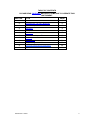
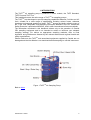
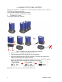
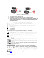
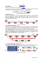
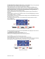
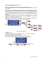
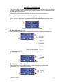
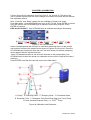
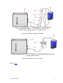
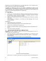
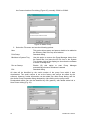
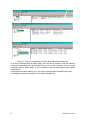
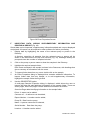
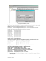
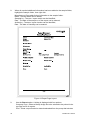
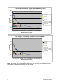
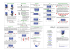
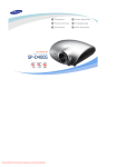
1
TUFF
™
PERSONAL AIR SAMPLING PUMPS
Go to Contact Details
OPERATOR’S MANUAL
HB3343-01
PRINTED IN ENGLAND
CONTACT DETAILS
CASELLA CEL
Regent House,
Wolseley Road,
Kempston,
Bedford,
MK42 7JY, U.K.
Phone: +44 (0) 1234 844 100
Fax: +44 (0) 1234 841 490
E-mail: [email protected]
Web: www.casellameasurement.com
CASELLA USA
17 Old Nashua Road,
# 15, Amherst,
NH 03031,
U.S.A.
Toll Free: +1 (800) 366 2966
Fax: +1 (603) 672 8053
E-mail: [email protected]
Web: www.casellaUSA.com
CASELLA ESPANA
S.A.
Polígono Európolis
Calle C, nº4B
28230 Las Rozas - Madrid
Spain
Phone: + 34 91 640 75 19
Fax: + 34 91 636 01 96
E-mail: [email protected]
Web: www.casella-es.com
CASELLA CHINA
c/o IDEAL INDUSTRIES China
Unit 911, Tower W1, Oriental Plaza,
No1 East Chang An Ave
Dong Cheng District
Beijing 100738
China
Phone: +86 10 85183141
Fax: + 86 10 85183143
E-mail: [email protected]
Web: www.casellachina.cn
Go to Index
2
Casella CEL Limited
TABLE OF CONTENTS
PLEASE READ CAUTIONS BEFORE ATTEMPTING TO OPERATE THIS
INSTRUMENT.
SECTION
TITLE
PAGE
1
Introduction
5
2
Charging the Tuff Unit / Batteries
6
3
Operation Symbols
7
4
Operation
9
5
Configuration
14
6
Calibration
17
7
Renew Inlet Adapter Filter
19
8
Servicing
20
9
Fault Finding
21
10
Pump Management Software
22
11
Technical Information/Certification
35
12
Appendix
39
Casella CEL Limited
3
CAUTIONS:
The TUFF series of air sampling pumps are designed to be robust, however they
should not be dropped or subjected to mechanical shock. Do not suck in water, or
highly saturated or corrosive gases. Failure to comply will render the warranty invalid.
The air sampling pumps contain no user serviceable parts and if a fault is suspected
the instrument must be returned immediately to Casella CEL or to a Casella CEL
Approved Agency for repair.
The warranty does not extend to cleaning or general servicing of the instrument.
Pumps which are not in regular use, or those which have been left on the shelf for
several days, when switched on, may not display a true indication of the current battery
charge status.
To ensure accurate battery condition monitoring and charge status displays, it is
advisable to fully charge the pumps before use.
TM
Back to Index
4
Casella CEL Limited
1. INTRODUCTION
TM
The TUFF air sampling pump is produced in three models, the TUFF Standard,
TUFF Plus and TUFF Pro.
This handbook covers the entire range of TUFFTM air sampling pumps.
The TUFFTM was developed to provide sampling capabilities between 5 ml/min and 4.5
l/min, suitable for a wide range of applications including solvent fumes, asbestos
clearance and personal sampling of dusts. TUFFTM pumps are ideally suited to many of
the “Total” and “Respirable” dust sampling techniques detailed in the U.K. Health and
Safety Executive’s publication MDHS14, and in other international reference methods.
The information contained in this handbook relates only to the operation of Casella
CEL sampling equipment and is not intended to advise or influence your adopted
sampling strategy. For advice on appropriate sampling methods, refer to local
legislation and guidelines as dictated by the relevant national and regional health and
safety organisations.
Please make sure the TUFFTM and associated equipment supplied by Casella are not
damaged and the Inlet Nozzle is not restricted before attempting to use this instrument.
Figure 1 TUFFTM Air Sampling Pump
Back to Index
Casella CEL Limited
5
2. CHARGING THE TUFF PUMPS / BATTERIES
Battery Part numbers: 197088B (4.8 V, High Capacity
197105B 4.8V Standard capacity).
There are two methods of charging the battery.
1.
When the battery is attached to the pump.
2.
The battery on its own.
This section details both methods.
•
•
•
•
Nickel metal- hydride or
Figure 2 Fit Battery to Pump and then to the Charger
Insert pump into charging cradle as shown above.
Fast charge starts and the red LED on the pump flashes.
When fully charged the blue LED will illuminate. The pump can be left in the
cradle on trickle charge or may be removed.
Individual battery packs can also be charged / stored in the cradle. The battery
pack’s own red LED will indicate that charging is in progress.
Battery Charge Mode
Note: Make sure all pumps are fully charged before use.
6
Casella CEL Limited
Figure 3 Insert Battery in Charger
•
•
•
Insert battery into the charging cradle.
Slow charge (>8-14 hours) starts. Red LED on battery illuminates.
Battery fully charged. LED on battery holds steady illumination. The battery can
be left in cradle on trickle charge or removed. The battery charger will power
down after 5 seconds.
3. SYMBOLS DISPLAYED DURING OPERATION
During a sampling run symbols are displayed on the screen to indicate the pump
Running /Stopped status.
The symbol in the top left hand corner of the screen displays the pump mode.
Pump Running.
Pump Stopped.
Pump Paused.
The operating keys can be set in a Partial Lock Mode or Locked Mode.
Partial Lock Mode. This can be activated in Stop Mode and Run Mode. Press
the ON/OFF key three times within 3 seconds to enter Partial Lock Mode. In
this mode the pump can only be started and stopped.
Fully Locked Mode. This can only be activated in Run Mode. Press the
ON/OFF key three times within 3 seconds to enter Locked Mode. In this mode
all keys are disabled.
BATTERY GAUGE
TUFF Standard models – Battery gauge shows approximate estimate of
available battery capacity.
TUFF Plus Model- Here the battery status bar indicates approximate %
remaining.
PRO only - This screen shows the estimated life remaining based on the
current battery loading.
ERROR MESSAGES
The pump stops and an error condition is indicated by a
flashing ‘!’ and red LED. Low Battery and Flow Blockage are
shown here. After 1 minute stoppage the pump will try restart.
All error messages are displayed for 4 hours before the pump
turns off.
This symbol is displayed if the Run Time exceeds 2500hrs or
exceeds 600 charge cycles.
Back to Index
Casella CEL Limited
7
4. OPERATION
A. POWER ON
Note: To Set Language go to Configuration Chapter 5.
To start the pump, press and release the ON/OFF Key. The Firmware will run through
the initialisation screens and then automatically go to the Main Menu.
Figure 4 Power ON Screens
B. MAIN MENU (Fig. 5)
When on the Sampler will scroll through the Main Menu Options. The information
displayed on the screens will be the saved data from the last time the pump was used.
Press the ENTER key on any screen to start the pump. (Volume and Flow not
displayed on Standard Model.)
Figure 5 Main Menu
C. RUN MODE MAIN MENU (Fig. 6)
When the pump is running the Sampler will scroll through the Run Mode Menu options
and the blue led will be flashing. Current run data will be displayed. To stop the pump,
press and hold the ENTER key on any screen until the countdown is complete.
Note: PRO Model Only - Screen (Z) is the remaining run time available based on the
current flow and pressure loading. The Plus model displays the % of remaining battery
capacity only. Standard model only displays battery status bar and elapsed run time
only. No flow rate or sampled volume are displayed.
Figure 6 Run Mode Main Menu
D. STOPPED MODE MENU OPTIONS (Fig. 7)
Use the UP/DOWN keys to step through the Menu Options. Press ENTER to access a
Menu Option when it is displayed. Menu option not available in partial lock mode.
Figure 7 Menu Options
8
Casella CEL Limited
E.TIME WEIGHTED AVERAGE (TWA) PRO and PLUS ONLY (Fig. 8) (Only activated
when advanced mode is selected-see configuration chapter)
This mode allows the user to allow a known volume of sample to be taken over a
selectable time period (for example 120L over 8 hours.). In this instance if the pump
was set to 2l/min flow rate, it would only need to sample for 60 minutes over the whole
8 hour sampling duration. The pump will automatically switch on/off spreading the
sample on time over the whole duration evenly.
Use the UP/DOWN keys to step through the Menu Options until the TWA screen is
displayed.
Press ENTER to continue to the TWA Run screen. Use the UP/DOWN keys to set the
total sampling duration, e. g 8 hours.
Press ENTER to continue to the Exposure time setting. Use the UP/DOWN keys to set
the Exposure Time, e. g 1 hour.
The settings entered will provide 1 hours exposure time evenly spaced over the 8
hours running time.
Press ENTER to Start.
Figure 8 Time Weighted Average
To exit the program at any time press and hold ENTER. The display will count down 3,
2, 1 and default to the Main Menu.
F. RUN DURATION (PRO and PLUS ONLY) (Fig. 9)
Allows a pre set sampling duration time to be set e.g 6 hours.
Press ENTER to access Run Duration setup screen.
Use the UP/DOWN keys to set run duration in hours and minutes.
Press ENTER again to start the pump. The duration will be counted down and indicate
time remaining. The pump will stop when the duration end time is reached.
Figure 9 Run Duration
Casella CEL Limited
9
G. PROGRAM MODE (PRO ONLY) (Fig. 10)
Note: The Advanced Mode must be selected ON to enable this feature.
The program is configured on a PC and then uploaded into the pump. Refer to chapter
10 for details.
Note: If the pump is programmed to start sampling at 08:00 on Monday and the pump
is not switched ON until 08:10 on Monday it will not run until the next Monday at 08:00.
This example assumes the intention is to run the pump for 4 hours, then pause for 1
hour, and then resume running for another 4 hours. Use the UP/DOWN keys to step
through the Stop Mode Menu Options (See Fig. 14 for details) until PRG1 screen is
displayed.
Press ENTER to continue to the ‘ON 1’ screen. Use the UP/DOWN keys to review the
program set parameters. ON1 is 08:00. OFF1 is 12:00. PAUSE is 12:00 – 13:00.
START2 is 13:00. PROGRAM END is 17:00.
When pump is running, to exit Program Mode at any time press and hold ENTER. The
MAIN MENU’s will count own 3, 2, 1 and default to the Main Menu.
Figure 10 Program Mode
H. RESET (Fig. 11)
(Used to reset all the previous run details from display. If run details are required,
please make a note of these before reseting).
Press and hold ENTER. Release ENTER when counter is at zero.
Note: If the counter is already at zero, the Reset option is not displayed.
Figure 11 Reset Function
10
Casella CEL Limited
I. SET REQUIRED FLOW RATE (Fig. 12)
Note: “Set Flow” and “Reset” options are not available in Partial Lock mode.
From START, press UP or DOWN arrow to go to SET FLOW. Press ENTER to access
Set Flow options. Use UP/DOWN keys to adjust the flow setting in 0.5 l/min
increments. (Please note Tuff 3 will only adjust to maximum of 3l/min whilst Tuff 4
models will adjust up to 4.5L/min flow rates.)
Press ENTER to continue.
Pump should then be connected to external flow calibration device.
For External Calibration details refer to Chapter 6.
Use UP/DOWN keys to calibrate the pump flow setting.
Figure 12 Calibration Screens
J. POWERING OFF (Fig. 13)
To stop the pump at any time, press and hold press the ON/OFF Key. A “countdown”
will be displayed and the pump will switch off.
Figure 13 Power OFF Screens
Casella CEL Limited
11
K.USE WITH LOW FLOW ADAPTOR (Fig 14)
This enables the instrument to be used with sorbent tubes at flows down to 5 ml/min.
1. Connect the inlet of a pump to a flow meter such as the Defender or Dry flow meter
and calibrate the flow rate to 1.5 l/min.
2. Stop the pump and disconnect the flowmeter.
3. Starting from the TUFF inlet, connect the following: constant pressure regulator, low
flow adaptor, sorbent tube holder and a flow meter such as the Dry Flow or Dry Cal
shown in Figure 14.
4. Break both ends off a sorbent tube and put it in the holder with the arrow pointing
towards the pump.
5. Start the pump and adjust the flow to the required rate using the screw on the side of
the low flow adaptor.
6. Perform the measurements using a fresh sorbent tube.
Figure 14 Use with Low Flow Adapter
Back to Index
12
Casella CEL Limited
CHAPTER 5 CONFIGURATION
This allows basic settings such as display language and measurement units to be
changed, gives access to Calibration and Duration modes, plus the additional modes
available to Tuff Pro models.
Configuration Mode can be activated only while switching the instrument on.
A. ACCESS CONFIGURATION SCREENS (Fig. 15)
When powering up, simultaneously press and hold the UP arrow. This allows access
to the configuration screens. After approximately 8 seconds the Set Language screen
is displayed.
Figure 15 Access Configuration Screens
B. SET LANGUAGE (Fig. 16)
Use UP/DOWN keys to select a language. Press ENTER to load the language and
continue setup.
Figure 16 Set Language
C. CONTRAST (Fig. 17)
Use UP/DOWN keys to adjust the contrast. Press ENTER to save.
Figure 17 Set Contrast
D. TEMPERATURE (Fig. 18)
Use UP/DOWN keys to select the required unit for displaying the ambient air
temperature (◦C or ◦F) then press ENTER.
Casella CEL Limited
13
Figure 18 Set Temperature
E. VOLUME (Fig. 19)
TUFF + AND PRO ONLY - Use UP/DOWN keys to select the preferred units to display
the sampled volume (i.e. always cubic metres (m3) or AUTO to change automatically
from Litres to m3), then press ENTER.
Figure 19 Set Volume
F. ADVANCED MODE (Fig. 20)
Note: This feature is only available on the ’Pro’ Model and is used to run Program
(PRG) 1 and 2 and the TWA mode.
Use UP/DOWN keys to set the Advanced Mode ON and OFF. Press ENTER to save
the Advanced Mode setting.
Figure 20 Advanced Mode
G. SERVICE LIFE AND SERIAL NUMBER (Fig. 21)
The ‘Life’ shown is the accumulated run time in hours. The Serial number is the unique
number assigned to the pump. Press ENTER to continue.
Figure 21 Service Life and Serial Number Screen
H. CALIBRATE YES / NO (Default Calibration / Tuff Plus and Pro Only) (Fig.: 22)
Use UP/DOWN keys to SELECT Yes/No.
Activates Calibration Mode, which allows the entire calibration for the pump to be reset,
based on a two point calibration. The instrument will have been accurately calibrated at
the factory prior to delivery. (Tuff Standard models cannot be adjusted via this facility.)
Therefore it is recommended that this operation be performed only as part of a routine
service or when a suspected error has occurred (see chapter 9).
ONLY ALTER THESE SETTINGS AFTER DISCUSSIONS WITH CASELLA SERVICE
DEPARTMENT OR DISTRIBUTORS.
NO – The operating system will take you back to the MAIN MENU.
YES – The system will prepare the unit for 2 point calibration.
Connect the pump to the calibration equipment (Refer to Chapter 6)
ENTER - Press ENTER to continue.
14
Casella CEL Limited
Figure 22 Calibrate Screen
I. ADJUSTMENT OF LOW SET POINT (Fig. 23)
Use UP/DOWN keys to alter the low set point in l/min. Press ENTER to continue. The
pump will start.
Figure 23 Low Set Screen
J. CALIBRATION OF LOW SET POINT (Fig. 24)
Check the external calibrator reading equals the low set point value. Use UP/DOWN
keys to adjust the flow rate until they are equal. Press ENTER to save the new setting
and continue.
Figure 24 (Low Set) Adjust Screen
K. ADJUSTMENT OF HIGH SET POINT (Fig. 25)
Use UP/DOWN keys to alter the high set point in l/min. Press ENTER to continue.
Figure 25 High Set Screen
L. CALIBRATION OF HIGH SET POINT (Fig. 26)
Check the external calibrator reading equals the high set point value. Use UP/DOWN
keys to adjust the flow rate until they are equal. Press ENTER to save the new setting
and continue.
The pump will stop and the unit will default to the MAIN MENU.
Figure 26 (High Set) Adjust Screen
Back to Index
Casella CEL Limited
15
CHAPTER 6 CALIBRATION
Perform Single Point Calibration (Set Flow) Figs 27, 28, 29 and 30. This allows the
user to set the required flow rate for the sample to be taken and check with an external
flow calibration device.
Note: “Flow Set” and “Reset” options are not available in Partial Lock mode.
From Main Menu , press UP/DOWN keys to go to SET FLOW. Press ENTER to access
Set Flow options. Use UP/DOWN keys to adjust the flow setting required. Press
ENTER to continue.
PRO and PLUS ONLY - Use UP/DOWN keys to calibrate the Sampler flow setting.
Figure 27 Set Up Calibration
Attach a sampling head and flow tube or other flow-measuring device to the pump’s
inlet nozzle to measure the actual flow as shown in Figures 28, 29 and 30. Press the
UP/ DOWN keys to adjust the flow rate until the value shown on the flow measuring
device agrees with the required flow rate.
(Note Tuff standard models do not show the flow rate on the pump display. Use
UP/DOWN keys to alter flow shown on calibration device until the required flow rate is
reached.)
Press ENTER to set the flow rate and return to the Main Menu.
A. Clamp B. Sampling Head C. Clamping Studs D. Flowmeter Stand
E. Rotameter Tube F. Rotameter Float (Read Flow Rate from Top of Float)
G. Hose (Nominal Diameter 5mm) H. TUFFTM Pump
Figure 28 Calibration with Rotameter
16
Casella CEL Limited
A. Clamp B. Sampling Head C. Clamping Studs D. Flowmeter Stand
E. (Typical) Digital Calibrator F. Hose (Nominal Diameter 5mm)
G. Hose (Nominal Diameter 5mm) H. TUFFTM Pump
Figure 29 Calibration with Digital Calibrator
A. Cyclone Sampling Head
B. TUFFTM Pump C. Hose (Nominal Diameter 5mm) D.
(Typical) Digital Calibrator
Figure 30 Calibration with Cyclone Head
Back to Index
Casella CEL Limited
17
CHAPTER 7 RENEWING THE INLET FILTER
Note: The filter element should be replaced every 3 months. The pump running
time and the operating environment can reduce this time considerably.
1.
2.
3.
4.
Remove the Inlet nozzle.
Discard the Filter Element.
Fit a new Filter Element.
Fit and hand tighten the Inlet nozzle.
Figure 31 Renewing Inlet Filter
Packs of 5 Inlet Adaptors:
Filters are available in packs of 10:
Part number: 197113A.
Part number: 197114A
Back to Index
18
Casella CEL Limited
CHAPTER 8 SERVICING
Casella CEL’s in house service department offers a comprehensive range of repair and
calibration services designed to maintain a fast and efficient back-up for all our
products. The Service Department is operated under the scope of our BSI registration
for products manufactured by us. We will however, undertake the repair of other
manufacturers equipment.
For further information please contact our service department at our UK headquarters
or via approved servicing distributors. We will be happy to provide quotations for
individual repairs or provide annual maintenance under contract.
We recommend factory service by technicians trained and equipped to repair your
instrumentation. Should you wish factory repair assistance, send your equipment in a
package equivalent to the original packaging. Insure to full value and ship prepaid.
Include a letter giving full details with your packing list and send to the Casella CEL
Service Department at Bedford.
For service outside the United Kingdom, please return to our appointed distributor.
MAINTENANCE
TM
Your TUFF Personal Air Sampling Pump is designed to provide long and reliable
service. Routine maintenance is minimal.
Make sure the battery pack never stays in a discharged condition.
Replace inlet filters regularly (see chapter 7). Keep the instrument body clean.
Do not operate without a filter connected to the inlet. Ingested dirt and dust particles
may cause internal damage, malfunction or erratic flow.
Schematic showing service kit parts:
Back to Index
Casella CEL Limited
19
CHAPTER 9 FAULT FINDING
The following table outlines some possible fault conditions.
SYMPTOM
Failure to switch
ON
Pump runs fast
Poor control
response,
Non-repeatable
flow settings
Not getting
expected run time
from pump
FAULT
SUGGESTED REMEDY
Battery not
charged.
Does the red
charger LED
illuminate?
- Check that the battery is secured.
- Clean the battery connectors on the TUFF
pump.
- Clean the battery connectors on the charger.
- Push the TUFF pump firmly into the charger.
- Charger fault - return for repair.
- Keypad fault - return for repair.
Software locked
up?
Disconnect the battery for a minimum of 20
minutes and then reconnect the battery. If this
fails, return for repair.
Control error
Leakage
Higher back
pressure from
filter media
Damaged flow pressure sensor - return for
repair.
Water ingress - clean or return for repair.
Tubes to sensor squashed or damaged return for repair.
Electrical fault - return for repair.
Calibration error - perform fundamental
calibration in Configuration Mode.
Contamination or damage to valves
- return for repair.
Check all connections.
If internal leakage is suspected - return for
repair.
Ensure Tuff is fully charged. Consult filter back
pressure tables to calculate correct run time.
Often by selecting coarser filter material will
offer considerably longer run times.
Back to Index
20
Casella CEL Limited
CHAPTER 10 PUMP MANAGEMENT SOFTWARE
NOTICE!
CASELLA INSIGHT™ DATA MANAGEMENT SOFTWARE
Tuff Pro and Apex Pro personal air sampling pumps can now be programmed
and data downloaded for management purposes via the new Casella Insight™
Data Management Software. Please refer to separate product datasheet and
handbook or contact Casella technical support team for further details.
PUMP MANAGER INTRODUCTION
Casella CEL Pump Manager application software is designed to be used with the
Casella TUFFTM Pro and Apex Pro models of personal air sampling pumps and offers a
convenient way to store, manage and present sample data.
This software allows the Duration, TWA and User Program Modes of TUFFTM Pro
pumps to be programmed. In addition, it saves sample results together with extra
information related to the sample, and prints comprehensive reports.
Communication between the PC and pump is via a USB infrared transducer. Once the
infrared transducer has been connected to the PC’s there will be no need to connect
(and disconnect) cables between instrument and PC to facilitate communication. This
eliminates wear and tear on any connectors and cables. All infrared communication is
fully error checked to prevent data corruption.
The software must be installed (Section B) and infra-red communication established
(Section C) before data can be downloaded from a TUFF Pump to a PC.
Pump Manager can be left running in the background on the Windows system as an
icon. When a pump comes within range of the infrared computer link, the application
will wake up and download data from the pump and store it in a database. It is possible
to configure Pump Manager to start up in background scanning mode when Windows
starts, thus minimising the amount of user intervention required.(Please note: If any
pump comes in the close proximity to the IR interface, any current run mode will
be terminated).
All data is stored in a database and identified according to the TUFF pump from which
it was downloaded, and optionally by details of the person who used the pump. This
helps to maintain traceability of data. All data is automatically stored when it is
changed, so if you have a system failure (e.g. power failure) you should not lose any
data.
B
SOFTWARE INSTALLATION / UN-INSTALLATION ON WINDOWSTM 95, 98,
ME, NT 4, XP & 2000
SYSTEM REQUIREMENTS:
- IBMTM compatible PC with Pentium II or better processor;
- At least 8 MB of free RAM space;
- Microsoft Windows 98/ME/2000/XP and NT 4/95 with IE4 or later;
- Hard drive with at least 5 MB of free space;
- Software supplied on CD for program installation;
- Super VGA colour monitor (1024 x 768 16 M colours recommended);
- Mouse or other Windows compatible pointing device;
- Printer - optional.
Pump Manager is supplied on CD. It is advisable to ensure that no other applications
are running while installation takes place. The Setup program for Pump Manager will
install files in the specified program directory and the Windows\System directory. It will
Casella CEL Limited
21
also add an icon to the desktop and a new folder and item to your Programs menu,
either of which can be used to start Pump Manager.
If installing on Windows 95, first run the program TapiUpdate.exe placed in the
installation folder. This updates the version of TAPI on the PC to the version required
by Pump Manager. When installing on Windows 98, Windows NT or later systems, this
update is not required and SHOULD NOT be performed.
INSTALLATION
1.
Start Windows.
2.
Insert the CD. The Pump Manager software automatically detects the language of
the operating system during the installation. Languages supported include
English, French, German, Spanish and Italian.
3.
Wait for the Casella welcome screen to be displayed, then follow the on-screen
instructions.
Once installation is complete, you will find the Pump Manager icon on your
Windows desktop.
UN-INSTALL
1.
Click the Start button on the task bar.
2.
Select the Settings/option and click on the Control Panel option.
3.
Double click on Add/Remove Programs icon.
4.
In the list of installed software, select Pump Manager and click the Add/Remove
button.
5.
Follow the on-screen instructions.
C
ESTABLISHING INFRARED (IR) COMMUNICATION
WARNING: DO NOT attempt to install or use the IR communication link for I.S.
versions while in the hazardous area.
1.
Start Pump Manager by double clicking on its desktop icon, by entering its name
in the RUN menu obtained via the Start button Run option, or using Start –
Programs/option.
The Pump Manager top level window (Fig. 32) will be displayed.
Figure 32 Pump Manager Window
As the cursor is moved to each button, the relevant function will be displayed on
22
Casella CEL Limited
the message line at the bottom left of the display.
2.
Click the Pump button and select the Communications/option.
A Communication Port dialog is displayed (Fig. 33).
Figure 33 Communication Port Dialog
2.
With the ‘Use USB interface’ option ticked, Pump Manager will automatically
detect the presence of a Casella IR Interface and use it to communicate with the
pump. If program is run without USB IR device fitted the following screen will be
seen (Fig. 32):
Figure 34 Program Run without USB IR Device Fitted
Leave this option un-ticked if you are using an earlier (RS-232 based) IR interface
(CMC39) and select the required COM port from the drop-down list.
Specify the port used by the IR link, then click OK to confirm the choice.
An active IR link icon should be shown in the System Tray to the right of the
Status Bar at the bottom of the PC display. This indicates that the device is
waiting to communicate with an TUFF Pump.
Best communication with the pump is achieved when the IR link is positioned in
line with the IR interface window of the pump, with the two devices no more than
60 cm (2 ft) apart.
The fold out sheet at the back of this book shows a diagram of the main menus
and options available from Pump Manager software.
D.
CONFIG. URING THE SOFTWARE AND ADDING A PUMP
Select a communication port then Add Pump (Fig. 34) and Add Person (Fig. 35)
identities to the software as follows.
1.
Select the Pump menu and see the following options.
Communications
Specifies the communication port to be used by the IR
Transducer
Program
Allows the TWA and the two user defined programs
available to the TUFF Pro to be edited and sent to the
pump as described in Section E
2. Select the Communications option and then choose the port to be used from
Casella CEL Limited
23
the Communications Port dialog (Figure 35), normally COM1 or COM2.
Figure 35 Add a Pump
3. Select the File menu and see the following options:
New
This option allows pump and person details to be added to
the Directory field in the top level window
Print Setup
Standard dialog
Minimise to System Tray
Use this option to remove the Pump Manager button from
the Status Bar, but leave the IR link icon in the System
Tray (bottom right of the display) to show that the software
is active in background
Run on Startup
Enable (Ö) this option to start Pump
automatically whenever Windows is started
Exit
Standard dialog
Manager
All data will be identified by the serial number of the pump from which it was
downloaded. The serial number is set at the factory and cannot be edited by the
software. However, further information can be added via a New Pump dialog, and via
the similar Pump Properties dialog obtained by right clicking on the pump name.
Downloaded results can also be identified by user (person), with details added via a
New Person dialog (Fig. 36).
24
Casella CEL Limited
Figure 36 Add a (New) Person
4.
On the File menu, select New followed by Pump to add a new pump, (or right
click on the name of an existing pump) to display its details. (A New Pump
dialog is displayed automatically whenever the soft-ware detects an unknown
pump within range of the IR Transducer.)
The New Pump dialog has the following options:
Delete
Standard dialog.
Properties
Offers the following options
ID
Alphanumeric characters can be entered to identify a
specific sampling pump
Serial Number
(factory set)
Seven numeric characters
Notes/Service History
Allows separate notes to be included about the pump and
its service history
Add a pump ID, Notes and Service History (such as date of last service, or date
of next service) as required.
5.
6.
When data is also to be identified by user, select New followed by Person to
add a new person, (or right click on the name of an existing person) to display
their details on the New Person dialog.
Delete
Standard dialog.
Properties
Offers the following options
Name
Alphanumeric characters of the person’s name can be
entered
ID
Alphanumeric characters to identify the person can be
entered. Job Title, Additional information, Department
Additional information
Notes - allows separate notes to be included about the person.
7.
Add a person’s Name, ID (for example a payroll number), Job Title, Department
and Notes as required.
8.
Select the View menu and see the following options:
Toolbar
Standard dialog
Status Bar
Standard dialog
Units Offers Options to:
Display temperature in oC or oF;
9.
Display volume in ml, Ltrs or m3
Choose temperature and volume units to suit the task.
E
DOWNLOADING DATA
WARNING: DO NOT use the IR communication link for I.S. versions while in a
hazardous area.
Data is downloaded from pump to PC automatically with a minimum of user
intervention. When Pump Manager is running (showing the active IR link icon ), it
transmits a request every second via the transducer, asking for data from any TUFF
Pro within range.
Casella CEL Limited
25
Figure 37 Typical Pump Manager Screen during Download Sequence
If no pump containing data is within range, there will be no response, and the software
continues transmitting the request and listening for a reply. However, when a pump
containing data is within range, it will be detected and the download process started
automatically.
A Data Download status dialog (Fig. 38) will be displayed which identifies the pump
and displays progress messages for the download operation.
26
Casella CEL Limited
Figure 38 Typical Data Download Dialog.
When all data has been downloaded, the software clears the data from the pump
memory.
When any TUFF or Apex pump is actively sampling or running a program, they MUST
BE KEPT AWAY from the IR Transducer. This prevents the Transducer from trying to
empty the pump of any saved data and interrupting the current data sample.
If a pump is detected that has not been configured by the software, (is not included in
the Pump Manager Directory field), a “New Pump” message will be displayed (Fig. 35)
and the new pump added automatically to the application.
The operator should add the remaining pump properties as soon as possible. (A TUFF
Standard model will be shown as a pump with no data.)
If People have been defined, the option will be offered
person who has been using the pump, or to select No Pump User.
to
select
the
The downloaded data is stored in the application database where it is identified by
pump, and when defined, also by person. The display is updated to include the new
data in a “sample” (run) folder that shows each time the pump was switched ON and
OFF as a separate “event” (Fig. 39)
Casella CEL Limited
27
Figure 39 Event Properties Screen
F
INSPECTING DATA, ADDING SUPPLEMENTARY INFORMATION AND
PRINTING A REPORT (Fig. 40)
Stored data can be inspected, supplementary information added and a report displayed
and printed. All reports can be exported to other software for further processing.
1.
Display data by highlighting the name of the relevant pump or person in the
Directory.
A directory containing all samples from the selected pump or person will be
shown in the Data area of the top level window (Fig. 33). Headings identify the
pump and show the number of samples included.
2.
Click on the pump or person name to show the samples in the Directory.
3.
Highlight the required sample folder.
Each event contained in the sample is shown in the Data area, with headings that
give a summary of information from the event.
4.
To inspect further data from any event, double click on the sample.
5.
An Event Properties dialog is displayed that contains additional information. To
inspect further data from any sample, or to add supplementary information,
highlight the sample folder then right click
6.
Use the PROPERTIES option.
A multi-page Sample Properties dialog is displayed, which allows the user to
inspect the data and add additional information to the sample folder. There are
seven pages, where the pages contain additional information as follows.
Overview Page adds identifying information to the sample folder.
Client - A name can be added,
Contract ref.: - A reference can be added,
Report Number - A number can be added,
Pump ID - Data from the pump,
Name - A person name can be selected,
Serial Number Data from the pump,
Location - A location can be added.
28
Casella CEL Limited
Figure 40 Sample Run Folder
The Process Page adds details of the process and substances involved to the sample
folder.
Process notes Field for adding detailed information about the process,
Substances Field for adding detailed information about the substances involved.
Sample data Page contains data downloaded from the pump:
Starting time
- Downloaded data;
Starting date
- Downloaded data;
Ending time
- Downloaded data;
Ending date
- Downloaded data;
Sample period - Downloaded data;
Set flow rate
- Downloaded data;
Average temp. - Downloaded data;
Sample volume - Downloaded data.
Calibration Page allows calibration information to be added and applied to the data:
Use calibration data - Tick to use the displayed information;
Calibrator S/N
- Allows a serial number to be added;
Initial flow
- Field for a flow rate to be entered;
Final flow
- Field for a flow rate to be entered;
Sample period
- Field for a measurement period to be entered.
Analysis Page adds analysis information to the sample folder:
Sample number - A sample identity can be added;
Sample data
- Sample analysis information can be added.
Analytes Page adds details of up to 9 analytes to the sample folder:
Analyte1 Etc. - Analyte identities can be added;
Exposure time - Allows an exposure time to be added.
7.
Enter information into these dialogs as relevant to the particular sample folder or
report (Fig. 40).
Casella CEL Limited
29
8.
When all required additional information has been added to the sample folder,
highlight the sample folder, then right click.
Miscellaneous Page adds further information to the sample folder:
Notes - General notes can be added;
Sampled by - The user / report author can be identified;
Date - The date of the sample or of the report can be entered;
Audited by - The data / report checker can be identified;
Date - The date of checking can be entered.
Figure 41 Report Page Layout
9.
30
Use the Report option. A dialog is displayed with four options:
Company Logo - Allows a bitmap image file to be selected to be printed in the
top right corner of reports;
Print - Prints a report based on data downloaded from the pump that includes
Casella CEL Limited
information entered via the Sample Properties dialog;
The layout of a Pump manager report is shown in Figure 41.
Print Preview - Displays a preview of the printed report.
Copy - Copies the report to the PC clipboard, so it can be pasted into a word
processor and customised. The pasted report has minimal formatting and
may require minor layout work such as font sizes and tab setting.
G
CREATING AND LOADING PUMP PROGRAMS
All operations to create and load pump programs for the TUFF Pro are controlled via
the Pump Programs dialog (Fig. 42)
Figure 42 Typical Pump Dialog
The following different types of programs are available:
Duration (DUR) - The pump samples for a fixed period and switches off automatically
when finished;
TWA (Time weighted average) - The pump samples for a fixed percentage of the run,
calculating the required ON/OFF cycle automatically;
Prog 1 / 2 (Pr1 / Pr2) The Programs sample to complex schedules created in Pump
Manager.
The properties for all four programs can be edited then sent to the pump at the same
time as follows.
1. Select the Pump menu.
2. Select the Program option.The Pump Properties dialog will be displayed showing
program types: Duration, TWA, Prog 1 and Prog 2, plus the following option - Send
to Pump. This sends the complete package of four programs to the pump.
3. Select a pump program to edit. This enables the Properties button.
4. Click the Properties button. As shown on the fold out sheet at the back of this book,
each program has its own individual Properties dialog for information specific to the
program.
5. To set Duration, go to step 6. For TWA, go to step 8. For Prog 1 and Prog 2, go to
step 10.
6. Display the Duration Properties dialog which has the following options:
Description - Requires alphanumeric characters to identify the program;
Duration - Specifies a run time that can be set in 1 minute steps up to 1 hour, and
10 minute steps from 1 hour to 24 hours and 50 minutes.
7
Enter a Description to identify the program and a Duration (total sample = run
time), then click OK to confirm the selection and go to step 16.
8.
Display the TWA Properties dialog which has the following options (Fig. 43):
Casella CEL Limited
31
Description - Requires alphanumeric characters to identify the program;
Duration - Specifies a run time that can be set in 1 minute steps up to 1 hour,
and 10 minute steps from 1 hour to 24 hours and 50 minutes.
(Apex versions with firmware >1.05 can be set to 200 hours. Tuff pumps can
only be set to maximum duration of 99 hours.)
On Time - Specifies a pump ON time that can be set in 1 minute steps up to 1
hour, and 10 minute steps from 1 hour to 24 hours and 50 minutes.
9.
Figure 43 Duration Properties
Enter a Description to identify the program, a Duration (total sampling = run
time), the On Time for the pump, then click OK to confirm the selection and go
to step 16.
10.
Display the Prog 1 Properties or Prog 2 Properties (Pr1 or Pr2) dialog which
has the following options:
Description - Requires alphanumeric characters to identify the program;
Display name - Four characters as a display name;
Times - 9 sets of times to define start and stop days and times for the run.
A day of the week can be specified, where “All days” allows the
instrument to be used on any day. Start and end times can be
specified in 1 minute steps up to 24 hours and 59 minutes.
11.
Enter a Description to identify the program and a
Display Name that will appear on the pump display (Fig. 44).
12.
Select one of the program Times and use the Edit button.
13
Specify Start and End dates and times on the Program Times dialog.
14.
Enable the selected Time (Ö) so it will be used by the program.
15.
Select and enable further start and end times, then click OK to confirm the
selection.
16.
To send the complete package of four programs to the TUFF Pro, place the
pump in range of the infrared transducer, and click the Send to Pump button.
Note: It is not possible to send an individual program to the pump.
The four current programs will be transferred to the pump, while a Pump
Programming Status dialog gives progress information.
The PC takes this opportunity to synchronise the clock in the TUFF pump to the
same time and date as the PC.
17.
Once the program has been sent to the TUFF pump, the unit can be removed.
32
four
character
Casella CEL Limited
Figure 44 Program Properties Dialog
H
ERROR MESSAGES
The following error messages may be displayed by Pump Manager:
ERROR: Unable to get status record from the pump.
ERROR: Unable to download record %i.
ERROR: Pump changed during download.
ERROR: Unable to verify the pump’s serial number.
ERROR: Unable to clear the pump’s memory.
ERROR: No pump found to program.
ERROR: Cannot set pump’s time.
ERROR: Cannot set pump’s date.
ERROR: Could not send program to the pump.
ERROR: Could not get the pump’s serial number.
ERROR: The pump has changed during programming.
ERROR: Could not find a pump.
ERROR: Could not open communications.
Invalid serial number
“Pump shut down but restarted following a temporary inlet blockage.”
“Pump terminated the event due to a fatal inlet blockage or flow control problem.”
“Pump event terminated due to a discharged battery condition.”
Casella CEL Limited
33
CHAPTER 11 TECHNICAL INFORMATION / CERTIFICATION
1
PUMP MODEL SPECIFICATION
Flow Range
Tuff 3 : 0.5 to 3.5 l/min,
Tuff 4 : 0.5 to 4.5 l/min.
(all variants :5 to 850 ml/min with low
flow adaptor).
Flow Control Accuracy
<±5% for selected flow,
±3% for calibrated point,
Battery Voltage and Capacity
4.8 V NiMH / 2.7 Ah or
1.7Ah
Inlet Pulsation Ratio
< 10% using Dewell Higgins Cyclone
@ 2 L/min approx. 7.5 cm H2O.
Satisfies EN1232 , NIOSH 0600
Displayed Values (model dependant)
Real flow rate, volume sampled,
elapsed sample time, temperature,
operating mode, program details
battery fuel gauge, alarm status
Service Interval
Typically 2500 hrs
Operating Temperature
5oC to 45oC
Storage Temperature
-10o to + 50oC
Charging Technique
Drop-in Intelligent fast charger
employing dT/dt termination with safety
time out.
Standby trickle charge mode to keep
pump ready for use.
Typical Charge Time (charge time is dependant upon,
Typically 3 hours under normal
ambient temperature, discharged state and condition of operating conditions.
batteries)
Memory Protection Time with Main Battery Pack
Removed
Approximately 20 minutes
Communications
Infrared transducer (via RS232-infrared
computer link)
Recorded Values
Start & stop times, flow rate, average
sample temperature, volume sampled
and errors.
Dimensions
Approximately 133 x 87 x 47mm
Weight (including battery)
Approximately 475 g
34
Casella CEL Limited
2 PUMP PERFORMANCE Tuff Variants
Flow rate
(L/min)
Back pressure
(cm H2O)
Current
(mA)
NiMH 2.7Ah
(h)
NiMH1.7Ah
(h)
1 L/min
2
32
76
48
5
40
61
38
10
53
46
29
1.5 L/min
2 L/min
2.5 L/min
3 L/min
3.5 L/min
4 L/min
Casella CEL Limited
20
81
30
19
30
103
24
15
40
126
19
12
50
146
17
10
60
163
15
9
70
182
13
8
80
197
12
8
2
42
58
36
5
48
51
32
10
63
39
24
20
91
27
17
30
114
21
13
40
138
18
11
50
159
15
10
60
181
13
8
70
195
12
8
2
58
42
26
5
64
38
24
10
78
31
20
20
103
24
15
30
128
19
12
40
148
16
10
50
168
14
9
60
184
13
8
70
197
12
8
2
75
32
20
5
81
30
19
10
95
26
16
20
122
20
13
30
142
17
11
40
162
15
9
50
180
14
9
3
92
26
17
5
99
25
15
10
113
22
14
20
135
18
11
30
161
15
10
35
170
14
9
2
112
22
14
5
121
20
13
10
132
18
12
15
145
17
11
2
136
18
11
5
140
17
11
10
170
14
9
35
Tuff Pump Performance (High Capacity Battery Pack)
80
70
1 L/min
2 L/min
60
Run time (h)
3 L/min
3.5 L/min
50
4 L/min
25mm GFA
40
25mm 0.8um MCE
25mm 1.2um MCE
30
37mm GFA
20
10
0
0
5
10 15 20 25 30 35 40 45 50 55 60 65 70 75 80 85
Back pressure (cm H2O)
Tuff Pump 1.7Ah Battery Performance vs Flow Rate
60
50
1 L/min
2 L/min
3 L/min
Run time (h)
40
3.5 L/min
4 L/min
25mm GFA
30
25mm 0.8um MCE
25mm 1.2um MCE
37mm GFA
20
10
0
0
5
10 15 20 25 30 35 40 45 50 55 60 65 70 75 80 85
Back pressure (cm H2O)
Note: All values are calculated. Run times may vary according to local temperature,
atmospheric conditions and battery life and status.
36
Casella CEL Limited
3 CE COMPLIANCE
TUFF Personal Sampling Pumps are designed to comply with the EMC Directive
89/336/EEC of the European Union. They have been tested according to the standard
delivery schedule and comply with the following standards.
Casella CEL Limited
37
CHAPTER 12 APPENDIX
Back to Index
END
DISCLAIMER
Do not attempt to use this equipment until you have read this manual thoroughly, or
have been instructed by a Casella CEL engineer.
At the time of writing, this manual was completely up-to-date. However, due to
continual improvements, the final operating procedures may differ slightly from the
operating procedures given in this manual. If there are any questions, you are
encouraged to contact Casella CEL for clarification.
While every care is taken to ensure that the information in this manual is correct,
Casella CEL will assume no responsibility for loss, damage or injury caused by any
errors in, or omissions from the information given.
We reserve the right to alter specifications at any time.
CASELLA CEL LTD 2009
38
Casella CEL Limited