1
MODEL NUMBER: _3T – DKW – KD400___ SERIAL NUMBER: 3T - XXX_
Before starting this pump, read this instruction manual carefully.
This pump has been thoroughly tested before delivery, and the performance has
been checked and certified within acceptable limits.
This manual is considered a permanent part of your pump. It must be available
to all operators of the pump and should remain with the pump if resold.
If the instructions for use and maintenance are observed, the pump will give full
performance for a long time. This manual also contains information for the
prevention and elimination of most common operating problems.
In event of difficulty, contact our service representative, who will be able to
resolve any particular problems that may arise.
CALIFORNIA
Proposition 65 Warning
Diesel engine exhaust and some of its
constituents are known to the State of
California to cause cancer, birth defects,
and other reproductive harm.
Please note that to receive warranty coverage, the pump unit must be registered
for warranty upon receipt by the owner. Please provide the information
requested on the form included at the back of this document.
To ensure rapid delivery of parts, or to resolve difficulty with the pump, all
requests should be as complete as possible, and include the following
information, as a minimum:
Model Number: _3T–DKW–KD400 Unit Serial Number: __________
Type of Pump: 3” Aluminum Trash Pump Serial Number ___________
Reference Number of the spare part: ____________________________
Description of the spare part: __________________________________
The information and specifications in this publication were in effect at the time of
approval for printing. The manufacturer reserves the right to discontinue or
change specifications or design at any time without notice and without incurring
any obligation whatever.
Page 2 of 63
Effective Date: 6/11/2012
TABLE OF CONTENTS
PRECAUTIONS ..................................................................................................................... 5
EFFECTS OF COLD W EATHER ON DIESEL ENGINES ................................................................. 7
DO’S AND DON’TS ................................................................................................................ 9
PUMP SAFETY ..................................................................................................................... 10
ENGINE SAFETY ................................................................................................................... 11
COMPONENTS
IMPELLER ................................................................................................................. 15
MECHANICAL SEAL .................................................................................................... 15
CHECK VALVE ........................................................................................................... 15
DESCRIPTION OF OPERATION
CENTRIFUGAL PUMP .................................................................................................. 16
DIESEL ENGINE ......................................................................................................... 16
BEFORE OPERATION
IS YOUR PUMP READY ................................................................................................ 17
CHECK THE GENERAL CONDITION OF THE PUMP ............................................................ 17
CHECK THE ENGINE ................................................................................................... 17
CHECK THE PUMP SUCTION AND DISCHARGE HOSES ..................................................... 17
OPERATION
SAFE OPERATING PRECAUTIONS ................................................................................. 19
SUCTION HOSE CONNECTION ...................................................................................... 19
DISCHARGE HOSE CONECTION .................................................................................... 19
STARTING THE PUMP ................................................................................................. 19
SET IDLE (LOW SPEED) STOP ...................................................................................... 21
SET HIGH SPEED STOP ............................................................................................... 21
ADJUSTING ENGINE SPEED ......................................................................................... 22
IMPORTANT CHECKS DURING OPERATION ..................................................................... 22
STOPPING THE ENGINE............................................................................................... 23
SERVICING THE PUMP
MAINTENANCE .......................................................................................................... 24
THE IMPORTANCE OF MAINTENANCE ............................................................................ 24
MAINTENANCE SAFETY............................................................................................... 24
SAFETY PRECAUTIONS ............................................................................................... 24
Page 3 of 63
Effective Date: 6/11/2012
DIESEL ENGINE PREVENTIVE MAINTENANCE........................................................................... 25
AIR CLEANER ELEMENT .............................................................................................. 26
ENGINE OIL CHECK .................................................................................................... 26
INSPECTION AFTER INITIAL 50 HOURS OF OPERATION .................................................... 26
ENGINE OIL CHANGE........................................................................................ 26
INSPECTION EVERY 150 HOURS OF OPERATION ............................................................ 28
ENGINE OIL CHANGE........................................................................................ 28
DRAIN FUEL TANK ........................................................................................... 29
REPLACE FUEL FILTER ..................................................................................... 30
REPLACE AIR CLEANER ELEMENT...................................................................... 30
CHECK TORQUE OF ALL NUTS AND BOLTS .......................................................... 30
CHECK AND CLEAN COOLING FINS..................................................................... 30
INSPECTION EVERY 1000 HOURS OF OPERATION .......................................................... 31
CHECKING AND ADJUSTING FUEL INJECTION VALVE ............................................ 31
ADJUSTING INTAKE / EXHAUSE VALVE CLEARANCES............................................ 31
LAPPING INTAKE / EXHAUST VALVES .................................................................. 31
CHECK AND ADJUST FUEL INJECTION TIMING ...................................................... 31
TESTING THE VOLTAGE REGULATOR ............................................................................ 31
PUMP SERVICE .................................................................................................................... 32
PUMP CHAMBER FLUSHING ......................................................................................... 33
GREASE THE MECHANICAL SEAL.................................................................................. 33
REPLACING THE MECHANICAL SEAL ............................................................................. 33
REPLACING THE WEAR PLATE ..................................................................................... 35
REPLACING THE SUCTION FLAPPER ............................................................................. 36
PUMP TROUBLE SHOOTING ................................................................................................... 37
COMMON DIESEL PROBLEMS ................................................................................................ 39
3 EXPLODED VIEW ............................................................................................................... 43
3 SPARE PARTS LISTING ....................................................................................................... 44
3T RECOMMENDED SPARE PARTS......................................................................................... 44
3T PUMP CURVE.................................................................................................................. 45
SAFETY MANUAL .................................................................................................................. 46
W ARRANTY.......................................................................................................................... 54
BILL OF MATERIALS .............................................................................................................. 56
PARTS ORDER FORM ........................................................................................................... 57
MANUAL REGISTRATION FORM .............................................................................................. 58
THOMPSON PUMP MANUFACTURING CONTACT LIST ................................................................ 59
W ARRANTY REGISTRATION FORM.......................................................................................... 61
Page 4 of 63
Effective Date: 6/11/2012
PRECAUTIONS
DO NOT OPERATE the pump without all covers/guards in place.
Never remove any cover plate or drain plug from any overheated pump. Allow
the pump to cool prior to adding any fluids.
Prior to starting:
Check all fluid levels within normal levels.
Ensure all covers/guards are in place.
Locate pump on a surface which will not cause it to tip, roll, slide, or fall.
Exhaust fumes can kill. DO NOT OPERATE the engine in a confined or
enclosed space without adequate ventilation.
Operating Problems (may affect emissions)
If you are aware of any of the following symptoms, have your engine
inspected and repaired by your servicing dealer.
Hard Starting or Stalling after Starting
Rough Idle
Misfiring or Back firing under Load
Runaway Diesel (keeps running after key is turned off)
White or Black Exhaust Smoke
High Fuel Consumption
The combustion process produces carbon monoxide, oxides of nitrogen,
and hydrocarbons. Control of hydrocarbons and oxides of nitrogen are
very important because, under certain conditions, they react to form
photochemical smog when subjected to sunlight. Carbon monoxide does
not react in the same way, but it is toxic.
Prior to shutdown:
Reduce the RPM to minimum
Allow for the engine to cool
Shutdown the engine (per applicable procedure)
Page 5 of 63
Effective Date: 6/11/2012
Do not allow the pump to sit idle for long periods with water in the pump casing.
Below 15°F, wax crystals begin to form in diesel fuel. These will clog the fuel filter
and stop the engine as the temperature drops toward 0°F. Any good "winter fuel
conditioner" for diesel fuel will keep the fuel moving to at least -20°F. Follow the
instructions on the bottle!
If the fuel has already gelled due to the cold:
The time proven remedy is to add a gallon of kerosene for each 10 to
20 gallons of fuel to the tank, then allow it to sit long enough for the
kerosene to diffuse into the fuel. In weather below -20°F, one gallon
of kerosene for 10 gallons of fuel will keep things moving, but fuel
economy will be reduced.
Apply heat to the fuel filter to break up the wax.
DO NOT USE OPEN FLAME TO HEAT THE FUEL FILTER.
Page 6 of 63
Effective Date: 6/11/2012
MINIMIZING THE EFFECT OF COLD W EATHER ON DIESEL ENGINES
Diesel engines are designed to operate effectively in cold weather.
However, for effective starting and cold weather operation, a little care is
necessary. The information below outlines steps that can minimize the effect
that cold weather may have on starting and operation of your engine. Contact
your servicing dealer for additional information, and local availability of cold
weather aids.
USE GRADE NO. 1-D FUEL
When temperatures fall below 5°C (40°F), Grade No. 1-D Fuel is best suited for
cold weather operation. Grade No. 1-D fuel has a lower cloud point and a lower
pour point.
CLOUD POINT – the temperature at which wax will begin to form in the fuel
and this wax causes fuel filters to plug.
POUR POINT – the temperature at which fuel begins to thicken and becomes
more resistant to flow through fuel pumps and lines.
NOTE:
On an average, Grade No. 1-D fuel has a lower BTU (heat content)
rating than Grade No. 2-D fuel. When using Grade No. 1-D fuel, you
may notice a drop in power and fuel efficiency, but should not
experience any other engine performance effects. Check the grade
of fuel being used before troubleshooting for low power complaints in
cold weather operation.
SEASONAL VISCOSITY OIL AND PROPER COOLANT CONCENTRATION
Use seasonal grade viscosity engine oil based on expected air temperature
range between oil changes and a proper concentration of low silicate antifreeze
as recommended. (See Diesel Engine Oil and Engine Coolant Requirements)
Page 7 of 63
Effective Date: 6/11/2012
DIESEL FUEL FLOW ADDITIVE
IMPORTANT: Treat the fuel when outside temperature drops below 0°C (32°F). For
best results, use with untreated fuel. Follow all instructions
recommended on the label.
Page 8 of 63
Effective Date: 6/11/2012
DO’S AND DON’TS
DO:
1.
2.
3.
4.
5.
6.
7.
8.
9.
10.
11.
12.
13.
14.
Consult the engine & pump manufacturer’s instructions before starting the unit
Follow all safety, health & environmental rules and procedures.
Make sure all guards and shields are in place and secured before starting engine.
Ensure that the pump is level, stable and secure before starting.
Fill pump with water before starting.
Ensure wear-plate & impeller are in good condition. Impeller to wear-plate gap
should be between .015” - .030”.
Keep suction lift to a minimum and support all hoses & piping as needed.
Check fuel supply – verify adequate fuel level & check for contamination.
Tighten all suction connections properly - use pipe compound or Teflon tape.
Use only good hose gaskets and good quality, reinforced suction hose.
Use a trash strainer or foot valve when open pumping and keep it clean and free
from obstructions.
Avoid air traps in the suction & discharge lines and make sure that suction line is
designed with a slight slope to the pump.
Follow the maintenance schedule as specified in the manual.
Drain the pump and all hoses & piping during extended periods of non-usage or
during freezing weather.
DON’T:
1.
2.
3.
4.
5.
6.
7.
8.
9.
10.
11.
12.
13.
14.
Allow inexperienced personnel to operate equipment unless they are supervised.
Forget safety, health & environmental precautions.
Attempt suction lifts over twenty-five feet.
Allow impeller & wear-plate to wear excessively creating a large gap.
Allow the suction line to become clogged or mired in mud.
Forget to grease mechanical seal as prescribed in manual.
Lift the pump with suction or discharge hoses attached.
Operate the pump at an excessive angle of inclination.
Allow the unit to run out of fuel.
Run the engine faster or slower than the recommended operating speed range.
By-pass or disconnect any safety shutdown switches or gauges.
Neglect periodic service and maintenance.
Perform any service or repairs while the engine or the pump end is running or is hot.
Operate the unit while a discharge valve is closed or the discharge line is obstructed.
Page 9 of 63
Effective Date: 6/11/2012
RULE OF THUMB
Diesel fuel will expand if left unattended in the hot sunlight. This expansion of fuel is
approximately 0.5 gallons for a 100 gallon tank that the temperature has risen 10 degree’s
Fahrenheit. The standard fuel neck will hold approximately 0.25 gallons from the top of the
screen to the top of the filler neck. It is, therefore, not recommended to fill the tank above the
screen in the filler neck, and in areas where the temperature change is high over the course of
the day, it is recommended to leave enough room in the tank for the corresponding expansion.
Page 10 of 63
Effective Date: 6/11/2012
PUMP SAFETY
It is the operator’s responsibility to provide the necessary safeguards to protect people or
property in the vicinity of this pump. The operator must be familiar with the controls, in order to
be able to stop the pump in event of an emergency. This pump contains safety devices to help
ensure the safe operation, and these devices should only be removed by a qualified servicing
mechanic.
Personnel assigned for operating, inspecting, maintaining and installing the pump should have
the correct qualifications to carry out the work in question. If a member lacks the necessary
knowledge, he/she should be trained, or given a refresher course. If necessary, this can be
arranged by Thompson Pump Mfg., at the request of the owner of the equipment.
Following the instructions contained in this manual will prevent occurrence of most common
accidents.
This pump is designed to pump liquids, including muddy water, water containing solids, and
non-potable liquids. It is not designed to pump potable (drinking) water, and should never be
used for this application.
Pumping flammable liquids, such as gasoline, can result in a fire or explosion, resulting in
serious injury, or death.
Pumping chemical solutions, such as acids, or pumping salt water (such as seawater) can
result in corrosion to the pump internals, resulting in damage to the pump.
This pump is designed to be operated on level ground, to avoid spillage of any oil or fuel from
the pump engine.
All forms of warranty will cease to apply if the safety instructions are not observed. The nonobservance of the safety regulations and operating instructions will also lead to all forms of
warranty ceasing to apply.
W ARNING SYMBOLS
These are the warning symbols which are used in this manual.
WARNING – Indicates a potentially hazardous situation which, if not avoided, COULD
result in death or serious injury.
CAUTION – Indicates a potentially hazardous situation which, if not avoided, MAY
result in minor or moderate injury.
Page 11 of 63
Effective Date: 6/11/2012
ENGINE SAFETY
SAFETY INSTRUCTIONS
Lombardini engines are built to provide safe and long-lasting performances, but in order to
obtain these results it is essential that the maintenance requirements described in the manual
are observed along with the following safety recommendations.
The engine has been built to the specifications of a machine manufacturer, and it is his
responsibility to ensure that all necessary action is taken to meet the essential and legally
prescribed health and safety requirements. Any use of the machine other than that described
cannot be considered as complying with its intended purpose as specified by Lombardini,
which therefore declines all responsibility for accidents caused by such operations.
The following instructions are intended for the user of the machine in order to reduce or
eliminate risks, especially those concerning the operation and standard maintenance of the
engine.
The user should read these instructions carefully and get to know the operations described.
By not doing so he may place at risk his own heath and safety and that of anyone else in the
vicinity of the machine.
The engine may be used or mounted on a machine only by personnel suitably trained in its
operation and aware of the dangers involved. This is particularly true for standard and, above
all, special maintenance work. For special maintenance, contact personnel trained specifically
by Lombardini. This work should be carried out in accordance with existing literature.
Lombardini declines all responsibility for accidents or for failure to comply with the
requirements of law if changes are made to the engine’s functional parameters or to the fuel
flow rate adjustments and speed of rotation, if seals are removed, or if parts not described in
the operating and maintenance manual are removed and reassembled by unauthorized
personnel.
In addition to all other machine specifications, ensure that the engine is in a near horizontal
position when starting. If starting manually, ensure that the necessary operations can be
performed without any risk of striking against walls or dangerous objects. Rope starting
(except for recoil rope starting) is not permitted even in emergencies.
Check that the machine is stable so that there is no risk of it overturning.
Get to know the engine speed adjustment and machine stop operations.
Do not start the machine in closed or poorly ventilated environments. The internal combustion
process generates carbon monoxide, an odorless and highly toxic gas, so spending too long a
Page 12 of 63
Effective Date: 6/11/2012
time in an environment where the engine discharges its exhaust products freely can lead to
loss of consciousness and even death.
The engine may not be used in environments containing flammable materials, explosive
atmospheres or easily combustible powders, unless adequate and specific precautions have
been taken and are clearly stated and certified for the machine.
To prevent the risk of fire, keep the machine at a distance of at least one meter from buildings
or other machines.
Children and animals must be kept at a sufficient distance from the machine to prevent any
danger resulting from its operation.
Fuel is flammable, so the tank must be filled only when the engine is turned off. Dry carefully
any fuel that may have spilled, remove the fuel container and any cloths soaked in fuel or oil,
check that any sound-absorbing panels made of porous material are not soaked with fuel or
oil, and make sure that the ground on which the machine is located has not absorbed fuel or
oil.
To start the engine, follow the specific instructions provided in the engine and / or machine
operating manual. Do not use auxiliary starting devices not originally installed on the machine
(e.g. Start pilot systems which utilize ether, etc.)
Before starting, remove any tools that have been used for carrying out maintenance work to
the engine and / or the machine and check that any guards removed have been replaced. In
cold climates, it is possible to mix kerosene with the diesel fuel to make the engine easier to
start. The liquids must be mixed in the tank by pouring in first the kerosene and then the diesel
fuel. Consult your servicing dealer for correct mixture proportions. Petrol may not be used
because of the risk of it forming flammable vapors.
During operation the surface of the engine reaches temperatures that may be dangerous.
Avoid in particular all contact with the exhaust system.
Before carrying out any work on the engine, turn it off and allow it to cool down. Do not
perform any operation while the engine is running.
The liquid cooling circuit is under pressure. Do not carry out any checks before the engine has
cooled down, and even then, open the radiator cap or the expansion tank cautiously. Wear
protective clothing and glasses. If there is an electric fan, do not approach the engine while it
is still hot as the fan may come on even when the engine is not running. Clean the cooling
system with the engine turned off.
While cleaning the oil bath air filter, check that the oil is disposed of in such a way as not to
harm the environment. Any filtering sponges in the oil bath air filter should not be soaked with
oil. The cyclone pre-filter cup must not be filled with oil.
Page 13 of 63
Effective Date: 6/11/2012
Since the oil must be emptied out while the engine is still hot (approximately 80°C), particular
care should be taken in order to avoid burns. In any case make sure that oil does not come
into contact with your skin because of the health hazards involved.
Check that the discharged oil, the oil filter and the oil contained in the oil filter are disposed of
in such a way as not to harm the environment.
Close the fuel tank filler cap carefully after each filling operation. Do not fill the tank right up to
the top, but leave sufficient space to allow for any expansion of the fuel.
Fuel vapors are highly toxic, so fill up only in the open air or in well ventilated environments.
Do not smoke or use naked flames while filling.
Take care when removing the oil filter as it may be hot.
The operations of checking, filling up and replacing the cooling liquid must be carried out with
the engine turned off and cold. Take particular care if liquids containing nitrites are mixed with
others not containing these compounds as this may give rise to the formation of nitrosamines
which are a health hazard. The cooling liquid is polluting, so dispose of it in a manner that
does not damage the environment.
During operations which involve access to moving parts of the engine and / or removal of the
rotary guards, disconnect and insulate the positive cable of the battery so as to prevent
accidental short circuits and activation of the starter motor.
Check belt tension only when the engine is turned off.
In order to move the engine use exclusively the eyebolts fitted for this purpose by Lombardini.
These lifting points are however not suitable for the entire machine, so in this case use the
eyebolts fitted by the manufacturer.
SAFETY INSTRUCTIONS FOR INSPECTION, MAINTENANCE, AND INSTALLATION W ORK
Work may only be carried out on a pump unit that is shutdown. The pump unit may not be
under pressure, and both the pump unit, and the diesel engine must be completely cooled
down. The procedures for shutting down the pump unit are described in the Operating
Instructions and must be observed at all times.
Pumps used to process hazardous substances must first be cleaned and/or decontaminated.
As soon as the work is complete, all safety provisions and guards must be re-installed prior to
continued pump operation.
When shutting down a pump unit for maintenance, the ground wire on the diesel engine must
be disconnected, prior to performing any work on the pump unit.
Page 14 of 63
Effective Date: 6/11/2012
UNAUTHORIZED MODIFICATION
Modifications and/or changes to the pump unit are only permitted with Thompson Pump Mfg.
approval. The use of original spare parts and accessories will contribute to safety. In the case
of other parts being used, Thompson Pump Mfg. shall be discharged from any form of
responsibility for the consequences ensuing therefrom.
Page 15 of 63
Effective Date: 6/11/2012
COMPONENTS
CENTRIFUGAL PUMP
IMPELLER
Non-Clogging, with tangential volute. A 3 inch, 2 vane impeller, with a single wall volute.
Capable of pumping up to 430 gallons of water, per minute, depending on suction hose size,
and suction lift height.
MECHANICAL SEAL
The seal is composed of tungsten carbide seats, nitrile rubber elastomers, grease lubrication,
and a back up lip seal.
The carbide seats have a low resistance to dry running and if the pump takes a long time to
prime, this could damage the seal. Grease surrounds the seal housing to provide continuous
lubrication, thus extend the life of the seal.
The seal housing is lubricated with grease.
CHECK VALVE
A suction flapper style check valve is provided on the suction side of the pump.
Page 16 of 63
Effective Date: 6/11/2012
DESCRIPTION OF OPERATION
CENTRIFUGAL PUMP
The centrifugal pump is basically a rotating shovel for liquid. Each rotation it expels a portion of
the liquid. The volume of the portion of liquid represents how many gallons per minute the
pump delivers.
The liquid is thrown off the vane tips. At the center of the shaft there is no relative motion but
the liquid there moves out to replace the liquid thrown off the tip. This creates a low pressure
area at the shaft center, which is also the liquid inlet (pump suction). External pressure on the
liquid supply, which is usually atmospheric pressure, forces more liquid into the pump suction.
The amount of velocity of the liquid as it leaves the pump determines how much head (or
pressure) the pump will develop. This is determined by the diameter of the vane and how
many revolutions per minute it makes (shaft speed).
DIESEL ENGINE
In the Diesel, the fuel is not mixed with the air entering the cylinder during the intake stroke. Air
alone is compressed during the compression stroke. The Diesel fuel oil is injected or sprayed
into the cylinder at the end of the compression stroke. In Diesel engines, compression ratios
are as high as (22.5 to 1) and provide pressures of (500psi) at the end of the compression
stroke. Through the compression process, the air can be heated up (1000 degrees F). This
temperature is high enough to spontaneously ignite the fuel as it is injected into the cylinder.
The high pressure of the explosion forces the piston down on the power stroke, then, as the
piston moves upward, the exhaust stroke, the exhaust valve opens, clearing the gases out of
the cylinder, making the cylinder ready to repeat the process.
Page 17 of 63
Effective Date: 6/11/2012
BEFORE OPERATION
IS YOUR PUMP READY?
For your safety, and to maximize the service life of your equipment, it is very important
to take a few moments before you operate the engine and/or the pump to check its
condition. Be sure to take care of any problem you find, or have your servicing dealer
correct it, before you operate the engine.
WARNING:
Improperly maintaining this pump, or failing to correct a problem before
operation, could cause a malfunction in which you could be seriously
injured. Always perform a pre-operation inspection before each operation,
and correct any problems.
Before beginning your pre-operation checks, be sure the pump is level and the engine
switch is in the OFF position.
CHECK THE GENERAL CONDITION OF THE PUMP
Look around and underneath the engine for signs of oil or diesel fuel leaks.
Remove any excessive dirt or debris, especially around the muffler and recoil starter.
Look for signs of damage.
Check that all shields and covers are in place, and all nuts, bolts, and screws are
tightened.
CHECK THE ENGINE
Check the engine oil level. Running the engine with a low oil level can cause damage.
Check the air filter. A dirty air filter will restrict air flow to the engine, reducing engine
performance.
Check the fuel level. Starting with a full tank will help to eliminate or reduce operating
interruptions for refueling.
CHECK THE PUMP SUCTION AND DISCHARGE HOSES
Check the general condition of the hoses prior to connecting them to the pump.
The suction hose must be made of a reinforced material to prevent collapse during
operation.
Page 18 of 63
Effective Date: 6/11/2012
The gasket on the suction hose must be in good condition, and properly installed.
All hose connectors and clamps must be in good condition, and properly installed.
If installed, ensure the strainer is clean, and in good condition.
Ensure that the discharge hose is secured, to prevent movement, and possible injury.
This pump is designed to pump liquids, including muddy water, water containing solids,
and non-potable liquids. It is not designed to pump potable (drinking) water, and should
never be used for this application.
Due to the pump operation, the pump assembly and/or hoses may move up and down,
or side to side during operation. This may cause the pump to move around while the
pump is operating. Depending on factors such as hose length, and the surface that the
pump is installed on, this movement may result in injury, and consideration should be
given to anchor the pump prior to operation. Unless the pump is monitored
continuously, it is advisable to anchor the pump and hoses, to ensure no unexpected
movement.
This pump is designed to pump solids, up to 1.0 inch. While pumping the liquids with
the solids entrained, it is possible that the solid material will get lodged in the clapet,
preventing the clapet from closing completely. Maximum pump performance can be
achieved with the discharge hose angled slightly upwards during pump operation.
If the discharge hose will be running across a road, or in a traffic area, provide a means
of protecting the hose, such as 4” x 4” boards running parallel to the hose, or a traffic
control ramp, specifically designed for this application, to prevent collapse of the hose,
and subsequent pump damage.
If this pump is used in an area where freezing may result, ensure that the pump is
completely drained, prior to being left idle, to prevent pump casing damage.
Page 19 of 63
Effective Date: 6/11/2012
OPERATION
SAFE OPERATING PRECAUTIONS
Before operating the engine for the first time, please review the SAFETY
INFORMATION and the chapter titled BEFORE OPERATION.
WARNING:
Carbon monoxide gas is toxic. Breathing it can cause unconsciousness
and even kill you. Avoid any areas or actions that expose you to carbon
monoxide.
SUCTION HOSE CONNECTION
The hose must be the same size, or larger, than the suction port connection. A larger
suction hose will improve pump efficiency (i.e., using a 3” suction hose on a 2” pump).
To prevent collapse of the hose, use a hose that is reinforced with a non-collapsible
wall, such as braided wire construction. Keep the pump as close to the liquid you are
pumping. Avoid kinks, or tight bends in the hose.
DISCHARGE HOSE CONNECTION
The discharge hose must be the same size, or larger than the discharge port
connection. A hose that is too small will result in pump casing damage. Use of a larger
hose on the discharge connection, will improve pump output by lowering the fluid friction
caused by the hose.
After checking the gasket, connect the hose to the discharge, and tighten it securely.
STARTING THE PUMP
Do not actuate the starter for more than 20 seconds at a time. If the engine does not start,
wait 1 minute before repeating the attempt. If the engine does not start after two attempts,
trace the cause prior to proceeding. Consult “Diesel Engine Trouble Shooting Guide”.
Switch
1st position – Warning light
2nd position – Starting
Key always in on 1st position when engine is running
1.
Turn the key switch to position 1. Verify all warning lights
are lit.
Page 20 of 63
Effective Date: 6/11/2012
2.
Turn key switch to position 2. The engine should start. If the engine does not
start within 20 seconds, return the key switch to the 0 position (OFF), and wait at
least 1 minute before attempting again.
3.
When engine starts, key switch automatically returns to position 1.
NOTE:
4.
Make sure that all warning lights are off when the engine is running.
For engines with starting panel equipped with engine protection, make
sure the “OK” light only, keeps ON.
Allow the engine to remain at idle speed (minimum) per the chart below:
Temperature
≤ - 20°C
- 20°C / -10°C
-10°C / -5°C
⊕ 5°C
CAUTION:
Time
5 minutes
2 minutes
1 minute
20 seconds
During 1st 50 hours, do not exceed 70% of maximum rated power.
W ARMING UP
After the engine has started, run for 1 minute at a low engine speed. Full load running
while the engine is cold can cause the engine to emit black exhaust smoke and shorten
engine life. While warming up, check the engine for any abnormal noise or vibration.
RESTARTING AFTER STARTING FAILURE
When attempting to restart the engine after starting failure, be sure that the engine is at
a complete stop before turning the key.
CAUTION:
Do not turn the key to the 2nd position when the engine is not
completely stopped or during operation. Otherwise, the starter
motor pinion or ring gear will be damaged.
Wait at least 1 minute before the second attempt to allow for battery
voltage recovery.
AFTER THE ENGINE HAS STARTED
After the engine has started, warm up the engine and check the following points. If an
abnormality is found, stop the engine and correct the abnormality. If in doubt, contact
your servicing dealer.
Alarm lamps
Page 21 of 63
Effective Date: 6/11/2012
Fuel leaks and oil leaks from engine
Color of exhaust gas
Vibration or noise
SETTING IDLE (LOW SPEED) STOP
After filling the engine with oil and fuel, start the engine, and allow it to warm up for at least 5
minutes.
Adjust the idling speed at 1000 to 1250 RPM, by turning the setscrew. At the desired speed,
tighten the locknut securely. (Washer “2” assures sealing and prevents possible oil leaks).
SETTING HIGH SPEED STOP
Set the idle speed first, and then set the high speed stop.
Turn screw “2” and set full speed, no load conditions at 3,800 RPM. When set, tighten locknut
securely. (Washer “1” assures sealing and prevents possible oil leaks).
Page 22 of 63
Effective Date: 6/11/2012
ADJUSTING THE ENGINE SPEED
This engine speed is controlled by the governor lever on the side of the engine. A stud
with a wing nut is used to lock the governor lever in a constant speed position,
preventing movement due to pump vibration.
IMPORTANT CHECKS DURING OPERATION
Exhaust Gas Color – Avoid engine operation if black smoke continues to come out.
Black smoke is generated when the engine is overloaded. This shortens the engine life.
Abnormal Noise or Vibration – Depending on the machine unit structure, resonance
may arise at a certain engine speed, resulting in sudden violent vibration. Avoid engine
operation near that speed. If this occurs, contact your servicing dealer.
Alarm Lamps – If an alarm lamp comes on, decrease the engine speed to reduce the
load on the engine. After 5 minutes, stop the engine, check the cause and take the
necessary action.
Oil or Fuel Leakage, or Loose Bolts – Occasionally check the engine and its peripheral
parts for any symptoms of leakage or loosened bolts.
Hoses – Always keep an eye on the level of the fluid being pumped, to ensure that the
suction hose does not become uncovered, allowing the pump to run dry for an extended
period of time. Care should be taken to ensure that the discharge hose does not
become crimped, or allowed to move excessively while the pump is running.
Low Fuel Level in Tank – Always replenish fuel before the level drops too low during
operation. If level gets too low, air will be drawn into the fuel injection pump, and the
pump will not be able to function properly.
NOTES:
Allowable inclined engine operation: 35 degree’s maximum. Excess
inclined engine operation may result in white exhaust smoke, sudden
engine over speed or engine internal damage (getting engine oil into the
intake port. Operate the engine on a surface that is as level as possible.
Avoid low load running as much as possible. Operation at low speeds for
long periods of time may result in carbon mixing in with the unburned fuel,
depositing the piston head, injection nozzle and exhaust pipe to cause
engine trouble.
Do not turn the key to the 2nd position while the engine running.
Otherwise, the starter motor pinion or ring gear will be damaged.
Page 23 of 63
Effective Date: 6/11/2012
STOPPING THE ENGINE
o Pay sufficient attention not to bring part of your hand and body or clothes in
contact with the silencer, exhaust pipe, and engine body during operation or
shortly after stopping the engine. The whole engine is hot and may cause
scalding / serious burns.
The engine can be stopped 2 ways:
1.
Turn the key switch to the “0” position. Remove the
key from the switch and place it in a safe place.
2.
Push lever on governor all the way down to the stop
position.
Before stopping engine, reduce speed (if practicable) to minimum.
Remain at minimum speed for 2 to 5 minutes, to allow for engine
Cooldown.
NOTES:
If the engine is stopped immediately without the cool-down period, the
temperature of engine parts will rise suddenly, and could cause engine failure.
Always cool-down the engine at low speed for a few minutes when securing.
When leaving the engine (pump unit) in open air after operating, place on a level
surface, keep away from flammable material such as straws, withered grass as
this could result in ignition. After cooling the engine (pump unit) thoroughly,
cover it to protect the air cleaner, silencer and electrical parts (alternator, starter
motor, switches, etc.) from water and dust.
Ensure the cap for the fuel fill connection is installed, and tight to prevent any
water or dust from entering the fuel tank.
Page 24 of 63
Effective Date: 6/11/2012
SERVICING THE PUMP
THIS SECTION EXPLAINS WHEN AND HOW TO PERFORM ROUTINE INSPECTION, SERVICE, AND
ADJUSTMENTS FOR THE DO-IT-YOURSELF MAINTENANCE. MORE DIFFICULT MAINTENANCE TASKS
SHOULD BE PERFORMED BY YOUR AUTHORIZED SERVICING CENTER. THEY ARE BEST EQUIPPED AND
STAFFED TO PROVIDE THE LEVEL OF SERVICE AND SAFETY YOU AND YOUR PUMP DESERVES.
MAINTENANCE
THE IMPORTANCE OF MAINTENANCE
Good maintenance practice is essential for safe, economical and trouble-free operation. It will
also help reduce pollution.
To help you properly care for your pump, the following pages include routine inspection
procedures, and simple maintenance procedures, using basic hand tools. Other procedures
are found in your engine manufacturer’s service manual. Difficult or technically intensive tasks
are best handled by your servicing dealer, or other qualified mechanic.
The preventive maintenance schedule applies to normal operating conditions. If you operate
your pump under severe conditions, such as sustained high-load or high-temperature
operation, or use in unusually dusty conditions, consult your servicing dealer for
recommendations applicable to your use.
To ensure the best quality and reliability, use only genuine dealer parts for repair or
replacement. Use of other manufacturer’s parts may void your pump warranty.
MAINTENANCE SAFETY
Some of the most important safety precautions are as follows: However, we cannot
warn you of every conceivable hazard that can arise in performing maintenance. Only
you can decide whether or not you should perform a given task.
SAFETY PRECAUTIONS
Make sure the engine is off before you begin any maintenance or repairs. This
will eliminate several potential hazards:
Carbon monoxide poisoning from engine exhaust.
o Be sure there is adequate ventilation whenever you operate the engine.
Burns from hot parts.
o Let the engine and exhaust system cool before touching.
Injury from moving parts.
Page 25 of 63
Effective Date: 6/11/2012
o Do not run the pump unless instructed to do so.
Read the instructions before you begin, and make sure you have the tools and
skills required.
To reduce the possibility of fire or explosion, be careful when working around
gasoline. Use only a nonflammable solvent, not gasoline, to clean parts. Keep
cigarettes, sparks and flames away from all fuel related parts.
Remember that your servicing dealer knows your engine best and is fully
equipped to maintain and repair it.
To ensure the best quality and reliability, use only new, manufacturer’s genuine
parts or their equivalents for repair and replacement.
KEEP GOOD RECORDS OF OPERATION
Keep a record of daily operation and the results of any maintenance performed.
DIESEL ENGINE PREVENTIVE MAINTENANCE
Component
Crankcase Oil Level
Nuts and Bolts for Torque
Gauges and Safety Shutdowns
Air Cleaner Element
Oil Cooling Fins
Fuel Tank
Injectors
Crankcase Oil
Oil Filter
Fuel Filter
Inspect
Inspect
Inspect
Clean
Replace
Clean
Clean
Clean
Check
Replace
Replace
Replace
Every
8
Hours
Every
150
Hours
Every
1000
Hours
UNDER VERY DUSTY CONDITIONS, CLEAN FREQUENTLY
UNDER EXTREMELY DUSTY CONDITIONS, CLEAN EVERY 8
HOURS
GOOD MAINTENANCE PRACTICES DICTATES CHECKING FOR COOLANT, FUEL AND OIL LEAKS AT EACH
SERVICING INTERVAL. CHECK TIGHT ANY SUSPECT NUT, BOLT, OR SCREW.
Page 26 of 63
Effective Date: 6/11/2012
EACH USE, AND DAILY INSPECTION
AIR CLEANER ELEMENT
In extremely dusty conditions, the air filter may require more frequent cleaning.
1.
Remove the cover. Remove the air filter.
2.
Thoroughly clean the air filter in a soapy water
solution. Be careful not to cause any rips or tears in
the filter element. If the air filter is damaged,
replace it with a new one.
3.
Thoroughly rinse and dry the air filter, replace it
back into the filter housing.
4.
Replace the cover.
CHECK ENGINE OIL LEVEL
1.
Remove the dipstick, clean, and replace the dipstick fully.
2.
Remove the dipstick. Verify that the oil level is between the min and max, as
marked on the dipstick.
3.
If the level is below min, fill the sump using the oil fill
connection on the rocker arm cover, or if this is not
available, use the hole on the drain side, or the air filter
side.
4.
Re-check oil level after filling. DO NOT OVERFILL.
5.
Ensure the dipstick is firmly seated, to prevent debris from entering the sump.
INSPECTION AFTER INITIAL 50 HOURS OPERATION
CHANGE ENGINE OIL AND OIL FILTER
o
Use caution while the engine oil is still hot, being careful not to splash engine oil
on your skin, which may cause burns.
o
Change the dirty oil while the engine is warm. This allows the oil to drain quickly
and completely.
o
The initial wear of internal parts of the engine, results in the oil getting dirty
rapidly.
Page 27 of 63
Effective Date: 6/11/2012
1.
Place a suitable container, with at least 1
gallon capacity, below the engine to catch
the used oil, and then remove the dipstick
and the oil filler cap from the engine.
(Removing the oil filler cap allows the
engine oil to drain quickly).
2.
Open the oil pan drain plug, and allow all of
the oil to drain completely. Install the drain
plug, tightened securely.
Please dispose of used motor oil in a manner that is compatible with the
environment. We suggest you take used oil in a sealed container to your local
recycling center or service station for reclamation. Do not throw it in the trash;
pour it on the ground, or down a drain as oil can be harmful to the environment.
3.
Turn the screw on the oil filter counter-clockwise
using an allen wrench (customer procured) to
remove it.
4.
Clean the engine oil filter mounting face.
5.
Moisten the new engine oil filter gasket with the
engine oil and install the new engine oil filter.
Cover screw tightening torque: 15 to 17 ft-lbf.
6.
Fill with engine oil up to the upper limit on the
dipstick. To check the oil level, insert the dipstick in fully. When checking the
engine oil level with the dipstick, wait for about 3 minutes and then check the
level as it takes a little while for the engine oil supplied from the filler port to fill
the oil pan. (NOTE: sump capacity is 1.3 quarts)
7.
Manually tighten the filler cap. Excess tightening may cause to damage the filler
cap.
WARNING: Do not overfill the oil pan with engine oil. Be sure to keep the
specified level between upper and lower limit on the dipstick.
8.
Warm up the engine by running for approximately 5 minutes, while observing for
any oil leakage.
9.
Stop the engine after warming up and leave it stopped for about 10 minutes.
Recheck the engine oil level with dipstick, replenish if necessary. If any oil is
spilled, wipe it away with a clean cloth.
Page 28 of 63
Effective Date: 6/11/2012
INSPECTION EVERY 150 HOURS OPERATION
CHANGE THE ENGINE OIL AND OIL FILTER
o
Use caution while the engine oil is still hot, being careful not to splash engine oil
on your skin, which may cause burns.
o
Change the dirty oil while the engine is warm. This allows the oil to drain quickly
and completely.
o
The initial wear of internal parts of the engine, results in the oil getting dirty
rapidly.
1.
Place a suitable container, with at least 1
gallon capacity, below the engine to catch the
used oil, and then remove the dipstick and
the oil filler cap from the engine. (Removing
the oil filler cap allows the engine oil to drain
quickly).
2.
Open the oil pan drain plug, and allow all of
the oil to drain completely. Install the drain
plug, tightened securely.
Please dispose of used motor oil in a manner that is compatible with the
environment. We suggest you take used oil in a sealed container to your local
recycling center or service station for reclamation. Do not throw it in the trash;
pour it on the ground, or down a drain as oil can be harmful to the environment.
3.
Turn the screw on the oil filter cover counter-clockwise
using an allen wrench (customer procured) to remove
it.
4.
Clean the engine oil filter mounting face.
5.
Moisten the new engine oil filter gasket with the
engine oil and install the new engine oil filter. Cover
screw tightening torque: 15 to 17 ft-lbf.
6.
Fill with engine oil up to the upper limit on the dipstick.
To check the oil level, insert the dipstick in fully. When
checking the engine oil level with the dipstick, wait for about 3 minutes and then
check the level as it takes a little while for the engine oil supplied from the filler
port to fill the oil pan. (NOTE: sump capacity is 1.3 quarts)
Page 29 of 63
Effective Date: 6/11/2012
8.
Manually tighten the filler cap. Excess tightening may cause to damage the filler
cap.
WARNING: Do not overfill the oil pan with engine oil. Be sure to keep the
specified level between upper and lower limit on the dipstick.
9.
Warm up the engine by running for approximately 5 minutes, while observing for
any oil leakage.
10.
Stop the engine after warming up and leave it stopped for about 10 minutes.
Recheck the engine oil level with dipstick, replenish if necessary. If any oil is
spilled, wipe it away with a clean cloth.
DRAINING OF THE FUEL TANK
1.
Place a suitable container, with at least 5 gallon capacity, below the tank to catch
the fuel.
NOTE: If necessary, transfer the contents of the 5 gallon drum to a larger
capacity drum, and then continue draining. The larger capacity drum may be
allowed to settle out, and recover some of the fuel for future use.
2.
Loosen the drain plug from the fuel tank to drain (water, dirt, etc.) from the fuel
tank bottom.
Please dispose of dirty fuel in a manner that is compatible with the environment.
We suggest you take the dirty fuel in a sealed container to your local recycling
center. Do not throw it in the trash; pour it on the ground, or down a drain as the
fuel can be harmful to the environment.
Page 30 of 63
Effective Date: 6/11/2012
3.
Drain until fuel with no water or sediment comes out. Then tighten the drain plug
firmly. (It is recommended to use Teflon tape on the threads of the drain plug, to
ensure zero leakage around the threads)
REPLACE THE FUEL FILTER
1.
Place a container under the fuel filter prior to unthreading. This will prevent
unnecessary fuel spillage.
2.
Turn the engine fuel filter counter-clockwise using a filter wrench (customer
procured) to remove it.
3.
Clean the engine fuel filter mounting face.
4.
Moisten the new engine fuel filter gasket with diesel fuel and install the new
engine fuel filter manually turning it clockwise until it comes into contact with the
mounting surface, and tighten it further to ¾ of a turn with the filter wrench.
Tightening torque: 15 to 17 ft-lbf.
REPLACING THE AIR CLEANER ELEMENT
1.
Remove the cover. Remove the air filter.
2.
Install a new air filter, back into the filter housing.
3.
Replace the cover.
CHECK TORQUE OF ALL NUTS AND BOLTS
Check that all the nuts and bolts on the engine and the pump unit are torqued to the proper
value, using the supplied torque reference chart.
CHECKING AND CLEANING COOLING FINS
o
Whenever using compressed air for cleaning, wear protective equipment such as
goggles to protect your eyes. Dust or flying debris can cause severe eye
irritation.
o
Dirt and debris adhering on the engine cooling fins reduce the cooling
performance, causing overheating. Make it a rule to check the engine cooling
fins daily and clean as needed.
•
Blow off dirt and dust from fins and periphery with compressed air, 28 psi
(0.19MPa (2kgf/cm2) or less so you do not damage the fins.
Page 31 of 63
Effective Date: 6/11/2012
•
If contaminated heavily, apply detergent, thoroughly clean and rinse with light
water spray.
INSPECTION EVERY 1000 HOURS OF OPERATION
CHECKING AND ADJUSTING THE FUEL INJECTION VALVE
o
This adjustment requires specialized knowledge and skill, consult your
servicing dealer. This adjustment is needed to obtain the optimum
injection pattern for full engine performance.
ADJUSTING INTAKE / EXHAUST VALVE CLEARANCE
o
This adjustment requires specialized knowledge and skill, consult your
servicing dealer. The adjustment is necessary to maintain the correct
timing for the opening and closing of valves. Neglecting the adjustment
will cause the engine to run noisily and result in poor engine performance
and other damage.
LAPPING THE INTAKE AND EXHAUST VALVES
o
This maintenance requires specialized knowledge and skill, consult your
servicing dealer. The adjustment is necessary to maintain proper contact
of the valves and seats.
CHECKING AND ADJUSTING THE FUEL INJECTION TIMING
o
This maintenance requires specialized knowledge and skill, consult your
servicing dealer.
TESTING THE VOLTAGE REGULATOR
1.
Check that all connections correspond to the drawing.
2.
Disconnect the positive (+) terminal from the battery.
3.
Connect a DC voltmeter between the (+) and (-) terminals on the battery.
4.
Connect an ammeter between the positive (+) pole on the battery, and the “B+”
terminal on the voltage regulator.
5.
Start and stop the engine until the battery voltage drops below 13 vdc.
6.
When battery voltage reaches 14.5 volts, the ammeter current should suddenly
drop down to almost zero.
Page 32 of 63
Effective Date: 6/11/2012
7.
Replace the regulator if the recharge current is zero with voltage less than 14.0
volts.
WARNING: When the engine is running, do not disconnect the battery cables, or
switch the key to “OFF” position.
Keep the voltage regulator away from heat sources greater than 75°C.
Do not perform electric welds on the engine.
Page 33 of 63
Effective Date: 6/11/2012
PUMP PREVENTIVE MAINTENANCE SCHEDULE
REGULAR SERVICE PERIOD
Perform at every indicated
month or operating hour interval
whichever comes first. (1)
Flush
Pump Volute
Check
Hoses and Strainer
Grease
Seal Housing
Inspect
Oil Seal
Inspect
Mechanical Seal
Inspect
Impeller and Wearing Ring
Check
All Critical Fasteners
Each
Use
Daily
Monthly
Every
6 Months
or
2500Hrs.
(2)
Torque
(1)
For commercial use, log hours of operation to determine proper maintenance
intervals.
(2)
For continuous operation, grease seal weekly
PUMP FLUSHING
Proper pump care requires that the pump volute chamber be flushed with fresh water, to
ensure that no corrosive liquids or potentially damaging particles are left inside the pump
during idle periods.
1.
Remove all plugs from the pump casing.
2.
Flush the pump from the discharge side, using a high velocity stream of fresh
water. Continue flushing until clear water comes out of the suction side plug.
3.
Reinstall the plugs using new O-Rings.
GREASE THE MECHANICAL SEAL
Once per week, during 24 hour per day operation, apply 2 strokes of grease to the fitting on
the back of the pump casing.
REPLACING THE MECHANICAL SEAL
1.
Disconnect the suction and discharge piping.
2.
Remove the two bronze wrench nuts (14), and swing the tye rods (12) out of the
way.
Page 34 of 63
Effective Date: 6/11/2012
3.
Remove the pump cover (28) from the pump casing (4). Remove and discard
the pump cover O-Ring (27).
4.
Remove the impeller locknut (11) and washer (10).
5.
Using a gear puller, remove the impeller. If a gear puller is not available, use 3
wooden wedges, equally spaced around the impeller, and wedge the impeller off
evenly. Extreme care using wedges is important to minimize the potential of
bending the shaft, which could cause abnormal wear to the bearings and the
mechanical seal.
NOTE:
Using a metal tool for removing the impeller, instead of wooden wedges,
can cause damage to the back blades of the impeller, and should be
avoided.
6.
Remove the mechanical seal assembly (7) from the
shaft.
7.
Remove the four screws (6) and washers (5) from the
pump casing (4).
8.
Remove the pump casing (4) from the engine.
9.
Carefully remove the stationary portion of the
mechanical seal (7) and the oil seal, and replace with a
new seal.
10.
Using serviceable thread sealant (blue), assemble
the pump casing (4) on to the engine using the four
screws (6) and washers (5).
11.
Lubricate the new mechanical seal (7) with a light
film of clean oil, and assemble the seal on the shaft.
12.
Place the spacer over the shaft, and insert the key (8) on the shaft.
13.
Install the impeller (9) to the shaft, using the old locknut (11) and washer (10).
14.
Measure the clearance from the impeller blade facing
and the pump casing (4) O-Ring seating surface.
15.
Measure the clearance from the top of the rubber wear
plate (25) and the O-Ring seating surface of the pump
cover (28).
Page 35 of 63
Effective Date: 6/11/2012
16.
If the clearance difference measured in step 14, minus the clearance measured
in step 15, is greater than 0.5 mm, then shims must be added between the
impeller and the mechanical seal. Remove the impeller and add or remove
shims as necessary until the clearance is as close to 0.5 mm as possible.
17.
Install the impeller (9) to the shaft using a new
locknut (11) and washer (10) and thread sealant
(red). Torque the locknut to 20 ft-lbf.
18.
Inspect the rubber wear plate surface for damage. If
damage is found, the wear plate must be replaced,
and the measurements in steps 14, 15, and 16 must
be re-done.
19.
Clean the O-Ring seating surface on the pump cover
(28) and the pump casing (4). Install a new O-Ring
(27).
20.
Fit the pump cover (28) to the pump casing (4).
Install the bronze wrench nuts on the tye rods, and
tighten firmly.
REPLACING THE W EAR PLATE
1.
Remove the suction line.
2.
Remove the two bronze wrench nuts (14), and swing the tye rods (12) out of the
way.
3.
Remove the pump cover (28) from the pump casing (4). Remove and discard
the pump cover O-Ring (27).
4.
Remove the three screws (26) that hold the wear plate (25) to the pump cover
(28). Remove the wear plate (25).
5.
Remove and replace the volute O-Ring (23).
6.
Using serviceable thread sealant (blue), replace the wear plate (25) to the pump
cover (28) using the three screws (26).
7.
Clean the O-Ring seating surface on the pump cover (28) and the pump casing
(4). Replace the pump cover O-Ring (27).
8.
Install the pump cover (28) to the pump casing (4) using the two bronze wrench
nuts (14), tightened firmly.
Page 36 of 63
Effective Date: 6/11/2012
REPLACING THE SUCTION FLAPPER
1.
Remove the suction line.
2.
Remove the three nuts (18) from the suction port (30). Remove the suction port
(30) and flapper (29).
3.
Replace the flapper (29).
4.
Install the suction port (30) to the pump cover (28) using serviceable thread
sealant (blue), and the three nuts (18).
Page 37 of 63
Effective Date: 6/11/2012
PUMP TROUBLESHOOTING GUIDE
Symptoms
Causes
Corrections
Pump fails
to prime – low
volume output
Air leaks on suction side of system.
Suction lift too high.
Tighten connections/seal leaks.
Check and lower pump if possible (20’
max).
Clear obstruction/back flush.
Replace with spare belt
Clear suction line, check eductor clear
Check proper discharge path
Replace impeller
Disassemble and clean impeller volute
Replace wearing ring
Clean strainer
Evaluate discharge path, contact
manufacturer
Clear check valve, check operation
See engine troubleshooting guide
Contact servicing dealer
Reset governor under no load conditions
Consult engine troubleshooting guide
Check for broken shaft, bad coupling,
etc.
Disassemble and clean impeller
Replace bearings
Reduce speed
Contact servicing dealer
Contact servicing dealer
Trim impeller
Consult power company
Support piping properly
Check vacuum gauge for proper suction
Check mounting bolts tight
Check for proper piping run
Check “Pump does not Prime” section
Clean strainer
Clear obstruction/back flush
Align all rotating parts
Contact servicing dealer
Clean strainer
Disassemble and clean impeller volute
Replace bearings
Replace lockscrew
Correct suction piping
See start-up instructions
Replace ring
Align all rotating parts
Correct supports
Obstruction in Suction or Discharge
Broken belt on vacuum system
Clogged vacuum system suction line
Overheated liquid in pump casing
Impeller worn or broken
Impeller clogged with debris
Wearing ring worn
Suction strainer is clogged by debris
Discharge head greater than rated capacity
Pump fails to
provide proper
pressure
Driver
overloaded
Pump vibrates
or is noisy
Premature
bearing failure
Discharge check valve clogged
Engine running to slow
Viscosity of the liquid is higher than expected
Engine governor high setting incorrect
Engine internal problem
Mechanical problem with pump
Foreign material inside casing
Bearing failure
Speed higher than planned
Liquid specific gravity too high
Liquid handled of greater viscosity than water
Too large an impeller diameter
Low voltage
Stress in pipe connection to pump
Pump capacity is too low
Pump is not mounted correctly
Piping not mounted / fixed
Pump is cavitating
Suction strainer clogged with debris
Obstruction in suction or discharge
Misalignment
Excessive suction lift
Clogged suction strainer
Impeller clogged with debris
Worn bearings
Impeller screw loose or broken
Cavitation (improper suction design)
Wrong direction of rotation
Worn wearing ring
Misalignment
Suction or discharge pipe not properly
supported
Page 38 of 63
Effective Date: 6/11/2012
Pump
overheating
Premature
coupling
failure
Bent shaft
Water or contaminates entering bearings
Lubrication to bearings not adequate
Wrong type of lubrication
Clogged suction strainer
Suction line clogged
Worn wearing ring
Misalignment of coupling
Bent shaft
Replace shaft
Protect pump from environment
See lubrication instructions
See lubrication instructions
Clean strainer
Clear debris
Replace ring
Align coupling
Replace shaft
Page 39 of 63
Effective Date: 6/11/2012
COMMON DIESEL ENGINE PROBLEMS
Complaint ------------->
Probable Cause
Low Cranking Speed
Incorrect Starting
Procedure
Some or All Glow Plugs Bad
No Fuel to Cylinders
Plugged or Restricted
Return
Insufficient Fuel Supply
No Voltage to Shutoff Solenoid
Shutoff Solenoid Bad
Poor Fuel Quality
Some or All Injectors Bad
Incorrect Pump to
Engine Timing
Low Compression
Bad Injection Pump
Idle Speed Too Low
Fast Idle Solenoid Bad
Air In Fuel
Governor Binding
Metering Valve Sticking
In Injection Pump
Fuel Leaks at Injection Lines
Air Inlet Restricted
Incorrect Engine Timing
Internal Engine Problems
Page 40 of 63
Effective Date: 6/11/2012
Lack
Will Hard Starts Dies
Runs
Black White
Of
Not To And On
Rough
Smoke Smoke
Start Start Stalls Deceleration
Power
X
X
X
X
X
X
X
X
X
X
X
X
X
X
X
X
X
X
X
X
X
X
X
X
X
X
X
X
X
X
X
X
X
X
X
X
X
X
X
X
X
X
X
X
X
X
X
X
X
X
X
X
X
X
X
X
X
X
X
X
X
X
X
X
X
AIR IN THE SYSTEM
o Air can cause numerous problems with the diesel engine and is one of the hardest
problems to solve. The best way to determine that air is the problem is to hook up a
clear hose in the return system. If air is coming through the return system then it is
probably getting into the system on the inlet side somewhere and causing problems with
the fuel system.
o Air can enter the system two ways. The first is a bleed back where air is evident after
the engine sets inoperative for a period of time and the fuel drains back to the tank and
the system has to be reprimed. The engine may or may not start but if it does start it
may only run a few seconds, die and refuse to start immediately. The lift pump is one of
the most common causes of this situation; however any opening in the fuel system can
allow this situation.
o Constant air out the return and constant rough running, missing and white smoke can
also be an indication of air in the system. In this situation air is usually entering the
system somewhere prior to the pump inlet. If a fuel leak is evident this should be
checked and repaired first, however a fuel leak does not necessarily have to be evident
where air is entering. Sometimes the fuel system can be pressured up by an external
fuel pump. If a fuel leak then becomes evident this could be the source of the air leak.
Visual inspection of rubber hoses, line fittings and steel lines where they have been
rubbed should also be made to isolate the source of the air.
BLACK SMOKE
o Black smoke can be caused when there is an improper air to fuel ratio. The fuel does
not burn completely and the partially burned particles are expelled in the exhaust. One
of the most common causes of black smoke is an air inlet restriction. This can be
anything from a plugged air cleaner, an intake hose collapsing or anything else causing
an air flow problem even plugged exhaust.
o Injector malfunction is also a common cause for black smoke as is incorrect engine
timing. Over fueling can also cause black smoke and is one of the reasons setting a fuel
system above factory specifications is strongly discouraged. Internal injection pump
problems can also result in black smoke.
W HITE SMOKE
o White smoke usually occurs when there is not enough temperature to burn the fuel. The
unburned fuel particles are then exhausted usually by a rich fuel smell. In cold weather
it is not uncommon to get white smoke until engine temperature builds up. One cause of
white smoke on engine start up could be faulty glow plugs or glow plug system. Low
engine cranking speed can also create an excessive amount of white smoke.
o If the problem persists after the engine is up to operating temperature several other
things should be checked. A faulty injector can cause white smoke. Timing is often a
factor when white smoke is excessive. Low engine compression can cause the problem
and the injection pump can also have problems that result in white smoke. Air in the fuel
system can also result in white smoke.
Page 41 of 63
Effective Date: 6/11/2012
GLOW PLUG
o One of the main reasons an electric start engine can be hard to start is faulty glow
plugs. Not all the glow plugs have to be bad before the engine gets hard to start. Glow
plugs can be checked several ways. One of the easiest ways is with a continuity meter.
If the meter does not read when connected the glow plug is bad. Weak glow plugs can
also be detected by the actual meter reading, however each application has its own
specification that must be known before the test can be accurate. If no reading is
achieved the glow plug must be replaced.
INJECTOR PROBLEMS
o Several symptoms relate to possible injector problems. These symptoms include but are
not limited to: oil dilution, engine running rough, a dead miss, smoke (white or black), a
drop in fuel economy and starting problems.
o Injectors can suffer from a drop in opening pressure. This usually occurs after several
thousand hours in use. A drop of 200- 300 psi is normal and usually does not have a
noticeable affect on the performance of the engine. If a pressure drop is more than 300
psi the injector should be reset to manufacturer’s spec. in order to assure peak engine
performance.
o A second problem injectors develop is poor fuel atomization. The main purpose of a
nozzle holder assembly is to break the diesel fuel into small enough particles that it will
burn properly. An injection nozzle is lubricated by the diesel fuel and any lubrication
problems such as water or poor lubricating fuel quality can cause the nozzle to stick.
This will hamper its ability to atomize the fuel properly. Another problem causing poor
atomization is an improper valve seat. Sometimes due to contamination or wear the
valve seat will become damaged. This also stops the injector from atomizing properly. In
some cases a diesel injector cleaner in the fuel will help in these situations. In more
severe cases the nozzle will need to be removed from the assembly, cleaned and reset
to the manufacturers spec. In most cases the nozzle tolerances are so close that once
the nozzle is damaged it is not repairable and the nozzle must be replaced in the nozzle
holder assembly. New nozzles must then be checked and set to manufacturer’s specs
on a pop tester.
ENGINE STALLS
o When the engine stalls on deceleration it is usually an indication of lubrication problems
in the pump. The first thing that should be checked is the idle RPM. If it is too low it
could put the pump governor in a position where it cannot recover from the deceleration
quick enough to keep the engine from stalling.
o If the idle is set to the proper RPM, a lubrication fuel additive might be used. In some
cases a slight amount of water has passed through the system or an extra dry fuel has
been used. This causes the metering valve or plungers & barrels to stick slightly. A
lubrication additive in the fuel could solve this problem.
Page 42 of 63
Effective Date: 6/11/2012
o In severe cases where an additive does not work, the pump needs to be torn down and
cleaned. In extremely severe cases the metering valve or plungers & barrels may need
to be replaced to solve the problem.
LOW POWER
o In most cases low power accompanies other systems such as smoke or a miss. In
these cases the other symptoms should be researched first and when fixed the low
power is usually fixed also.
o If low power is the only complaint then quantity of the fuel supply should be checked.
On engines that have primary supply pumps the supply pump has been found to put out
the proper pressure without pumping the proper quantity of fuel. A fuel restriction should
also be researched, partially plugged fuel filters, blocked fuel lines and filters in the tank
on some applications. If the tank is not vented properly it could build a vacuum which
could act like a fuel restriction. Poor fuel quality can also result in low power.
o If the fuel system is getting air mixed with the fuel, low power is often the result. Air
intake restrictions, exhaust restrictions, transmission problems and internal engine
problems have also been known to cause power problems.
Page 43 of 63
Effective Date: 6/11/2012
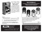
3T EXPLODED VIEW
Page 44 of 63
Effective Date: 6/11/2012
3T Spare Parts Listing
REF
001
002
003
004
005
006
007
008
009
010
011
012
014
015
016
017
018
019
020
021
022
023
024
025
026
027
028
029
030
DESCRIPTION
Nut, SS 7/16”
Impeller, Stud 7/16”
Grease Fitting
Pump Casing
Safety Washer
Screw, SS, Pump Casing
Mechanical Seal Assembly
Impeller Key
Impeller
Washer, Impeller
Locknut, Impeller
Tye Rod, SS
Nut, Bronze Knob
Stud
Gasket, Discharge
Discharge Port, NPT
Nut
O-Ring, Plug
Plug
Stud
Nut
O-Ring, Volute
Volute
Wear Plate w/Screw, SS
Screw, SS for Wear Plate
O-Ring, Pump Cover
Pump Cover
Gasket, Flapper Assembly
Suction Port, NPT
PART NUMBER
Q14-3000-001
Q14-3000-002
Q14-TL003/0
Q14-3000-004
Q14-3000-005
Q14-3000-006
Q14-TL007-31
Q14-3000-008
Q14-3000-009
Q14-TL010/3
Q14-TL011/3
TL012/3
Q14-TL014/0
Q14-2000-015
Q14-3000-016
Q14-3000-017
Q14-2000-018
Q14-TL019/0
Q14-TL020/0
Q14-3000-021
Q14-3000-022
Q14-3000-023
Q14-3000-024
Q14-3000-025
Q14-TL026/0
Q14-3000-027
Q14-3000-028
Q14-3000-029
Q14-3000-030
Page 45 of 63
Effective Date: 6/11/2012
Pump performance Curve
Pump End: 3T
Used on Model: 3T
Pump Ratings:
Maximum Impeller Speed: 3,600 rpm
Test Conditions:
Fluid: Water
S.G.: 1.0
Altitude: Sea Level (1 Atmosphere)
Temperature: 68°F (20°C)
Viscosity: 31.5 SSU
NOTES: Refer to Thompson Unit Specification Sheets for maximum and minimum operating speeds for the particular driver.
Tests were conducted according to Hydraulic Institute ANSI/HI 1.6 – 1994 Standards.
Page 46 of 63
Effective Date: 6/11/2012
TORQUE REFERENCE CHART
Bolt Size
Inches
¼ - 20
5
/16 – 18
3
/8 – 16
7
/16 – 14
½ - 13
9
/16 – 12
5
/8 – 11
¾ - 10
7
/8 – 9
1–8
SAE
0–1–2
6 ft-lbf
12 ft-lbf
20 ft-lbf
32 ft-lbf
47 ft-lbf
69 ft-lbf
96 ft-lbf
155 ft-lbf
206 ft-lbf
310 ft-lbf
SAE
Grade 5
10 ft-lbf
19 ft-lbf
33 ft-lbf
54 ft-lbf
78 ft-lbf
114 ft-lbf
154 ft-lbf
257 ft-lbf
382 ft-lbf
587 ft-lbf
Size
Stainless Steel Lockscrew
.38 – 16 UNC
20 ft-lbf
.50 – 13 UNC
40 ft-lbf
.62 – 11 UNC
90 ft-lbf
.75 – 10 UNC
135 ft-lbf
1.00 – 8 UNC
265 ft-lbf
SAE
Grade 8
14 ft-lbf
29 ft-lbf
47 ft-lbf
78 ft-lbf
119 ft-lbf
169 ft-lbf
230 ft-lbf
380 ft-lbf
600 ft-lbf
700 ft-lbf
Page 47 of 63
Effective Date: 6/11/2012
SAFETY ALERT SYMBOL
This Safety Alert Symbol means ATTENTION is involved.
The Safety Alert Symbol identifies important safety messages on machines, safety signs, in manuals,
or elsewhere. When you see this symbol, be alert to the possibility of personal injury or death. Follow
the instructions in the safety message.
Why is SAFETY important to YOU?
3 BIG REASONS
• Accidents KILL or DISABLE
• Accidents COST
• Accidents CAN BE AVOIDED
NOTICE OF COPYRIGHT PROTECTION
AEM Safety Manuals are protected as a copy righted work with ownership duly registered with the Copyright Office,
Washington, D.C. Any reproduction, translation, decompiling or other use of an AEM Safety Manual., or portion thereof, or
the creation of derivative works based on an AEM Safety Manual, without the prior written approval of AEM is expressly
prohibited. Copyright infringement can result in civil and criminal sanctions, damages and other penalties being imposed.
Copyright © 2004 – Association of Equipment Manufacturers
Page 48 of 63
Effective Date: 6/11/2012
FOREWARD
This safety manual is intended to point out some of the basic situations
which may be encountered during the normal operation and maintenance
of your equipment, and to suggest possible ways of dealing with these
conditions.
Additional precautions may be necessary, depending on application, pump
type, configuration and attachments used, conditions at the work-site or in
the maintenance area. The manufacturer has no direct control over pump
application, operation, inspection, lubrication or maintenance. Therefore, it
is your responsibility to use good, safe, practices in these areas.
The information provided in this manual supplements the specific
information about your pump that is contained in the manufacturer’s
manual(s). Other information which may affect the safe operation of your
pump may be contained on safety signs, decals, markings, insurance
requirements, employer’s safety programs, safety codes, local,
state/provincial and federal laws, rules and regulations, contracts,
agreements and warranties.
It is your responsibility to read and understand this safety manual and the
manufacturer’s manual(s) before operating your pump. This safety manual
takes you step-by-step through your working day. If you do not understand
any of this information, or if errors or contradictions seem to exist, consult
with your supervisor before operating your pump.
IMPORTANT: If you do not have the manufacturer’s manual(s) for
your particular pump, get a replacement manual from your employer,
equipment dealer, or manufacturer of your pump. Keep this safety
manual and the manufacturer’s manual(s) with your pump.
Unauthorized modifications of pumps create hazards. Pumps must not be
modified or altered unless prior approval is obtained from the manufacturer.
DO NOT PUMP VOLATILE/FLAMMABLE OR CAUSTIC/CORROSIVE
LIQUIDS. REFER TO THE OWNER’S MANUAL OR CONSULT WITH
THE MANUFACTURER FOR THE PROPER PUMP MATERIALS IF YOU
ARE TO PUMP HAZARDOUS CAUSTIC/CORROSIVE LIQUIDS.
FOLLOW A SAFETY PROGRAM
Know the meaning of all hand signals, signal flags, signs and markings.
Know the traffic rules used at the work site. Know who the signal man is;
watch and obey his signals.
Know where the fire extinguishers and first aid kits are kept and how to
use them. Know where to get proper aid and assistance when needed.
Use common sense to avoid accidents. If an accident does occur, be
prepared to react to it quickly and effectively. NEVER PANIC.
Remember that YOU are the key to safety. Good safety practices not
only protect you but also protect the people around you. Study this
manual and the manufacturer’s manual(s) for your specific pump. Make
them a working part of your
safety program. Keep in mind
that this safety manual is written
for only this type of equipment.
Practice all other usual and
customary safe working precautions,
and above all (FIG 1.).
FOLLOW A SAFETY PROGRAM
KNOW WHAT IT IS?
Consult your supervisor for specific
Instructions and personal safety equipment required.
For instance, you may need:
Hard Hat
Safety Shoes
Eye Protection
Respirators
Heavy Gloves
Reflector Vests
Hearing Protection
Face Protection
Back Supports
Other job related specific items
Do not wear loose clothing or any accessory – flopping cuffs, untied
show-laces, dangling neckties and scarves, rings, wrist watches, or
other jewelry – that can catch on protruding or moving parts or controls.
Long hair should be securely bound to prevent entanglement with
moving parts. (FIG 3)
KNOW THE RULES
Each employer is concerned about safety. Safe operation and proper
maintenance of your pump can prevent accidents. KNOW the rules – LIVE
by them. (FIG 1.)
When starting work at a new site, check with the designated safety
coordinator for specific safety instructions. DON’T LEARN SAFETY THE
HARD WAY.
Page 49 of 63
Effective Date: 6/11/2012
BE ALERT!
EXHAUST FUMES
Know where to get assistance. Know how to use a first aid kit and fire
extinguisher or fire suppression system. (FIG 4)
Engine exhaust fumes can cause sickness or death. If it is necessary to
run an engine in an enclosed area, remove the exhaust fumes from the
area with an exhaust pipe extension. If you do not have an exhaust pipe
extension, be positive the area is adequately ventilated.
BE AWARE!
Take advantage of training programs offered.
Safety programs should require that one person at each jobsite be
assigned the overall responsibility and authority for safety. Know who
the person it, and COMMUNICATE with the.
Know what the jobsite rules are, and FOLLOW THE RULES. Be safety
conscious, responsible and reliable. Think about safety BEFORE
something happens.
BE CAREFUL!
Human error is caused by many factors: carelessness, fatigue, overload,
preoccupation, incompatibility between operator and the equipment,
drugs, and alcohol to name a few. Damage to the equipment can be
fixed in a short period of time, but injury, or death has a lasting effect.
For your safety and safety of others, encourage your fellow workers to
act within safety rules.
HEAVY PARTS
Handle tools and heavy parts sensibly – with regard for yourself and
other persons. Lower items – don’t throw or drop them.
ALWAYS use proper hoisting equipment for lifting heavy loads.
ALWAYS. Use a back brace when lifting by hand.
PERFORM MAINTENANCE SAFELY
CLOTHING AND PERSONAL PROTECTIVE ITEMS
ALWAYS wear appropriate safety glasses, goggles, or face shield when
working. (FIG 2) Proper eye protection can keep flying particles from
grinding, drilling or hammering operations, or fluids such as fuel,
solvents, lubricants and brake fluids from damaging your eyes. Normal
glasses do NOT provide adequate protection.
ALWAYS wear a hard hat and safety shoes. (FIG 2) ALWAYS wear
hearing protectors when exposed to high noise levels for extended
periods. ALWAYS wear a respirator when painting or exposed to dusty
conditions. ALWAYS keep your pockets free of loose objects, which can
fall out and drop into machinery. (FIG 5) Heavy gloves should be worn
Page 50 of 63
Effective Date: 6/11/2012
FIRE PREVENTION
Whenever possible use a non-flammable solvent to clean parts. Do not
use gasoline or other fluids that give harmful vapors. If flammable fluids,
such as gasoline or diesel fuel, must be used, extinguish open flames or
sparks and DO NOT smoke.
Store dangerous fluids in a suitable place, in approved containers, which
are clearly marked. NEVER smoke in areas where flammable fluids are
used or stored. (FIG 7)
Use proper non-flammable cleaning solvents. Follow solvent
manufacturer’s instructions for use.
WORK SAFELY – PUMPS IN GENERAL
PREPARE FOR SAFE OPERATION
LEARN TO BE SAFE
NEVER operate a pump which is new to you without first being
instructed in its proper operation. READ the operator’s manual. If one
has not been provided. GET ONE AND STUDY IT BEFORE
OPERATING THE PUMP.
Know the meaning of all identification symbols on your control and
gauges. (FIG 8) Know the location of the emergency shut-down control if
the machine is so equipped.
Before attempting to operate the pump, know the capabilities and
limitations of the pump. Familiarize yourself with controls and
instruments – their locations and functions.
Keep hands, levers and knobs clean of oil or grease to prevent slipping.
Carefully read and follow the instructions on all safety signs and decals
on the pump. Keep safety signs in good condition. Replace missing or
SAFE WORKING PROCEDURES
USE COMMON SENSE! Most accidents can be avoided by using
common sense and concentrating on the job to be done.
ONLY EXPERIENCED AND QUALIFIED personnel should install and
operate pump equipment.
KNOW THE PROPER starting procedure for your equipment. Follow
the manufacturer’s operation manual to the letter.
DO NOT operate a pump without all guards and shields in place. If
OSHA required guards are damaged or misplaced, contact the
manufacturer for replacement.
When lifting pump use only lifting equipment in good repair and with
adequate capacity. Follow manufacturer’s lifting recommendation.
Check all lubricant levels before pump installation in accordance with
manufacturer’s maintenance programs.
Keep hands and feet clear of moving parts. DO NOT stick fingers into
a pump when in operation. Check suction strainer and hose regularly for
proper submergence and to be sure it is free of obstructions.
NEVER operate a self-priming pump unless the volute is filled with
liquid. The pump will not prime when dry.
CHECK IT OUT!
Know what safety devices your machine is equipped with and see that
each item is securely in place and in operating condition. (FIG 9)
For example:
Drawbar Coupling Chains and Pins
Alarms and Warning Lamps
Reflectors
Guards and Shields
Drain Covers, Plugs and Caps
Shut-Down Devices
Leveling Jacks
Pressure Relief Devices
Lifting Devices
NEVER START OR OPERATE A PUMP
KNOWN OR SUSPECTED TO BE
DEFECTIVE OR MALFUNCTIONING
If your daily check uncovers any items that need attention – repair,
replacement, or adjustment – report them promptly. The most minor
malfunction could be the result of more serious trouble – or can cause it,
if pump is operated. When in doubt, attach an OSHA Lockout/Tagout
device tag to the control panel to disconnected electrical power supply at
breaker, on electrically driven pumps and disconnect the battery and/or
spark plug wire on engine driven pumps.
PUMP only liquids for which the pump has been designed to handle.
DO NOT pump flammable, corrosive or caustic materials unless the
pump and piping are explicitly designed for that purpose.
A pump should not be operated against a closed valve or other no
flow conditions. Refer to the pump manufacturer’s recommended
practice for start-up, operation and shut-down procedures. DO NOT
close down or restrict a discharging hose. Be careful of discharge hose
whipping under pressure.
MAKE CERTAIN that whatever is to be connected to the pump is not
subjected to pressures greater than those given in the manufacturer’s
instructions.
MAKE CERTAIN all connections are securely made and hoses
under pressure are secured, with appropriate safety devices, to
prevent whipping.
BE AWARE OF LIGHTNING. Stay clear of the pumping equipment
during electrical storms. It can attract lightning. (FIG 10)
OVERHEATING PRECAUTIONS
Overhead pumps can cause severe damage to the equipment and
can cause severe physical burns and injury.
Operating a pump with the suction and/or discharge valve closed is
a principal cause of overheating. Approach cautiously any pump that has
been in operation.
Page 51 of 63
Effective Date: 6/11/2012
DO NOT remove hoses from a pump until the system is properly cooled
to ambient temperature.
•
If an unsafe condition cannot be remedies immediately, notify
your supervisor and tagout/lockout the pump on the start switch
and/or appropriate, prominent location. (FIG 11)
DO NOT remove the cover plate or drain plugs from any overheated
pump. Allow the pump to cool. Check pump temperature before opening
fill port or drain plug.
If overheating of the pump casing occurs:
•
STOP the pump immediately
•
Allow the equipment to cool completely
•
Slowly and cautiously vent the pump
•
Refer to the manufacturer’s instruction manual before restarting
the unit
•
Remove hoses carefully. Heated water can be in hoses and static
head produces pressure.
WORK SAFELY – ENGINE DRIVEN PUMPS
Do not jump start engine battery.
When operating internal combustion engines in an enclosed area,
always make provisions to pipe exhaust fumes to the outside.
EXHAUST FUMES CAN KILL. Do not operate engine driven pump
equipment in a confined or enclosed space without adequate ventilation.
Exhaust gases are odorless and deadly poison.
BEFORE STARTING
Check the pump thoroughly at delivery for any shipping damage.
Locate the pump in an accessible location, as close to the liquid as
possible.
Secure the pump after it is placed in its intended operating position so it
does not tip, roll, slide or fall.
DO NOT TOUCH: The exhaust system components get very hot and
stay hot for some time after shutting the engine off.
Follow engine manufacturer’s instructions explicitly on hand cranking.
Do not shut down high head pumps quickly:
1. Throttle back slowly
2. Open by-pass line
3. Should have a check valve
4. Slowly close gate valve on discharge if so equipped
IMMEDIATELY ON STARTING THE PUMP
Check for fuel, oil and hydraulic fluid leaks, worn and damaged
hoses/lines or power cables.
Observe gauges, instruments and warning lights to ensure that they are
functioning and their readings are within the normal operating range.
Refueling:
•
•
•
•
•
•
Be sure the immediate work area is safe for operation
Operate control; make certain all operate properly and “feel” right.
Accustom yourself to the “feel” of the equipment
Listen for any unusual noises, smell for any unusual odors; look for
any signs of trouble
Be sure to open all manual valves slowly to prevent WATER
HAMMER
Check all warning and safety devices and indicators.
If safety-related defects or malfunctions are detected, SHUT
DOWN the equipment. Correct the problem, or notify your
supervisor. DO NOT OPERATE EQUIPMENT WITH DEFECTS
Page 52 of 63
Effective Date: 6/11/2012
When refueling, the following precautions must be followed:
•
Add fuel of proper type and grade, only when the pump is not
running and engine is cool
•
Fuel in well ventilated area
•
Turn off all electrical switches
•
Keep lighted smoking materials, flames or spark producing devices
at a safe distance while refueling
•
Keep fuel nozzle in contact with tank being filled, or provide a
ground to prevent static sparks from igniting fuel
•
•
•
•
Do not spill fuel on hot surfaces
Clean up spillage immediately
Do not start engine until fuel cap is secured to the fuel tank
Always make sure that fuel is being put in the fuel tank, motor oil
in the proper location and hydraulic oil into hydraulic oil reservoirs
Maintenance and Repair:
WORK SAFELY – ELECTRIC MOTOR
DRIVEN PUMPS
Follow motor manufacturer’s recommended maintenance and operation
instructions.
All installations, operations and maintenance should be in
accordance with pump and engine manufacturer’s recommended
operation and maintenance program. These manuals should be kept
available with the equipment.
If circuit breaker or fuse is stripped, examine the system for the
problem before restarting pump.
Maintenance work can be hazardous if not done in a careful manner. All
personnel should realize the hazards and strictly follow safe practices.
NEVER operate a pump with a plug-in type power cord without a ground
fault circuit interrupter.
NEVER perform any work on the equipment unless authorized to do so.
NEVER use cords with frayed, cut or brittle insulation. Check the cord on
the pump for nicks in the insulation and for sound connections to the
ground fault interrupter plug and motor.
BEFORE ANY maintenance work is to be done, a LOCKOUT/TAGOUT
standard device and procedure should be implemented. Prior to removal
of LOCKOUT/TAGOUT, the equipment must be fully operational and all
personnel accounted for. Except in cases of emergency, the removal of
the LOCKOUT/TAGOUT should be done ONLY by the initiating person
prior to the return to start-up (see Section 3, Page 5, FIG 11)
NEVER use the power cord to aid lifting the pump.
NEVER let extension cords or the plug connections lay in water. Locate
the pump so that the cord cannot fall into any water or be submerged by
rising water, unless the pump is designated for such use.
NEVER handle energized power cords with wet hands
BEFORE doing any major work, disconnect the ignition and battery if so
equipped. Always replace safety devices removed during service or
repair before returning pump to operation.
Battery Servicing:
•
•
•
•
•
Always wear safety glasses and gloves when servicing or working
with batteries.
Before servicing battery, turn off electrical systems, then
disconnect ground terminal clamp. Before installing a battery, turn
off electrical equipment, then connect the battery ground clamp
last.
Maintain electrolyte at the recommended level. Check level
frequently. Add distilled water to batteries only when starting up,
never when shutting down.
Use a flashlight to check level. NEVER use a flame
Do not short across battery terminals – the spark could ignite the
battery gases.
Battery acids will burn skin, eat holes in clothing, and can cause
blindness if splashed in eyes.
If you spill acid on yourself flush skin immediately with lots of
water. Apply baking soda to help neutralize the acid. If acid gets
into the eyes, flush immediately with large amounts of water and
seek proper medical treatment immediately.
MOTOR OVERLOAD: do not exceed the manufacturer’s
recommendation for maximum lift or discharge head. See
manufacturer’s published curve for proper sizing of motors. A misapplied
motor can overheat.
Pump Maintenance and Repair:
MAKE SURE the pump is disconnected from the power source or the
appropriate circuits are dead and OSHA Lockout/Tagout is applied
before doing any maintenance or repair work on the pump.
Maintenance work can be hazardous if not done in a careful manner. All
personnel should realize the hazards and strictly follow safe practices.
NEVER perform any work on the equipment unless authorized to do so.
(FIG 11) Before performing any maintenance or repair work, consult the
manufacturer’s instruction manual for recommended procedures.
Pumps with float switches or other automatic devices can start without
warning if not properly locked out.
BEFORE ANY maintenance work is to be done, a LOCKOUT/TAGOUT
standard device and procedure should be implemented. Prior to removal
of LOCKOUT/TAGOUT, the equipment must be fully operational and all
personnel accounted for. Except in cases of emergency, the removal of
the LOCKOUT/TAGOUT should be done ONLY by the initiating person
prior to the return to start-up.
ALWAYS replace safety devices removed during the service or repair
before returning pump to operation.
NEVER use the power cord to aid in lifting the pump.
Page 53 of 63
Effective Date: 6/11/2012
Sizing Extension Cords:
Use the following chart to select the correct size extension cord to
prevent excessive amperage draw or voltage drop, which would cause
the motor to overheat. Cables that are too long or coiled can cause a
voltage drop. Be aware that strong sunlight can cause a voltage drop.
Amperes
6
8
10
12
14
16
Wire Gauge and Cord Length
(in feet)
50
100
150
16
16
14
16
14
12
16
14
12
14
14
12
14
12
10
12
12
10
SAFETY MANUAL
Pump Maintenance and Repair:
MAKE SURE the pump is disconnected from the power source or the
appropriate circuits are dead and OSHA Lockout/Tagout is applied
before doing any maintenance or repair work on the unit.
Maintenance work can be hazardous if not done in a careful manner. All
personnel should realize the hazards and strictly follow safe practices.
SAFE WORKING PROCEDURES
ALLOW only qualifies personnel to INSTALL, WIRE and OPERATE
submersible pumps
NEVER perform any work on the equipment unless authorized to do so.
Before performing any maintenance or repair work, consult the
manufacturer’s instruction manual for recommended procedures.
ALWAYS ground the pump.
BEFORE ANY maintenance work is to be done, a LOCKOUT/TAGOUT
standard device and procedure should be implemented. Prior to removal
of LOCKOUT/TAGOUT, the equipment must be fully operational and all
personnel accounted for. Except in cases of emergency, the removal of
the LOCKOUT/TAGOUT should be done ONLY by the initiating person
prior to the return to start-up.
Make certain to connect the pump to the right phase and voltage.
Check oil level ONLY when pump is cool.
DO NOT run the pump if voltage is not within limits. Make all electrical
installations in accordance with National Electric Code, State and Local
electric codes.
USE ONLY recommended oil per manufacturer’s recommendation.
Whenever electricity is present there is the possibility of electrocution.
NEVER use a pump/motor in an explosive atmosphere if it is not
exclusively designed for that application.
Mount electrical control box in a vertical position protected from the
elements.
NEVER attempt to use the power cord or hydraulic hoses as a lifting or
lowering device for submersibles. Attach a lifting cable to the
manufacturer’s recommended attachment point on the pump for
lowering and lifting the pump. (FIG 12)
NEVER position the pump directly on a soft, loose bottom. To attain
maximum capacity and prevent excessive wear, position the pump so it
will not burrow itself into sand or clay. Stand the pump in a plank, a bed
of coarse gravel, within a perforated container, on a suitable flotation
device, or retain it hanging freely by a lifting cable. (FIG 13)
INSPECT ELECTRICAL WIRING for worn or damaged insulation.
INSTALL new wiring if wires are damaged. After repairs are made,
clean the equipment before putting the pump back into position.
FINAL WORD TO USER
Remember that YOU are the key to safety. Good safety practices not
only protect you but also protect the people around you.
You have read this safety manual and the manufacturer’s manual(s) for
your specific pump. Make them a working part of your safety program.
Keep in mind that this safety manual is written for this type of equipment.
Practice all other usual and customary safe working precautions, and
above all –
REMEMBER
SAFETY IS UP TO YOU
YOU CAN PREVENT SERIOUS
INJURY OR DEATH
Page 54 of 63
Effective Date: 6/11/2012
REFERENCES
The following is a partial list of referenced material on safe operating practices:
U.S. Department of Labor publishes safety and health regulations and standards under the authority of
the Occupational Safety and Health Act for the general construction and mining industries.
U.S. Department of Labor
Washington, DC 20210
NFPA – National Fire Protection Association
P.O. Box 9101
1 Battery March Park
Quincy, MA 02269-0101
SAE – Society of Automotive Engineers, Inc.
400 Commonwealth Drive
Warrendale, PA 15096
Publishes a list, “Operator Precautions” SAE J153 May 87.
AEM – Association of Equipment Manufacturers
111 East Wisconsin Avenue
Milwaukee, WI 53202
Page 55 of 63
Effective Date: 6/11/2012
CONDITIONS OF SALE
This LIMITED WARRANTY is extended only to the original consumer/purchaser of products manufactured by Thompson Pump & Mfg., Co., Inc.,
P.O. Box 291370, Port Orange, Florida, 32129-1370. Telephone number: 386-767-7310.
Thompson Pump & Mfg., Co., Inc, hereinafter referred to as “Thompson”, warrants the products it manufactures to be free of defects in materials
and workmanship. The warranty extends only to the original consumer/purchaser, hereinafter referred to as “Consumer”, and commences on the
date of sale to said Consumer and remains in effect for a period of twelve (12) months.
THIS WARRANTY DOES NOT COVER:
a. Adjustment or replacement of maintenance items and wear parts, such as but not limited to, seals, bearings, lubrication and filters.
b. Any work performed to correct malfunction caused by misuse, negligence or disregard of Thompson’s written instructions concerning
installation, operation and maintenance of its products.
c. Additional service work performed above that which is required to satisfy warranty requirements.
d. Transportation charges, haul-out, travel time, loss of use, or other consequential charge or damage.
e. Any damage caused by sand or abrasive materials, chemical deposits, corrosion, hazardous waste or material, acts of God or other outside
forces beyond the control of Thompson.
f. Engines, electric motors and other items not of our manufacture. Warranty on those items, if any, is the warranty of the manufacturer of such
items.
g. Repairs or replacement made without authorization from Thompson or repairs made other than at a service facility designated by Thompson.
h. Delivery schedules are not covered by any warranty terms, and all dates given are approximate and subject to change without notice.
In the event of any breach of the warranty, the original Consumer must deliver or ship the defective unit or parts, freight prepaid, to the factory or
any of the Thompson authorized parts and service centers, providing prior permission is obtained from the factory. Thompson agrees that it will
replace or repair (at our option) any such unit or parts where the defect results from a breach of its warranty without charge to the original
Consumer, provided said defect occurred within the warranty period. Thompson or the authorized service repair centers will not be responsible for
the cost of the units or parts and the shipment of said unit or parts to or from Thompson’s plant or service centers.
Thompson’s warranty obligation with regard to equipment not of its own manufacture is limited to the warranty actually extended to Thompson by
its suppliers. Should a failure of such motor or engine occur during the warranty period, the original Consumer must notify Thompson Pump &
Mfg., Co., Inc., Port Orange, Florida and follow the instructions given. THIS WARRANTY DOES NOT COVER REPAIRS OR REPLACEMENT
MADE WITHOUT NOTIFICATION TO THOMPSON PUMP & MFG., CO., INC.
THIS WARRANTY IS EXPRESSLY IN LIEU OF ANY OTHER EXPRESS OR IMPLIED WARRANTIES INCLUDING ANY IMPLIED WARRANTY
OF MERCHANTABILITY OR FITNESS FOR A PARTICULAR PURPOSE AND OF ANY OTHER OBLIGATION ON THE PART OF THE SELLER.
NO AGENT, EMPLOYEE OR REPRESENTATIVE OF THE SELLER HAS ANY AUTHORITY TO BIND THE SELLER TO ANY AFFIRMATIONS,
REPRESENTATION OR WARRANTY CONCERNING THE PRODUCT SOLD UNDER THIS WARRANTY. THERE ARE NO WARRANTIES
WHICH EXTEND BEYOND THE DESCRIPTION ON THE FACE HEREOF. IMPLIED WARRANTIES, WHEN APPLICABLE, SHALL COMMENCE
UPON THE SAME DATE AS THE EXPRESS WARRANTY ABOVE AND SHALL, EXCEPT FOR WARRANTIES OF TITLE, EXTEND ONLY FOR
THE DURATION OF THE WARRANTY.
Some states do not allow limitations on how long the implied warranty lasts, so the above limitations may not apply to you. The only remedy
provided to you under an applicable implied warranty or the express warranty shall be the remedy provided under the express warranty, subject to
the terms and conditions contained therein.
Thompson Pump & Mfg., Co., Inc., shall not be liable for incidental or consequential loses and damages under the express warranty, any
applicable implied warranty or claim for negligence, except to the extent that this limitation is found to unenforceable under applicable state law.
Some states do not allow the exclusion or limitation of incidental or consequential damages, so the above limitation or exclusion may not apply to
you.
This warranty gives you specific legal rights, and you may also have other rights, which vary from state to state.
For more information, contact the Thompson Pump Service Department at (800) 767-7310
Page 56 of 63
Effective Date: 6/11/2012
Warranty Policy Definitions
Warranty – a warranty is defined as a guarantee, written by the manufacturer, which assures the integrity of a product in respect to its
performance, reliability, and durability during specified period of time (see Limited Warranty). Warranty is intended to protect the consumer from a
faulty product. However, it should be clearly understood that the bilateral communication associated with warranty provides the manufacturer with
the necessary information required to institute design, manufacturing, or quality control improvements, which are intended to result in an improved
product line.
Material Defect – a material defect is an inherent flaw in the material, often undetectable until its flaw causes a failure due to the part being unable
to perform its normal function. Examples of a material defect would include incorrect raw material or casting defects.
Defective Workmanship – relates to the improper assembly of the pump, or any of its sub-assemblies, or to the dimensional incorrectness of any
of the components. Examples of defective workmanship would include misalignment, incorrect bolt tightening, incorrect assembly, or the absence
of a correct or required component.
Sales Policy or Goodwill Adjustments - from time to time the company will issue Sales Policy adjustments as a settlement, which Thompson may
make, as its option, which are beyond the scope of the Thompson Limited Warranty policies and which are not necessarily related to either a
material defect or improper workmanship. This type of settlement is generally regarded as a public relations instrument.
Warranty Approval / Rejection
In all cases, Thompson Pump reserves the right to approve, reject or partially approve a warranty claim. The Thompson Warranty Department will
provide to the best of its ability a failure analysis decision within 30 days of receipt of the completed claim. It must be understood that the
Thompson Pump Warranty Department will evaluate and assess all warranty claims. All warranty approvals will be based upon our standard
warranty policy.
A detailed Warranty Claim Form must be submitted to the Thompson Pump Warranty department within 10 days after the failure occurs. The
Warranty Claim Form must be complete and accurate when it is submitted to Thompson Pump.
All damaged parts must be retained and returned to Thompson Pump if and when requested.
In cases where the full or partial amount of a warranty claim is approved a copy of the approved warranty claim will be returned with an evaluation
letter and a credit memo for the appropriate parts, labor and mileage.
Labor will be reimbursed to the distributor for labor hours in accordance with Thompson Pump’s established repair policies set by the Warranty
Department. Thompson Pump will reimburse the distributor at a rate for a single mechanic equal to 75% of the distributors straight time (flat) shop
rate not to exceed $ 45.00 per hour.
Should a warranty repair take place in the field, Thompson Pump will reimburse the distributor for labor costs as noted above and mileage. The
distributor must notify Thompson Pump prior to repairing the equipment at which time the Thompson Warranty Department will authorize in
writing, the field repair. Thompson Pump will reimburse the distributor at a rate of $ 1.00 per round trip mile, which includes the labor costs of the
driver/mechanic.
Thompson Pump will provide replacement parts to affect a warranty repair at no charge to the Distributor or the Consumer.
If the parts used for a warranty repair are supplied from the Distributor’s stock, Thompson Pump will provide the replacement parts at no charge or
a credit will be issued to the Distributor for the Distributor’s normal cost plus an additional 10% discount allowed.
Thompson Pump does not warrant equipment or parts that are not of its manufacture but which are required in the production of a complete pump
unit or accessory and any such claims must be filed with the appropriate manufacturer. Examples of equipment or parts not of Thompson Pump’s
manufacture are, but are not limited to, engines, air compressors, vacuum pumps, drive couplings, wheels and tires, and axles.
All parts for rejected warranty claims will be invoiced at standard list price less any applicable discount.
For more information, contact the Thompson Pump Service Department at (800) 767-7310
Effective: 11/15/02 jjf
Page 57 of 63
Effective Date: 6/11/2012
Bill of Materials
QTY
PART NUMBER
DESCRIPTION
1
1
1
1
1
1
0.125
1
1
4
2
2
1
1
1
1
1
1
1
1
2
2
2
6
6
8
4
4
6
C98-5487-001
C98-LABL-016
C98-LABL-200
C98-LABL-036
C98-LABEL-01
C98-LABL-018
C89-DUP-AK
M54-BC-POS-23T
M54-BC-NEG-23T
H61-0001-017
HA-HCS-25C-100-5Z
HA-NYN-25C-2Z
M54-9U1L
NAME PLATE, TPM SER.NO., SILVER/BLUE
LABEL, DIESEL FUEL ONLY
LABEL, OPERATOR'S LIABILITY NOTICE
LABEL, WATER DRAIN 1 X 2"
LABEL, DO NOT PUMP VOLATILE, FLAMMABLE,
LABEL, FILL WITH WATER BEFORE USING
PAINT, YELLOW LEAD FREE #224AK
CABLE, RED BATTERY, 2T/3T,
CABLE, BATTERY, 2T/3T, NEG
WASHER, FLAT 1/4 SAE
HEXHEAD CAPSCREW 1/4-20X1 ZINC
LOCK NUT, 1/4"-20 NYLOCK USS ZINC
BATTERY, 12 VOLT,320 AMP,CAP. SMALL
ENGINE, DIESEL
ADAPTOR, PILOT 3T/15LD350
SLEEVE, SHAFT 3T/15LD350
NUT, JAM, 3/8" SAE, S.S.
STUD, IMPELLER, SS, FOR 3T/4T
3T-DL-15LD SQ. TUBING FRAME
PUMP END, 3" TRASHLIB FOR 8.5HP
NIPPLE, 3" X CLOSE NPT FACED
HHCS, 10M-1.5-25M
WASHER, LOCK 10M
WASHER, LOCK 8M
NUT, HEX 8M X 1.25
WASHER, FLAT 3/8 SAE
HHCS, 3/8x1-1/4 GR 5 PLT NC
LOCK NUT, 3/8"-16 NYLOCK
ISOLATOR, FOR HONDA ENGINE
Q14-3000-TS3002
Q14-3000-TS3001
Q14-TL001/32
Q14-TL002/32
K08-TW0829-C1
P14-3TL8.5
W67-0001-089F
H62-0001-056
H62-0001-019
H62-0001-018
H62-0001-003
H61-0001-019
H60-0001-056
HA-NYN-375C-2Z
F38-68325-YB9-000
Page 58 of 63
Effective Date: 6/11/2012
Parts Order Form
IMPORTANT!
To expedite orders and lessen mistakes, it is recommended that a fax be sent with the
following information:
Name: ______ ______________________________ Title: _______________________ _
Company:_________________________________________________________________
Address: _____________________________________________________________ ____
City: ______________________________ State: ___ _______Zip:___________________
Phone: (_______)____________________
Fax: (_______)___________________ ____
E-mail address: ____________________________________________________________
Unit Serial Number: ___________________________________ {VERY IMPORTANT}
List of parts by part number, description, and quantity
If the part numbers (s) are unknown, please give as full a description as possible, so that we
may expedite your shipment.
FAX NUMBER:
386-761-4498
e-mail: [email protected]
Phone Number (Toll Free): 888-421-7185
Gary Peake
Parts Sales
Ext. 4161
Nellie Morris
Parts Sales
Ext. 4172
Steve Seymour
Parts Sales
Ext. 4160
4620 City Center Dr. Port Orange, Fl 32129-1370 Phone: 800-767-7310
$20.00 MINIMUM ORDER
Page 59 of 63
Effective Date: 6/11/2012
Manual Registration Form
IMPORTANT!
Please provide the information requested below so that we can automatically update manual
information as revisions occur.
Name: ______ _____________________________ Title: ________________________ _
Company:_________________________________________________________________
Address: __________________________________________________________________
City: _______________________________ State: ___ _______Zip:__________________
Phone: (_______)____________________
Fax: (_______)___________________ ____
Unit Serial Number: ______________
Type of Pump: ___________________ Serial Number _____________
E-mail address: _________________________________________________________________________
Revised documents will be e-mailed when available. At Thompson Pump’s discretion, revised documents will be batched and distributed on CD.
Please return to Thompson Pump, Attention: Engineering Department.
Page 60 of 63
Effective Date: 6/11/2012
Thompson Pump & Manufacturing Co., Inc.
4620 CITY CENTER DRIVE
P.O. BOX 291370
PORT ORANGE, FLORIDA, USA, 32129
www.thompsonpump.com
MAIN OFFICE:
PHONE: (800) 767-7310
FAX: (386) 767-4753
PARTS DEPARTMENT:
Jerry Tarnow, Parts Sales Mgr.
SERVICE DEPARTMENT:
Bill Crooms, National Service Mgr.
PHONE: (888) 421-7185
(386) 944-4110
[email protected]
PHONE: (800) 761-7310
(386) 944-4139
FAX: (386) 761-4498
FAX: (386) 767-4753
[email protected]
FT. MYERS SERVICE CENTER:
5491 Division Drive, Ft. Myers, FL 33905
TOLL FREE:
(877) 689-7634
PHONE:
(239) 690-0600
FAX:
(239) 690-0904
WEST COAST OFFICE:
504 South 70th Street, Kansas City, KS 66111
PHONE:
(816) 935-5311
FAX:
(913) 788-5568
NEW ENGLAND BRANCH:
21 Arnold Farm Rd, W. Greenwich, RI 02817
PHONE:
(401) 397-4950
FAX:
(401) 397-4980
JACKSONVILLE SERVICE CENTER:
6743 Greenland Industrial Blvd
Jacksonville, FL 32258
TOLL FREE:
(800) 767-7305
PHONE:
(904) 292-4883
FAX:
(904) 262-5183
SAVANNAH SERVICE CENTER:
125 Westside Blvd, Pooler, GA 31322
TOLL FREE:
(800) 767-8507
PHONE:
(912) 330-0233
FAX:
(912) 330-0280
CHARLESTON SERVICE CENTER:
120 Jed Park Place, Summerville, SC 29483
TOLL FREE:
(800) 767-7309
PHONE:
(843) 879-0393
FAX:
(843) 879-0397
ORLANDO SERVICE CENTER:
706 W. Landstreet Road, Orlando, FL 32824
TOLL FREE:
(800) 767-7304
PHONE:
(407) 812-4007
FAX:
(407) 812-4030
BATON ROUGE SERVICE CENTER:
18394 Tom Dr, Hammond, LA 70403
TOLL FREE:
(800) 510-5649
PHONE:
(985) 321-0070
FAX:
(985) 321-0074
CHESAPEAKE VIRGINIA BRANCH:
1321 Victory Blvd., Chesapeake, VA 23323
TOLL FREE:
(800) 767-7307
PHONE:
(757) 485-4690
FAX:
(757) 485-4779
PANAMA CITY SERVICE CENTER:
1619 Florida Ave., Lynn Haven, FL 32444
PHONE:
(850) 277-0445
FAX:
(850) 277-0120
MARYLAND SERVICE CENTER:
38190 Old Stage Rd Unit A, Delmar DE 19940
PHONE:
(302) 907-0292
FAX:
(302) 907-0532
MYRTLE BEACH SERVICE CENTER:
157 Winyah Road, Conway, SC 29526
PHONE:
(843) 347-5532
FAX:
(843) 347-5542
PENSACOLA SERVICE CENTER:
3310 McLemore Drive, Pensacola, FL 32514
TOLL FREE:
(800) 767-7313
PHONE:
(850) 478-2833
FAX:
(850) 479-4349
KANSAS CITY BRANCH:
504 South 70th Street, Kansas City, KS 66111
PHONE:
(913) 788-2583
FAX:
(913) 788-5568
ATLANTA GEORGIA BRANCH:
1481 Dogwood Dr, Conyers GA 30012
PHONE:
(678) 382-0151
FAX:
(678) 382-0153
SARASOTA SERVICE CENTER:
6851 26th Court East, Sarasota, FL 34243
TOLL FREE:
(800) 767-7312
PHONE:
(941) 755-3177
FAX:
(941) 753-8618
JACKSON MISSISSIPPI BRANCH:
2110 Hwy 49 S., Florence, MS 39073
TOLL FREE:
(800) 767-7314
PHONE:
(601) 932-4916
FAX:
(601) 932-4918
BALTIMORE BRANCH:
7527 Montevideo Rd, Jessup, MD 20794
PHONE:
(410) 799-0451
FAX:
(410) 799-0454
WEST PALM BEACH SERVICE CENTER:
15935 Assembly Loop, Jupiter, FL 33479
TOLL FREE:
(800) 767-7311
PHONE:
(561) 624-7801
FAX:
(561) 624-7803
GOLDSBORO NORTH CAROLINA BRANCH:
2963 U.S. 13 North, Goldsboro, NC 27534
TOLL FREE:
(800) 767-7308
PHONE:
(919) 778-2743
FAX:
(919) 778-7335
Page 61 of 63
Effective Date: 6/11/2012
Page 62 of 63
Effective Date: 6/11/2012
Warranty Registration Form
IMPORTANT!
Please note that to receive warranty coverage, the pump unit must be registered for warranty upon
receipt by the owner. Please provide the information requested below.
Name: ______ _____________________________ Title: ________________________ _
Company:_________________________________________________________________
Address: __________________________________________________________________
City: _______________________________ State: ___ _______Zip:__________________
Phone: (_______)_________________
Fax: (_______) _________________ ____
DATE PURCHASED: ____________November
16, 2011_________
Unit Serial Number: 3T-DKW-xxx
Type of Pump: 3” Trash Pump
Serial Number ______________________
E-mail address:
____________________________________________________
Revised documents will be e-mailed when available. At Thompson Pump’s discretion, revised documents will be batched and distributed on CD.
PLEASE FILL IN FORM AND MAIL THIS WARRANTY REGISTRATION FORM UPON RECEIPT
MAIL TO: THOMPSON PUMP, P.O. BOX 291370, PORT ORANGE, FL, USA, 32129
ORDER#
Page 63 of 63
Effective Date: 6/11/2012