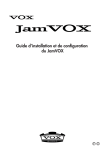
1
Decoder Firmware B1D-220-V3.03.07-AC User’s Manual i Table of Contents INTRODUCTION ____________________________________________________ 1 1.1 Minimum system requirements ______________________________________ 1 1.2 Preparation before setup ___________________________________________ 2 1.2.1 1.3 1.3.1 Setup your PC network ___________________________________________________ 2 Configuring the video Decoder ______________________________________ 6 Host Setting ____________________________________________________________ 8 1.3.2 WAN Setting ____________________________________________________________ 11 1.3.3 Connection Setting _____________________________________________________ 14 1.3.4 User Account Management _______________________________________________ 16 1.3.5 Port Setting____________________________________________________________ 17 1.3.6 Security Setting ________________________________________________________ 18 1.3.7 System Info ___________________________________________________________ 19 1.3.8 Firmware Upgrade ______________________________________________________ 21 1.3.9 Factory Default ________________________________________________________ 23 1.3.10 Save Reboot ___________________________________________________________ 24 1.3.11 Logout _______________________________________________________________ 25 ii 1 INTRODUCTION 1.1 Minimum system requirements CPU Pentinum 4 2.4GHz and above Hard Disk 40 GB or above Memory 256 MB or above Windows XP with SP2 or above. Operating System Windows Vista with SP1 or above Required Utilities FFDShow, DirectX 9.0b or later hardware acceleration Video Resolution SVGA or XGA with 1024x768 resolution, 32-bit color 1 1.2 Preparation before setup To configure the video Decoder, you have to use the Internet Explorer to login the video Decoder. Before that, your PC‟s networks settings and the video Decoder‟s IP address must be setup. Make sure all the connections are connected correctly, and then follow the procedures below to setup. 1. Setup your PC network You have to match your PC‟s TCP/IP setting with the video Decoder‟s default settings before you can use IE browser to login it. This section tells you how to setup your PC‟s TCP/IP settings. 2. 1.2.1 Setup video Decoder’s IP address This video Decoder‟s IP address can be setup manually or automatically by network service (DHCP). Setup your PC network To set up the network of video Decoder via a PC, you have to change the TCP/IP settings of the PC. The following are the default network settings of video Decoder. IP Address: 192.168.0.200 Subnet Mask: 255.255.255.0 To access the video Decoder, the IP address of the PC should match the address below. IP Address: 192.168.0.xxx Subnet Mask: 255.255.255.0 NOTE: xxx should be a number from 1 to 254 except 200 The procedures below is the setup procedure of a PC using Windows XP as its OS. When running an OS other than Windows XP, please refer to the 2 manual included with the OS. STEP1 Start up your PC. STEP2 Click the [Start] and select the "Control Panel" STEP3 Double-click the "Network and Internet connections" icon. 3 STEP4 Double-click the "Network connections" icon STEP5 Click “Local Area Connections”, and then click “Change settings of this connection” in the network Task menu. 4 STEP6 Click “Internet Protocol (TCP/IP)”, and then click the [Properties] button. STEP7 Click the “Use the following IP address” radio button and enter the IP address and the subnet mask. 5 Please set the settings as below. IP address: 192.168. 0.xxx Subnet mask: 255.255.255. 0 (NOTE: xxx should be a number from 1 to 254, but 200 is excepted.) STEP8 Click the [OK] button and the window dialog box closes. 1.3 Configuring the video Decoder This section describes how to configure the video Decoder. The product administrator has unlimited access to all setup windows and normal users can only watch the live image. The video Decoder is configured under a standard browser (Microsoft Internet Explorer 6.0 or above). Follow the procedures below to configure the video Decoder. STEP1: Open a browser STEP2: Enter the IP address of the video trasncoder. The default IP address is “192.168.0.200” The “Login Page” is now displayed as below. 6 NOTE: Internet Explorer of 6.0 or above is highly recommended. If you don’t have the it, please download it from http://www.microsoft.com/windows/ie/downloads/default.mspx STEP3: Enter the Account name (factory default: Admin) and the Password (factory default: 123456). STEP4: Select the language of the video Decoder user interface. You can select from English, Traditional Chinese, Simplified Chinese, Japanese and Spanish, Italian, German, Portuguese and French. This user interface setting will disappear once you log out, if you want to change the default user interface language. STEP5: Click the to re-enter again. button to login or click the button 7 1.3.1 Host Setting This section tells you how to setup video Decoder‟s host settings and LAN settings. STEP1: Click the [Host Setting] on the “Main Setup page”. The “Host setting page” is displayed as below. 8 STEP2: Configure these settings with reference to the table below. If you are still unsure what to set, contact your system administrator. ■Host Setting Parameters 1 Host name 2 Language Description Enter a host name, and this host name will be shown when you use the IP utility or the SDK to search for the video Decoder. Select the language of default user-interface. Each user login will see the default user-interface first. ■Network Link Speed & Duplex Parameters 5 WAN port Description This item lets you select the network transmission speed of WAN port. You can select from 1. Auto detect (default setting) 2. 100Mbps / Full duplex 3. 100Mbps / Half duplex 4. 10Mbps / Full duplex 5. 10Mbps / Half duplex ■Baud Rate Parameters 6 Serial port Description Select the Baud Rate setting of serial port. baud rate 7 Serial port Select settings of serial port. setting ■OSD Position Setting Parameters 8 Description X X-coordinate of OSD initial position Y Y-coordinate of OSD initial position ■Connection Setting Parameters Default TV Type OSD Description Select your TV system. Default setting is PAL. On Screen Display will show information/icon when event is triggered. Date Formate Select which date formate you prefer. 9 ■Audio Volumn Setting Parameters Description Set “On” to increase audio signal, or “Off” to do nothing of Audio In Gain increasing audio Audio Out Vol Audio out volumn setting STEP3: Click the 4 the settings or click the [Apply] button of each setting to confirm [Reset] button to re-enter the parameters. NOTE: Once finished all settings, be sure to click the [Save Reboot] button, otherwise, some settings won’t take effect. NOTE: Check with your system administrator, if Client PC and video Decoder are setting in different VLANs, please connect to WAN port. 10 1.3.2 WAN Setting This section tells you how to setup video Decoder‟s WAN, DNS server and DDNS server settings. STEP1: Click the [WAN Setting] on the “Main Setup page”. The “WAN setting page” is displayed as below STEP2: Configure these settings with reference to the table below. If you are still unsure what to set, contact your system administrator. 11 ■WAN Setting Parameters Dynamic IP address Description Click this to enable video Decoder’s DHCP function. It will acquire its WAN port IP address from a DHCP server within the same network. (You must have a DHCP server in order to enable this function.) Click this to manually enter the video Decoder WAN port IP address. IP address: Enter the IP address of WAN port. Static IP Subnet mask: Enter the subnet mask of WAN port, if IP address is changed, adjust the subnet mask accordingly. address ISP gateway: Enter the IP address of the gateway (the router). Click this when you connect video Decoder directly to the xDSL modem. User name: Enter the user name of your xDSL account. Password: Enter the password of your xDSL account. PPPoE Note: You have to click the [Save Reboot] after you click the [Apply button] to let this video Decoder start xDSL connections. ■DNS server Setting Parameters Description Primary DNS server Defines the IP address of the primary DNS server. This is used for identifying this computer by name instead of IP address. Secondary DNS The IP address of the secondary DNS server. It will be used server once the primary DNS server fails. ■DDNS server Setting Parameters DDNS type Service ISP Host name User name Description Click this to enable video Decoder’s DDNS function. DDNS function enables user to connect to this video Decoder by domain name even if its IP address is not static. Click one of the DDNS service providers. You can visit their website to get a DDNS service account for this video Decoder. Enter the host name of your DDNS service account. (ex: xxxx.dyndns.org) Enter the user name to login your DDNS service account. 12 Password Enter the password to login your DDNS service account. STEP3: Click the settings or click the [Apply] button of each setting to confirm the [Reset] button to re-enter the parameters. NOTE: Check with your system administrator, if Client PC and video Decoder are setting in different VLANs, please connect to WAN port. NOTE: Once finished all settings, be sure to click the [Save Reboot] button, otherwise, some settings won’t take effect. 13 1.3.3 Connection Setting This section tells you how to setup video server or IP camera‟s video and streaming settings. STEP1: Click the [Video Setting] on the “Main Setup page”. The “Video setting page” is displayed as below STEP2: Configure these settings with reference to the table below. If you are still unsure what to set, contact your system administrator. ■Connection Setting Parameters Sequence Mode Video Source Description Click to enable or disable sequence function. When Sequence mode is enabled, the video decoder and switch between up to 16 video sources (video server/IP camera). This setting is available when sequence function is enabled. You can select each video server to setup 14 connection setting. Display Time Source Type Connect Type TCP Connect IP Multicast Connect IP When sequence function is enabled, you must define the display time for each video source in seconds. If you set the display time of video source to be 5 seconds. The decoder would connect to video source 1 and display video source 1 for 5 seconds before it switch to next video source. Select your video source 1. Video Server 2. Quad Server 3. Muti-CH Server Select Multicast, TCP or RTP mode for connecting to a video server/IP camera. Set IP address or domain name of a video server / IP camera while Connect Type is TCP Streaming. Set IP address of video server / IP camera while Connect Type is Multicast streaming. Connect User Name Set Login Name of video server / IP camera. Connect Password Set Password of video server / IP camera. Enable Audio In Enable / disable audio input Enable Control Data Stream Port Control Port Multicast Port RTP Port DO1 Trigger Source DO2 Trigger Source Set “On” to get the token of Control Data, or “Off” to release the token of Control Data Select the port for video streaming w/ video server / IP camera Select the port for video controlling w/ video server / IP camera Select the port for video multicast w/ video server / IP camera Select the port for RTP Select the “DI1” or “Video Lost” or “Motion Detect” as trigger source. When trigger, DO1 is set to high. Select the “DI2” or “Video Lost” or “Motion Detect” as trigger source. When trigger, DO1 is set to high. STEP3: Click the settings or click the [Apply] button of each setting to confirm the [Reset] button to re-enter the parameters. NOTE: Save Reboot is necessary to execute for keeping this configuration after reboot next time 15 1.3.4 User Account Management This section tells you how to setup the accounts. STEP1: Click the [User account] on the “Main Setup page”. The “Account management page” is displayed as below STEP2: Setup the account names and their respective passwords. There are 1 root (administrator) account and 10 common user accounts. Administrator account allows the user to watch the live view and setup everything; but common user account allows user only to watch the live image. STEP3: Click the settings or click the [Apply] button of each setting to confirm the [Reset] button to re-enter the parameters. NOTE: Save Reboot is necessary to execute for keeping this configuration after reboot next time. 16 1.3.5 Port Setting This section tells you how to setup the ports. STEP1: Click the [Port Setting] on the “Main Setup page”. The “Port setting page” is displayed as below STEP2: Configure these settings with reference to the table below. If you are still unsure what to set, contact your system administrator. ■Port Setting Parameters Host HTTP Port TCHost Search Port1 Host search Port2 Description Select a port for HTTP protocol of video server / IP camera Select a port of “Send” protocol for searching server function . Select a port of “Receive” protocol for searching server function . STEP3: Click the settings or click the [Apply] button of each setting to confirm the [Reset] button to re-enter the parameters. NOTE: Save Reboot is necessary to execute for keeping this configuration after reboot next time. 17 1.3.6 Security Setting This section tells you how to setup IP device‟s UPnPTM. STEP1: Click the [UPnPTM] item. The “UPnPTM Setting Page” is displayed as below. checkbox to enable or disable the UPnPTM function. Edit STEP2: Click the UPnP Friendly Name in text field STEP3: Click the or click the . [Apply] button of each setting to confirm the settings [Reset] button to re-enter the parameters. 18 1.3.7 System Info This section tells you how to see the system information of this video Decoder including firmware version, MAC address, WAN status and system log. STEP1: Click the [System info] on the “Main Setup page”. The “System information page” is displayed as below STEP2: View the information at the 3 columns. This information is very useful to understand the video Decoder status and to resolve any problem that might occur. ■System info Column Description 19 System info WAN status System log It shows the firmware version, MAC address, and video Decoder’s production ID. It shows the WAN port’s IP address, netmask, gateway, DNS server, DDNS host and connection status. It shows the system event. This column is very useful to as a diagnostic tool. STEP3: Click [Parameter List] where you may see all configurations of the IP device. STEP4: Click [Server Report] to export related information of the IP device while reporting a support to your support channel. 20 1.3.8 Firmware Upgrade This section tells you how to see update video Decoder‟s firmware. You can always visit our web site for the latest firmware. STEP1: Click the [Firmware] on the “Main Setup page”. The “Firmware upgrade page-1” is displayed as below STEP2: Click [Apply] button. The „‟firmware upgrade page-2” will be displayed as below. ■Date Setting Parameters Firmware images file MD5 file Description You can upload the firmware images here. Click the [browse] to select the an image file and click the [enter]. You can always get the latest version at our website. You can upload the MD5 file here. Click the [browse] to select an MD5 file and click the [enter]. You can always get the latest version at our website. 21 NOTE: The version of the firmware image and the MD5 file to be uploaded must be the same, otherwise, the firmware upgrading will S fail and the video Decoder will continue using previous firmware Tversion. STEP3: Click the [Upload] button to start upgrading or click the [Reset] to re-select the files. STEP4: It will take around 4 minutes for the upgrading. The upgrade process window shows a progress bar indicating upgrade status. STEP5: The progress bar shows the upgrading is completed, and system is rebooting. 22 1.3.9 Factory Default This section tells you how to load the factory default setting of video Decoder STEP1: Click the [Factory Default] on the “Main Setup page”. The “Factory default setting page” is displayed as below STEP2: If you want to keep network settings and load other settings to factory default, please click with current IP address. . You can still connect to this device STEP3 : If you want to reset all setting to default, click . After that, you will have to use factory default setting to connect to this camera. Please refer to chapter 1 for details. STEP4: Click the [Apply] button to load factory default. A warning dialog would show up. Please click “OK” again to start. NOTE: Save Reboot is necessary to execute for keeping this configuration after reboot next time. 23 1.3.10 Save Reboot This section tells you how to save all the settings and reboot this video Decoder. This is critical because some settings might not take effect before save and reboot. STEP1: Click the [Save and reboot] on the “Main Setup page”. The “Save and reboot page” is displayed as below. STEP2: The Power LED indicator (red) will light down to indicate that the video Decoder is rebooting, and after around 30 seconds, the factory default loading is completed. 24 1.3.11 Logout This section tells you how to logout the video Decoder. Be sure to logout this video Decoder once your setting is completed. STEP1: Click the [Logout] on the “Main Setup page”. You will logout and return to the “Login Page” displayed as below. 25