1
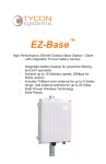
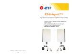
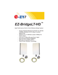
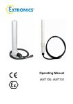
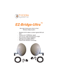
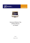
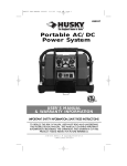
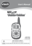
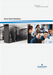
EZSB SolarBase ™ Solar Powered High Performance 250mW Outdoor Base Station / Client / Repeater ▫ ▫ ▫ ▫ ▫ Autonomous Off-Grid operation with <3 hours sun per day. >24Hr. Lithium Battery Backup Achieve up to 15 Mbit/sec speed; 25Mbps for 5GHz version Includes TriBand omni antenna for up to 0.3 miles range. Add external antenna for up to 20 miles. Field Proven Wireless Technology DANGER! Avoid Powerlines! You Can Be Killed! When following the instructions in this guide to install the device, take extreme care to avoid contact with overhead power lines, lights and power circuits. Contact with power lines, lights or power circuits may be fatal. We recommend to install device no closer than 20 feet to any power lines. Safety: For your own protection, follow these safety rules. ▫ ▫ ▫ ▫ ▫ Perform as many functions as possible on the ground Do not attempt to install the device on a rainy, windy or snowy day or if there is ice or snow accumulation at the install site or if the site is wet. Make sure there are no people, pets, etc. below when you are working on a roof or ladder. Watch out for any power lines which may be overhead, underground or behind walls, keeping safely clear of them with the antenna, ladders or any tools. See appendix for FCC RF exposure guidelines Recommended Tools: Phillips Screwdriver, 3mm Allen Wrench, 14mm Open End Wrench. Screws and screwdriver if mounting to a wall. NOTE: You should be familiar with using tools such as these before attempting installation of the device. You should be comfortable with working on a ladder. Getting Started It is recommended that you setup the SolarBase™system in your office or lab to get acquainted with the operation of the unit before installing outdoors. It’s always best to start with a fully charged battery. Controller won’t power the wireless card unless the battery voltage is >12V. You can recharge via POE into the POE IN port of the controller. Apply 24V and at least 2.5A POE to the POE IN port for at least 4 hours to fully charge the battery. Please help preserve the environment and return used batteries to an authorized depot 2 Qwik Install STEP 0: The SolarBase™ enclosure comes fully assembled. All that is needed is to connect the antenna to the N Type Female bulkhead connector and plug in the green power connector to the controller. When the green connector is plugged into the controller you should see LED’s light on the controller and the radio board inside the enclosure. We recommend that after office testing, that you disconnect the green connector to preserve the battery and only connect it again during installation in the field. STEP 1: Choose a mounting location with good line of sight to the remote locations. Also make sure the solar panel isn’t shaded even partially by any trees or poles. STEP 2: Mount the solar panel mount to the solar panel following the instructions included with the solar panel mount. Mount the solar panel to the pole or wall. It should be facing due south. To figure tilt, take your Latitude x 0.9 + 29. This will give you the correct winter tilt angle for your location. 3 STEP 3: Mount the SolarBase™ Install two bracket pieces to back of enclosure using 4 screws. The bracket can be mounted to a wall or to an existing pole up to 2” diameter. It’s best to mount the enclosure beneath the solar panel so the enclosure is shaded by the panel. Be sure to mount so that the enclosure cover can open without hitting the panel mount. TECH TIP: Microwaves travel in straight lines and they lose strength quickly when going thru buildings and trees. If there are objects in the microwave path, then useable distance will be reduced. 2.4GHz penetrates objects better than 5GHz. STEP 4: Connect the solar panel cable to the solar panel. Be sure to observe correct polarity. Red wire to + and Black wire to –. Tighten all wire feedthrus to secure the wires. Secure the loose cable using tie wraps so it doesn’t blow around in the wind. STEP 5: Install antenna that came with the unit or a larger gain external antenna. The small antenna that is supplied with the SolarBase™ is good for about 500 yds. To cover greater distances you will need to use a larger antenna. A 24db antenna should provide over 15 miles of coverage. The practical limit is about 12 miles because of the curvature of the earth unless the antennas are mounted at a higher elevation. STEP 6: Connect the green connector to the controller. A LED on the controller and LEDs on the radio board should light. STEP 7: Let the unit boot for about 2 mins then test the system by connecting to the unit thru the bottom POE IN port of the controller or thru the wireless interface. STEP 8: Make sure lid gasket is clean and free from any particles, then carefully close the cover, making sure that wires are clear of the seam and hinge area. STEP 9: Tighten the 4 seal screws evenly to seal the cover. Controller Notes: 1. When a battery is connected to the controller and the battery voltage is >12V the LOAd LED should be on. 2. When a 24V 2.5A POE power supply is plugged in and CAT5 cable connected to POE IN, the POE LED should be on. 3. If LOAd LED is off because battery voltage is <12V, it should come back on when battery is charged to >12V. 4. Controller is attached using Velcro fasteners so it is removable. 5. There is a secondary 12V output on the controller to power additional 12V devices. 6. Controller can support a solar panel up to 120W. 4 Software Settings 1. There is an HTML management system built into every SolarBase™ unit which is accessed thru a standard web browser. The unit can communicate thru a CAT5 Ethernet cable connection or thru the wireless connection, so you can manage remote units from a single location. NOTE: The device will usually go into a 2 minute reboot cycle When clicking on APPLY CHANGES. During this time it will be unresponsive. 2. IP ADDRESS: The first thing you want to do is reset the IP address to match the subnet of your network. Be careful not to create any IP address conflicts. Default IP address for the SolarBase™ is 192.168.1.1. To access the SolarBase™ with your browser your computer IP address must be on the same subnet ie; 192.168.1.xxx. The SolarBase™ ships with DHCP client enabled so if the unit has access to your network it will get its IP address automatically from your network. To find the units IP address use the Discovery Tool. TECH TIP: Download the EZ Discovery Tool from http://ezbridge.com/support/support.htm . This tool will assist you in finding the SolarBase™ on the network and allow you to change the IP address or set it as a DHCP client or disable DHCP Just select the unit, click on IP DETAILS, make selections and save changes directly to the device. 3. WIRELESS MODE: The SolarBase™ comes in Access Point (AP) mode by default. The SolarBase™ can be configured as an AP or Client or WDS or AP+WDS or Point to Point. It also can be configured as a repeater. AP—Communicates with multiple 802.11 clients in a point to multipoint configuration. Typically the AP can service about 35 clients. Client—Communicates with any 802.11 AP in a point to multipoint configuration. Security must be set to match the AP security before trying to connect. WDS—Communicates with up to 4 other WDS devices to create transparent bridging between several points. Communicates on MAC layer. To setup WDS you need the units to be on the same wireless channel; they must have the same WDS security settings; Enter unit A’s MAC address into Unit B’s WDS table and vice versa. AP+WDS—Used to create a bridge that also acts like an AP. The device communicates with another WDS device thru a WDS bridge and then broadcasts the signal as an AP to allow client devices to connect. Security for WDS and AP are set independently. AP+WDS would be used when there is a single internet source and multiple AP’s are needed to cover a wide area with WiFi coverage. For a successful WDS set5 up see WDS above. Point To Point—Creates a point to point transparent bridge between two points. This is normally used to connect two buildings or to create a backhaul between two points. To create a successful Point to Point setup, both units must be on the same wireless channel; set to same security settings; Enter Unit A’s MAC address into Unit B’s BSSID field and vice versa. Repeater—The unit picks up a signal from another wireless AP and rebroadcasts it to another location. This is useful if a signal needs to turn a corner around an impenetrable object or to increase the range of a source access point. If the unit is set as AP and Repeater is enabled then the Repeater will be in Client mode. If the unit is set as Client and Repeater is enabled then Repeater will be in AP mode. Security for the AP and Client are identical and must match the security setting of the source AP. DHCP should be disabled on the SolarBase™. Unit is AP and Repeater is Client: Setup the SolarBase™ as an AP and set it’s AP settings as desired. Enter the source AP’s SSID in the Repeater SSID field. If you want to lock the Repeater to that particular source AP then enter the source AP’s MAC address to the Repeater BSSID field otherwise leave it as all zeros. Unit is Client and Repeater is AP: Setup the SolarBase™ as a Client and perform a site survey and connect to the source AP. Enter the Repeater AP SSID in the Repeater SSID field. Leave the Repeater BSSID field as all zeros. 4. NETWORK OPERATION MODE: The default is for operation mode to be set to BRIDGE. A bridge passes all network traffic between the wireless and Ethernet ports of the device. This is the most common use. The SolarBase™ can also be set to ROUTER mode. In Router Mode there is a built in firewall and NAT that blocks traffic. If in AP mode and set to router then inbound Ethernet traffic is firewalled and to access the device you need to access thru the wireless side. If in Client Mode and set to router, the firewall is on the wireless side so inbound wireless traffic is routed thru the firewall. To access the device you need to be connected thru the Ethernet port. 5. SECURITY: Security is not configured by default. After you get the system working the way you want, we recommend assigning administrator user name and password and also setting wireless security by changing the encryption settings. WPA (AES) is the most advanced security type and is recommended for most applications. 6. SITE SURVEY: The site survey is a very useful tool to determine what wireless devices are within range of your SolarBase™ and could be a source of interference that could cause degraded performance. Go to WIRELESS and then click on SITE SURVEY then REFRESH. The 6 Technical Specifications Note: Subject to Change Without Notice 2.4GHz 5GHz 802.11b/g 802.11a 2400 to 2497MHz 5100 to 5875MHz 802.11b 100 to 250mW 802.11g 50 to 100mW 10 to 250mW -73 @ 54Mbps -84 @ 11Mbps -74dBm @ 54 Mbps -94dBm @ 6 Mbps Standards Radio Specifications Operating Frequency Available Transmit Power (software selectable) Receive Sensitivity Security Remote Configuration 64/128bit WEP, WPA, WPA2 By IP Address; thru Wireless or Ethernet, Telnet, SSH Antenna Specifications Antenna Gain Antenna Beamwidth (H/V) Polarization 3 dBi 5dBi 360/90 deg 360/90 deg Vertical Vertical Battery Specification Type LiFePO4 Lithium 12V 19Ah Backup Time >24 Hours Typical Battery Life 5 Years Solar Specification Panel Size Dimensions (L x W x H) 12V 60W , 25 year life 30” x 26.4” x 1.2” (767mm x 670mm x 30mm) Enclosure Mechanical Specifications Dimensions (L x W x H) 11” x 8.5” x 3.5” (279mm x 216mm x 89mm) Antenna Connector N Female Bulkhead—50ohm System Mechanical Specifications Mounting Pole (up to 2” dia) or Wall Weight 32 lb (14.5 kg) Environmental Specifications Operating Temperature -31 to 149Deg F (-35 to +65 Deg C) Humidity 0 to 100% RH 7 list will show all wireless devices including channel #, MAC Address and relative signal strength of all the devices within the range of the SolarBase™ . 7. FACTORY DEFAULTS: If at any time the system stops working because of changes made to the settings, you can get back to the original settings by resetting to factory defaults. Go to ADMIN | Reset Settings to Defaults. Any customized settings will be lost once this process is initiated. You can also reset to defaults through the Discovery Tool. Note: You need to supply the user name and password of the unit. If you cannot access the web page on the unit you can do a manual reset. Open the cover of unit. Power up the unit, wait 2 mins, press and hold the black reset button on the radio board for 15secs, release and wait 2 mins for reboot. 8. UPGRADE FIRMWARE: For the latest firmware point your browser to http://ez-bridge.com/support/support.htm Download the latest firmware to your PC. Select UPGRADE from the menu and then browse for the new file. Advanced Features The SolarBase™ has many advanced features if more functionality is desired. To access the advanced features, click on Advanced Web at the top of the menu tree. This will activate the advanced menu options. Since documentation for these advanced modes is too extensive to cover here please retrieve the documentation online at http://ezbridge.com/support/support.htm TECH CORNER Additional Information you may find useful 1. RAIN, SNOW, ICE – The frequencies being used by the SolarBase™ will not be affected by heavy rain or falling snow. You should not see any performance degradation due to inclement weather. 2. LIGHTNING – Lightning is the single worst enemy of outdoor electronics equipment. No electronics will survive a direct strike but there are close proximity strikes that can cause huge electrical fields to be generated which can damage electronic equipment. We have taken special care in the design of the SolarBase™ unit to ensure proper grounding of the electronics inside the enclosure to prevent damage from electrical storms. Always use DC grounded antennas. 8 3. INTERFERENCE – The most common cause of poor performance is due to interference from other wireless devices in the area. Interference can cause poor throughput and in the worse case, a lockup. It’s always good to do a site survey using the SolarBase™ control panel to see what other wireless devices are in the area and then choose a wireless channel that is at least 2 channels away from any strong offending signal. Keep in mind that even though all's well today somebody could setup a new system and create interference with your system at any time. If you suspect interference, change channels. There is also a Watchdog Timer built into the SolarBase™ which you can set to ping a remote device. If connection is lost the unit will automatically reboot. This is useful if you experience frequent lockups. Lowering the Beacon Interval on the Wireless Advanced Settings page can help improve performance in areas of intense interference. 4. RANGE — Useable distance with the included omnidirectional antenna is about 500yds at 5GHz and up to about 0.5 mile at 2.4GHz. To get more distance from the SolarBase™ you will need to use an external antenna which you can purchase from any of our distributors. A good 24dBi antenna should give about 15 miles distance. The practical limit is about 12 miles due to the curvature of the earth unless the equipment is mounted on a tall tower or mountain. The ACK timing default in the Wireless Advanced Settings page is 91. When the software sees the default value of 91 it actually switches to auto mode and ACK timing will be set automatically based on the best settings for the actual distance. If you over-ride the default value, the software will use the value that you entered. This is also true of other timing settings. We highly recommend leaving these settings at default for best performance. 5. ACCESS POINT CAPACITY — We recommend a max of about 35 clients per access point. The SolarBase™ can handle up to 50 but performance will be degraded with too many concurrent clients. 6. POWER CYCLING THE RADIO BOARD — Because this is a battery backup system, the only way to cycle power on the Radio Board is to open the enclosure and disconnect the green power connector from the controller. The Radio board can be rebooted through the web interface either through the wireless side or Ethernet side. You can also reboot the unit from the Discovery Tool. 7. COMMON MICROWAVE BARRIERS – Tinted windows are made by applying a metalized film to the window. If a window has tinting, it will usually block the microwaves and cause reduced performance of the SolarBase™. Concrete walls are also a significant barrier to microwave signals. Aluminum siding on houses is also a barrier to microwave signals. Wood frame houses covered with brick or stucco are pretty transparent to microwave signals and they will reduce the signal strength but 9 the signal will still pass thru the structure. We are bringing this up to you so you can better understand possible causes of performance issues. 8. VOICE OVER IP (VOIP) – The SolarBase™ supports all VOIP standards making it possible to use VOIP phones across any SolarBase™ link. We recommend setting the Data Rate to a fixed value when using VOIP if clicking is heard in the VOIP. You can set data rate to a fixed value on the Wireless Advanced Settings page. 9. TYPICAL APPLICATIONS: a. WiFi Hotspot—create a Wifi hotspot for patios, campuses, café’s, yards, hotels, etc. b. Repeater—Extend your network c. Community Wireless—Provide internet access to multiple houses or commercial buildings d. Marina Wireless—Provide internet access to a marina e. Campground Access—Provide internet access for a seasonal campground or recreation area f. Internet access sharing – share internet access with a friend or family member g. Link a Home Office to a Main Office - you can access shared files and folders as well as print to the main office printers and use other shared network devices remotely h. Link networks in multiple buildings together i. Add a high speed link between your home network and a PC in your remote studio or office which is located in an outbuilding on your property. j. Create a secure link for remote video and network based security cameras. k. Create a streaming video conference link between buildings. Because of the high bandwidth available with the SolarBase™, it easily supports streaming video technologies used for remote conferencing, like church meetings, business meetings, etc. Appendix: Federal Communication Commission Interference Statement This equipment has been tested and found to comply with the limits for a Class B digital device, pursuant to Part 15 of the FCC Rules. These limits are designed to provide reasonable protection against harmful interference in a residential installation. This equipment generates, uses and can radiate radio frequency energy and, if not installed and used in accordance with the instructions, may cause harmful interference to radio communications. However, there is no guarantee that interference will not occur in a particular installation. If this equipment does cause harmful interference to radio or television reception, which can be determined by turning the equipment off and on, the user is encouraged to try to correct the interference by one of the following measures: 10 Reorient or relocate the receiving antenna. Increase the separation between the equipment and receiver. Connect the equipment into an outlet on a circuit different from that to which the receiver is connected. Consult the dealer or an experienced radio/TV technician for help. FCC Caution: Any changes or modifications not expressly approved by the party responsible for compliance could void the user's authority to operate this equipment. This device complies with Part 15 of the FCC Rules. Operation is subject to the following two conditions: (1) This device may not cause harmful interference, and (2) this device must accept any interference received, including interference that may cause undesired operation. IMPORTANT NOTE: FCC Radiation Exposure Statement: This equipment complies with FCC radiation exposure limits set forth for an uncontrolled environment. This equipment should be installed and operated with minimum distance 20cm between the radiator & your body. The antenna(s) used for this transmitter must not be co-located or operating in conjunction with any other antenna or transmitter. Limited Warranty All Tycon Systems wireless products are supplied with a limited 12 month warranty which covers material and workmanship defects. This warranty does not cover the following: ▫ Parts requiring replacement due to improper installation, misuse, poor site conditions, faulty power, etc. ▫ Lightning damage. ▫ Physical damage to the external & internal parts. ▫ Products that have been opened, altered, or defaced. ▫ Water damage for units that were not sealed or mounted according to user manual. ▫ Units that were not properly grounded. ▫ Usage other than in accordance with instructions and the normal intended use. Do not return any products until you receive a Return Material Authorization (RMA) number. Products received without a valid RMA number will be rejected and returned to sender. Warranty Repairs All returns must have a valid RMA number written clearly on the outside of the box. Without an RMA number the shipment will be refused. For 11 customers located in United States and Canada, customer pays all shipping charges incurred to ship the product to Tycon Systems. Tycon Systems pays shipping charges to return the product to the original purchaser. For all other countries, the original purchaser shall pay all shipping, broker fees, duties and taxes incurred in shipping products to and from Tycon Systems. Provided the goods have not been modified or repair attempted by someone other than Tycon Systems, at the option of Tycon Systems, products may be returned either as repaired or replaced. If it is determined that there is no fault found (NFF) on a unit within warranty, the customer will be charged $75 USD for testing time. For products out of warranty, the standard NFF charge is $200. This charge will be at the discretion of Tycon Systems. The RMA number is valid for 14 days from date of issue. The product must be received by the repair depot within these 14-days or the shipment may be refused. Shipping and Damage Claims All shipping damage claims are the purchaser's responsibility. Inspect each shipment upon delivery and IMMEDIATELY report all damage, to the carrier. There may be time limits and inspections may be required. Phone: 801-432-0003 [email protected] 8000031 Rev 1 EZSB SolarBase™ Qwik Install Guide 12