1
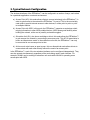
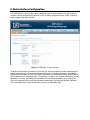
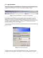
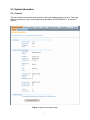
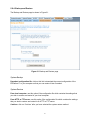
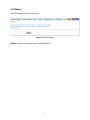
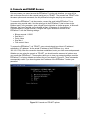
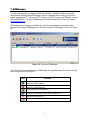
Teletronics EZPlatform™ AP/Hotspot/Repeater User Manual v1.2 © 2008 Teletronics International, Inc Table of Contents 1. Product Overview ...................................................................................................3 2. Specifications .........................................................................................................4 3. Typical Network Configuration ............................................................................... 5 4. Hardware Setup and Status LEDs ......................................................................... 6 5. Web Interface Configuration .................................................................................. 7 5.1. Login Information .................................................................................... 8 5.2. System Information ................................................................................. 9 5.2.1. General .....................................................................................9 5.2.2. Wireless Status ........................................................................ 11 5.3. Network Settings ..................................................................................... 12 5.3.1. WAN ......................................................................................... 12 5.3.2. LAN .......................................................................................... 15 5.4. WLAN1 and WLAN2 ............................................................................... 17 5.4.1. Basic .........................................................................................17 5.4.2. Security .................................................................................... 19 5.4.3. AP Settings ...............................................................................21 5.4.4. SU Settings (WLAN1 only) ....................................................... 23 5.4.5. Advanced ................................................................................. 24 5.4.6. MAC Filtering ............................................................................25 5.5. Bandwidth Control ...................................................................................27 5.6. Administration ......................................................................................... 29 5.6.1. System Configuration ............................................................... 29 5.6.2. Admin IP Filter ..........................................................................31 5.6.3. Password ..................................................................................32 5.6.4. Backup and Restore .................................................................33 5.6.5. Firmware Upgrade ....................................................................35 5.7. Log .......................................................................................................... 36 5.8. Reboot .....................................................................................................37 6. Console and TELNET Access ............................................................................... 38 7. EZManager ............................................................................................................ 39 8. Frequently Asked Questions ..................................................................................40 2 1. Product Overview Teletronics' EZPlatform™ AP/Hotspot/Repeater is designed for high-power access point, hotspot and repeater applications. A powerful end-to-end system for a wireless Internet network can be built by integrating the EZPlatform™ with Teletronics TT™ subscriber units and other radios. The simplicity of use of the EZPlatform™ allows operators to quickly bring service to their customers, and with its two serial ports and two Ethernet ports the unit can easily incorporate GPS, GPRS, RFID, VoIP, surveillance cameras, field meters, motion sensors and data networks for multiple industrial and commercial applications. The EZPlatform™ is available in single or dual radio configuration, with 1 W (2.4 GHz) and 600 mW (2.4/5.8 GHz) radio card options. 3 2. Specifications Technical Information Standard compliance Bandwidth Control Networking Security Management Wireless Enclosure Status monitoring Operating temperature IEEE 802.3 10/100BASE-T with autonegotiation Mac address-based, specific and default upload/download rates WAN: static IP address/DHCP client LAN: DHCP server SNMP, remote syslog, VPN pass-through (IPsec/PPTP), DDNS Administrator IP address filtering Web-based management HTTP, HTTPS, TELNET Web-based update, backup and restore 802.11a/b/g, 900 MHz/2.4 GHz/5.8 GHz AP/SU mode, adjustable TX power WEP, WPA, and WPA2 encryption Turbo mode, WDS, MAC address filtering NEMA 4, ruggedized and weather proof Network status, system log (compact and detailed mode) -20° C to + 70° C Hardware Specifications CPU Memory Boot loader Ethernet Serial port Mini PCI LEDs Power options Dimensions Power consumption Operating system Intel® IXP422 226 MHz network processor 64 MB SDRAM, 16 MB flash RedBoot Two 10/100BASE-T ports Two RS-232 ports Two Mini PCI Type III slots Power, WLAN1 status, WLAN2 status Power over Ethernet, 10-48 VDC 8 in x 7.5 in x 2.5 in 25 W maximum Linux, 2.6.x kernel 4 3. Typical Network Configuration The wireless interfaces of the EZPlatform™ can be configured in a number of ways, each suited for a particular application or network environment: a) Access Point (AP): this mode allows clients to connect wirelessly to the EZPlatform™ in order to gain access to the network the EZPlatform™ is part of. This is the most widely used mode to provide Internet access to other devices, in either point-to-point or pointto-multipoint fashion. b) Access Point with WDS: in this mode, the EZPlatform™ operates as a wireless switch, relaying information to other WDS-enabled devices. WDS allows great flexibility when building the network, at the cost of possibly reduced throughput. c) Subscriber Unit (SU): also known as bridge or client, this mode allows the EZPlatform™ to gain access to a network by connecting to an access point. This AP-SU association is known as infrastructure mode. In the subscriber unit mode, the EZPlatform™ can only be connected to one access point at a time. d) Ad hoc mode: also known as peer-to-peer, this non-hierarchical mode allows clients to communicate with each other directly without the need of an access point. In the EZPlatform™, each of the two wireless interfaces can be configured independently. They can also operate simultaneously regardless of the mode being used in each interface. For example, WLAN1 can be working in subscriber unit mode while WLAN2 is operating as an access point with WDS. 5 4. Hardware Setup and Status LEDs Hardware Setup Figure 1 shows how to connect the EZPlatform™. Figure 1. Network and power connections The purpose of this setup is to connect the EZPlatform™ so that it can be configured with a computer via the web interface of the EZPlatform™. The power over Ethernet (PoE) module allows you to send/receive data and power the EZPlatform™ with a single cable. When connecting the antennas, care must be taken so that the antennas are properly mounted to avoid mutual interference, especially if both wireless interfaces will be operated in the same 802.11 mode. WLAN1 and WLAN2 are the fixed designations for the two wireless interfaces. WLAN1 is wired to the antenna port that is closer to the hinges of the NEMA 4 enclosure; WLAN2 is wired to the antenna port farther from the hinges of the enclosure. Status LEDs The behavior of the LEDs mounted on the enclosure is explained in the following table. LED Position Status Off WLAN1 Left Blinking Solid on Power Center WLAN2 Right Off Solid on Off Blinking Solid on Interpretation Radio card not detected / wireless off No station(s) associated (in AP mode) Not associated to an AP (in SU mode) Station(s) associated (in AP mode) Associated to an AP (in SU mode) Power off Power on Radio card not detected / wireless off No station(s) associated Station(s) associated 6 5. Web Interface Configuration The EZPlatform™ can be conveniently configured using its web interface. The web interface provides intuitive navigation and options for you to easily configure the unit. Figure 2 shows a sample page of the web interface. Figure 2. EZPlatform™ web interface Throughout this manual, the buttons on the top row, which are light blue when unselected and orange when selected, will be denominated ‘primary tabs’. Likewise, the buttons immediately below the primary tabs, which are of a darker blue when unselected and orange when selected, will be referred to as ‘secondary tabs’. For instance, in Figure 2 the ‘System Information’ primary tab and the ‘General’ secondary tab are selected. To access a secondary tab, you must first click on the primary tab to which the secondary tab belongs. Each primary tab has a different set of secondary tabs. Some primary tabs do not have secondary tabs. 7 5.1. Login Information After properly connecting and powering the unit, wait for the unit to finish the boot-up process. On the computer connected to the EZPlatform™ via Ethernet, open a browser and point it to the IP address of the EZPlatform™ (192.168.1.124 by default), as shown in Figure 3. Figure 3. Entering the EZPlatform™ IP address in the address bar The IP address of the EZPlatform™ can be changed once you have logged in. In order to access the web interface, the computer needs to be configured for the subnet to which the EZPlatform™ belongs. By default, both HTTP and HTTPS are enabled, so you can log in using the ‘http://’ or ‘https://’ headers, respectively. HTTP and HTTPS access can be enabled or disabled independently after you have logged in. To log in to the web interface, enter the user name and password in the prompt that appears, as shown in Figure 4. Figure 4. User name and password The default user name is ‘admin’ and the default password is ‘admin’. The password can be changed once you have logged in. After logging in, you will see the page shown in Figure 5. 8 5.2. System Information 5.2.1. General The web interface is the home page and thus is the page displayed when you log in. This page displays a summary of the current configuration and status of the EZPlatform™, as shown in Figure 5. Figure 5. System Information page 9 To view details of the Linux operating system, the Linux kernel and network settings, click on the ‘View System Details’ button. The page in Figure 6 will be displayed: Figure 6. System Log Details This page shows a series of commands executed on the Linux kernel, and their corresponding output immediately below each command. 10 5.2.2. Wireless Status The Wireless Status page is shown in Figure 7. Figure 7. Wireless Status page The Wireless Status page displays current status and associations of the wireless interfaces (WLAN1 and WLAN2). Under this page you can see the configuration information for each WLAN interface, such as MAC address, operation mode, SSID, etc. A list of available access points and relevant information is shown if the WLAN interface is operating in SU mode. A list of associated stations and relevant information is shown if the WLAN interface is operating in AP mode. You may need to refresh the page so that the latest changes in the wireless environment are reflected on the page. 11 5.3. Network Settings 5.3.1. WAN The WAN page is shown in Figure 8. Figure 8. WAN page WAN Assignment WAN Interface: this setting allows you to designate which one of the four interfaces acts as the Wide Area Network (WAN) side of the EZPlatform™. The purpose of the WAN is to communicate with the “outside” of the network to retrieve the data requested by the LAN side (the “inside” of the network). Figure 9 shows which physical port on the PCB corresponds to which network interface. ETH1: Ethernet port farther from the serial ports on the PCB. 12 ETH2: Ethernet port closer to the serial ports on the PCB. WLAN1: Mini PCI slot closer to the Ethernet ports in the PCB, wired to the antenna port closer to the hinges of the enclosure. WLAN2: Mini PCI slot farther from the Ethernet ports in the PCB, wired to the antenna port farther from the hinges of the enclosure. Figure 9. Network interfaces of the EZPlatform™ WAN IP Settings IP address mode: how to assign an IP address to the WAN side of the EZPlatform™ Static: manually assign an IP address. DHCP: make the EZPlatform™ act as a DHCP client so that a DHCP server can automatically configure its IP settings. IP address: the unique network address of the EZPlatform™ in the WAN. Subnet mask: the mask that logically organized the IP address into its corresponding subnetwork. Default gateway: the device which will act as the agent for IP addresses that are outside the WAN subnet. Preferred DNS server: the server that will perform translation between URLs and IP addresses Alternate DNS server: the server that will resolve DNS requests if the preferred DNS server is not available. DDNS certificate: the DDNS feature of the EZPlatform™ is designed to work with the DDNS implementation of freedns.afraid.org. The certificate issued by freedns.afraid.org will allow the EZPlatform™ to periodically send IP address updates to freedns.afraid.org so that your URL is always mapped in DNS to the EZPlatform™, even if the IP address of the EZPlatform™ changes. To obtain a DDNS certificate, go to http://freedns.afraid.org, create an account and 13 follow the instructions in the 'Dynamic DNS' section. Once you have set up the DDNS relation, obtain the DDNS certificate from the 'Wget Script' link. Update time (s): how often to send IP address updates to freedns.afraid.org. Save: store the changes made on this page. Cancel: undo the changes made on this page. 14 5.3.2. LAN The LAN page is shown in Figure 10. Figure 10. LAN page DHCP Server Enable DHCP server: whether the EZPlatform™ should act as DHCP server and thus automatically configure the IP settings of DHCP clients. Yes No Starting IP address: the first IP address that will be used in the configuration of DHCP clients. Ending IP address: the last IP address that will be used in the configuration of DHCP clients. Subnet mask: the subnet mask that will be used in the configuration of DHCP clients. Default gateway: the default gateway that will be used in the configuration of DHCP clients. Preferred DNS server: the preferred DNS server that will be used in the configuration of DHCP clients. 15 Alternate DNS server: the alternate DNS server that will be used in the configuration of DHCP clients. Lease time (min): the period of time the IP address of a DHCP client will be reserved exclusively for said client. Save: store the changes made on this page. Cancel: undo the changes made on this page. 16 5.4. WLAN1 and WLAN2 WLAN1 and WLAN2 are the fixed designations for the two EZPlatform™ wireless interfaces. WLAN1 is the radio card closer to the Ethernet ports and WLAN2 is the radio card farther from the Ethernet ports, as explain in section 5.3.1. The configuration pages of WLAN1 and WLAN2 are identical, with the exception that WLAN2 cannot be used in SU mode. 5.4.1. Basic The LAN page is shown in Figure 11. Figure 11. Basic page Operation Mode Wireless on/off: whether to use the WLAN interface or not. On: enable the WLAN interface. Off: disable the WLAN interface. Operation mode: the role of the WLAN interface in the network. AP: access point. SU: subscriber unit, also know as bridge or client. 17 Basic Settings SSID: the service set identifier of the WLAN interface. An AP and an SU must have the same SSID to associate each other. Never assign the same SSID to WLAN1 and WLAN2. RF TX power (dBm): the radio frequency transmission power at which the radio card will operate. The value entered must be within the specifications of the radio card being used. 802.11 mode: which amendment of the IEEE 802.11 standard to use. The selected mode must be supported by the radio card being used. 802.11a: 5.8 GHz, OFDM, 54 Mbps. 802.11b only : 2.4 GHz, DSSS, 11 Mbps. 802.11g only: 2.4 GHz, OFDM, 54 Mbps. 802.11b/g: mixed use of 802.11b and 802.11g. Channel: the radio frequency channel to be used. Channels 36-165: for use with 802.11a mode. Channels are non-overlapping. Channels 1-11: for use with 802.11b and 802.11g modes. May also be used to drive certain 900 MHz radio cards. If the difference between any two channels is equal to or greater than 5, then the channels do not overlap, otherwise the channels overlap and interference may occur. For example, channels 1, 6 and 11 do not overlap and can be used simultaneously without causing mutual interference. S-Turbo Channels: for use with turbo mode only. Transmission rate: the data rate the WLAN interface should use. ‘Best (automatic)’ is recommended in most cases. Turbo mode: this feature, also known as Atheros Super AG, doubles the nominal data transfer rate by using two channels simultaneously. Both sides of the wireless link must be configured for turbo mode and have Atheros Super AG compatible radio cards. Save: store the changes made on this page. Cancel: undo the changes made on this page. 18 5.4.2. Security The Security page is shown in Figure 12. Figure 12. Security page Encryption Type Encryption type: select the encryption type you wish to use. None: no encryption. WEP: Wired Equivalent Privacy, a deprecated algorithm proven to have serious weaknesses. WPA: Wi-Fi Protected Access, IEEE 802.11i. WEP Settings 19 Authentication: select the WEP authentication type. Open: stations are always automatically authenticated and associated, but cannot pass traffic if they do not have a matching WEP key. Shared: stations need to have the same WEP key as the AP to be authenticated. Shared authentication is considered a security risk since the encryption scheme is sent over the air during the authentication negotiation process, making it easier for a hacker to discover the WEP key. Default WEP key: data received is decrypted using any of the four WEP keys, but data transmitted is encrypted using the default WEP key only. WEP key length: whether to use a 64-bit or a 128-bit key. A longer key is considered to be more robust. WEP key 1-4: enter the WEP key to be used. The key must be of the same length as specified in ‘WEP key length’ and may only contain hexadecimal digits (0-9, A-F). WPA Settings WPA mode: select which WPA mode should be used WPA: released before the completion of the IEEE 802.11i standard and specifically designed to work with pre-WPA wireless network cards. WPA2: implements the full 802.11i standard but may not work with some older network cards. WPA and WPA2 Cipher: the specific algorithm for performing encryption and decryption TKIP: Temporal Key Integrity Protocol AES: Advanced Encryption Standard TKIP and AES Pre-shared key: the password to be used for WPA. It must be between 8 and 63 characters long. Save: store the changes made on this page. Cancel: undo the changes made on this page. 20 5.4.3. AP Settings The configuration in AP Settings will only be applied when the WLAN interface is being used in AP mode. If SU mode is used, the configuration in AP Settings will not be used, but it will be retained nonetheless. The AP Settings page is shown in Figure 13. Figure 13. AP Settings page Basic Settings Broadcast SSID: whether to broadcast the AP’s SSID over the air for all clients to know of its presence. If the SSID is not broadcast, the only clients that will be able to connect to the AP are those which know the AP’s SSID beforehand and specifically request to be connected with said SSID. Not broadcasting the SSID should not be relied on as a security measure. Yes No WDS WDS: with WDS, the WLAN interface operates as a wireless switch, relaying information to other WDS-enabled devices. WDS allows great flexibility when building the network, at the cost of possibly reduced throughput. WDS and WPA are incompatible, so these two features should 21 not be used at the same time. When using WDS, all WDS stations must use the same channel and different SSIDs. Enable Disable AP MAC address 1-6: specify the MAC addresses of the WDS-enabled access points to which you wish to relay data. MAC addresses must be entered as octets separated by colons (e.g.: 00:60:B3:F8:C6:D4). Both lower and upper case letters are acceptable. Save: store the changes made on this page. Cancel: undo the changes made on this page. 22 5.4.4. SU Settings (WLAN1 only) Only WLAN1 has the ‘SU Settings’ secondary tab, since WLAN2 can only be operated in AP mode. The configuration in SU Settings will only be applied when the WLAN interface is being used in SU mode. If AP mode is used, the configuration in SU Settings will not be used, but it will be retained nonetheless. The SU Settings page is shown in Figure 14. Figure 14. SU Settings page Basic Settings Wireless mode: choose the wireless mode to be used with the SU mode Infrastructure: for AP-SU hierarchical links Ad hoc: peer-to-peer mode. This is a non-hierarchical direct communication mode between SUs, where an AP is not required. BSSID: if a client sees two APs with the same SSID, there will be some ambiguity as to which AP the client should select to establish a connection. Specifying the BSSID (the MAC address of the desired AP) resolves such ambiguity. Both SSID and BSSID must match for a wireless link to be established. The BSSID must be entered as octets separated by colons (e.g.: 00:60:B3:F8:C6:D4). Both lower and upper case letters are acceptable. Save: store the changes made on this page. Cancel: undo the changes made on this page. 23 5.4.5. Advanced The Advanced page is shown in Figure 15. Figure 15. Advanced page Advanced Fragmentation threshold (bytes): the maximum allowed size of packets to be transmitted. If a packet exceeds this threshold, it will be fragmented into smaller packets. RTS threshold (bytes): packets whose size exceeds this threshold will be transmitted using the RTS/CTS protocol. Beacon period (ms): the interval at which a unit in ad hoc mode sends beacons to nearby wireless devices to indicate its presence. Save: store the changes made on this page. Cancel: undo the changes made on this page. 24 5.4.6. MAC Filtering The MAC Address Filtering page is shown in Figure 16. Figure 16. MAC Address Filtering page MAC Address Filtering MAC Address Filtering: this function allows you to precisely control which devices are allowed to pass traffic through the WLAN interface. This feature can only be used when the WLAN interface is working in AP mode. Enable: when enabled, only the devices whose MAC address is listed in the table are allowed to pass traffic through the WLAN interface Disable: any device can pass traffic through the WLAN interface MAC Address: enter the MAC address of the device you wish to authorize to have access to the WLAN interface. The MAC address must be entered as octets separated by colons (e.g.: 00:60:B3:F8:C6:D4). Both lower and upper case letters are acceptable. Nickname: here you can enter a note to remind yourself what device or location corresponds to the MAC address entered. This field is provided for your convenience and has no impact on the operation of the EZPlatform™. 25 Save: store the changes made on this page. Cancel: undo the changes made on this page. 26 5.5. Bandwidth Control Bandwidth control allows you to limit the rate at which devices can upload to or download from the EZPlatform™. The Bandwidth Control page is shown in Figure 17. Figure 17. Bandwidth Control page This feature allows you to set specific upload and download rates for the devices you specify. If you want to completely prevent a device from passing any traffic through the EZPlatform™, you can assign its data rates to zero. On the other hand, if you want to assign no restrictions whatsoever to a particular device, assign it a very high data rate such as 60000 kbps Basic Settings Bandwidth control: choose whether you want to enable bandwidth control. Enable: when you enable bandwidth control, you must specify a default upload rate and a default download rate for those devices that do not have an explicit rule set up for them, 27 i.e. for devices whose MAC address does not appear in the table at the bottom of the page. Typically, you will want the default rates to be lower (significantly in some cases) than the rates of the explicitly defined rules. This way, if a device has an explicitly defined rule, you should think of it as privileged rather than restricted. Disable: no bandwidth limit rules apply for any device connected to the EZPlatform™. Default upload rate (kbps): the maximum rate at which devices that do not have an explicit rule set up for them can upload data to the EZPlatform™. Default download rate (kbps): the maximum rate at which devices that do not have an explicit rule set up for them can download data from the EZPlatform™. Bandwidth Control Rules MAC address: enter the MAC address of the device for which you wish to set up a bandwidth rule. The MAC address must be entered as octets separated by colons (e.g.: 00:60:B3:F8:C6:D4). Both lower and upper case letters are acceptable. Upload rate (kbps): the maximum rate at which the device is allowed to upload data to the EZPlatform™. Download rate (kbps): the maximum rate at which the device is allowed to download data from the EZPlatform™. Add new rule: after you have completed the fields ‘MAC address’, ‘Upload rate (kbps)’ and ‘Download rate (kbps)’, click on the ‘Add new rule’ button to save the rule. The new rule will appear in the table at the bottom of the page. Remove existing rule: if you wish to remove a rule you have previously set up, select it from the ‘Bandwidth control’ rules drop-down menu and click on the ‘Remove existing rule’ button to delete the rule. You cannot edit a rule: you will have to delete the rule you wish to modify and create a new one in its place. Apply: when you have finished defining your bandwidth rules, click on the ‘Apply’ button for them to take effect. Unlike most pages in the web interface, the settings for bandwidth control take effect immediately and there is no need to reboot. 28 5.6. Administration 5.6.1. System Configuration The System Configuration page is shown in Figure 18. Figure 18. System Configuration page Bandwidth Control Rules Host name: assign a name to the EZPlatform™ so that you can identify it in the network. This field has no impact on the operation of the EZPlatform™. Services HTTP: enable or disable access to the web interface via Hypertext Transfer Protocol. Enable Disable HTTPS: enable or disable access to the web interface via Hypertext Transfer Protocol over Secure Socket Layer. 29 Enable Disable TELNET: enable or disable access to the web interface via Telecommunication Network. Enable Disable SNMP: enable or disable monitoring of the EZPlatform™ via Simple Network Management Protocol. Enable Disable Read community string: the password that allows you to perform queries to the EZPlatform™ (snmpwalk, snmpget, etc) to retrieve monitoring information. Write community string: the password that allows you to write to MIBs (Management Information Base) via commands such as snmpset. sysContact: the OID which refers to contact information of the person responsible for the EZPlatform™. sysLocation: physical location of the EZPlatform™. syslog: enable or disable forwarding of system events to a server. Enable Disable syslog server IP address: the IP address of the server that will receive event messages from the EZPlatform™. Save: store the changes made on this page. Cancel: undo the changes made on this page. 30 5.6.2. Admin IP Filter The Admin IP Filter page is shown in Figure 19. Figure 19. Admin IP filter page Administrator IP address filtering is a security feature that allows you to restrict who is authorized to access the web interface and change the configuration of the EZPlatform™. When one or more filters have been set up, only the specified IP addresses will be allowed to access the web interface. Admin IP Filter IP address: the IP address of the device you wish to grant access to the web. Subnet mask: the subnet mask to be applied to the IP address. A subnet mask of 255.255.255.255 should be used for single hosts. Add new filter: after you have completed the ‘IP address’ and ‘Subnet mask’ fields, click on the ‘Add new filter’ button to add assign administrator privileges to the designated IP address. The new filter appears in the table at the bottom of the page. Remove existing filter: to remove previously assigned administrator privileges from an IP address, choose the corresponding device in the drop-down menu and click on the ‘Remove existing filter’ button. Save: when you have finished defining authorized hosts, click on the ‘Save’ button for the changes to take effect. 31 5.6.3. Password The Password page is shown in Figure 20. Figure 20. Admin IP filter page Password Current password: enter your current password to confirm your identity. New password: enter the new password that you wish to use. The password must not exceed 8 characters in length. Confirm new password: enter once again the new password that you wish to use Apply: when you have finished completing the fields on this page, click on the ‘Apply’ button for the changes to take effect. Unlike most pages in the web interface, the settings take effect immediately and there is no need to reboot. 32 5.6.4. Backup and Restore The Backup and Restore page is shown in Figure 21. Figure 21. Backup and Restore page System Backup Download configuration file: click on this link to download the current configuration of the EZPlatform™ to your computer so that you can restore it later if needed. System Restore From local computer: use this option if the configuration file which contains the settings that you wish to restore are located in your local computer. From HTTP or FTP server: use this option if the configuration file which contains the settings that you wish to restore are located in an HTTP or FTP server. Continue: click on ‘Continue’ after you have selected the system restore method. 33 System Restore Reset all settings to default: click on this button to restore all the settings of the EZPlatform™ to factory default, including the IP address. 34 5.6.5. Firmware Upgrade The Firmware Upgrade page is shown in Figure 22. Figure 22. Firmware Upgrade page Firmware Upgrade Browse: click on this button to browse your local computer and choose the firmware binary file you wish to load to the EZPlatform™. Upgrade firmware: after selecting the binary file location, click on the ‘Upgrade firmware’ button. 35 5.7. Log The Log page is shown in Figure 23. Figure 23. Log page This page shows you important events that have been logged by the EZPlatform™ . Events are displayed chronologically, with the most recent ones displayed at the bottom of the list. 36 5.8. Reboot The Reboot page is shown in Figure 24. Figure 24. Reboot page Reboot: clicking on this button reboots the EZPlatform™. 37 6. Console and TELNET Access If for any reason you cannot access the EZPlatform™ via the web interface, you may still be able to recover the unit via the console (serial port) or TELNET. The console and TELNET offer the same options and commands, the only difference being the way they are accessed. To access the EZPlatform™ via the console, connect the serial cable EZPlatform™ to a computer using a serial cable. Use the serial port in the EZPlatform™ that is closer to the Ethernet ports. In the computer, open a HyperTerminal window or similar program. In Microsoft Windows, the HyperTerminal can be located at Start Æ Programs Æ Accessories Æ Communications Æ HyperTerminal. Configure the HyperTerminal to connect to the EZPlatform™ with the following settings: Bits per second: 115200 Data bits: 8 Parity: None Stop bits: 1 Flow control: None To access the EZPlatform™ via TELNET, open a terminal and type ‘telnet <IP address>’, substituting ‘<IP address>’ for the actual IP address of the EZPlatform (e.g.: telnet 192.168.1.124). After the connection has been established, enter your user name and password. Whether you are using the console or TELNET, you should see the same set of options once you access the EZPlatform™. These options allow you to view your network settings, reset the EZPlatform™ to factory defaults and reboot the unit, as shown in Figure 25. These commands are especially useful if you have forgotten the IP address of the EZPlatform™ and/or your password. Figure 25. Console and TELNET options 38 7. EZManager To help you administer your network easily and effectively, Teletronics offers free network administration software called EZManager, which is compatible with virtually all Teletronics radios, including the TT™ series, the TTX™ series, the SLAB™ series, the EZBridge™ series and the EZPlatform™. A copy of EZManager can be downloaded from Teletronics’ website, www.teletronics.com. EZManager does not require installation: you can just uncompress the download file and execute the file called ‘EZManager.exe’. The main interface of EZManager is shown in Figure 26. Figure 26. Teletronics EZManager The functions of some of the buttons in EZManager are explained below, as well as how they can be used with the EZPlatform™. Icon Function Scans the network for Teletronics devices and shows their IP address and MAC address. Allows you to change the IP address, subnet mask and default gateway of the EZPlatform™ Loads firmware to the EZPlatform™ Opens the web interface of the EZPlatform™. The computer needs to be in the same subnet as the EZPlatform™ Reboots the EZPlatform™ Resets all settings of the EZPlatform™ to factory default 39 8. Frequently Asked Questions 1. What is the default IP address, user name and password of the EZPlatform™? IP address: 192.168.1.124 User name: admin Password: admin 2. How do I know if the EZPlatform™ has finished booting up? There are a number of ways to tell that the EZPlatform™ has concluded the boot up process: The WLAN1 and the WLAN2 LEDs on the enclosure are solid at the beginning of the boot up sequence. When the boot up sequence is complete, both LEDs begin to blink. You can ping the unit continuously as it is booting up. When the EZPlatform™ has finished booting up, it will respond to a ping request. If you access the EZPlatform™ via the console (serial port) while it is booting up, you will be able to see all the details of the boot up sequence. When you notice that the text ‘Please press Enter to activate this console.’ appears and the screen remains still, the EZPlatform™ has finished booting up. 3. Which antenna port is WLAN1? Which one is WLAN2? WLAN1 is the antenna port that is closer to the hinges of the enclosure; on the PCB, it is the radio card that is closer to the Ethernet ports. WLAN2 is the antenna port that is farthest from the hinges of the enclosure; on the PCB, it is the radio card that is farthest from the Ethernet ports. 4. Which serial port should I use to access the console? Use the serial port that is closer to the Ethernet ports. 5. I forgot the IP address of the EZPlatform™. You can recover the IP address of the EZPlatform™ in two ways: EZManager: connect the EZPlatform™ to a computer running EZManager and scan the network. EZManager will detect the EZPlatform™ and display its IP address. Console: choose the option ‘Network Information’ to display the IP settings of the EZPlatform™ 6. I forgot the password of the EZPlatform™, or cannot access the web interface. To access the EZPlatform™ again, you will need to reset all settings to factory default. You can do this in two ways: EZManager: connect the EZPlatform™ to a computer running EZManager and scan the network. EZManager will detect the EZPlatform™. Click on the ‘Set settings to factory default’ icon. Console: choose the option ‘Factory Defaults’ and confirm your selection, then choose ‘Reboot’. 7. Does the push button on the PCB reset or reboot the EZPlatform™? No, the push button near the serial ports is for factory testing only and does not affect the operation of the EZPlatform™. 8. I am having trouble establishing a wireless link. 40 If the access point or the subscriber unit does not appear in the Wireless Status page, follow these steps: Test the radios at a close distance (e.g.: on the same tabletop) without amplifiers. Verify that you are using the correct network configuration at both ends of the link (AP, AP with WDS, SU or ad hoc). Make sure the WLAN interface you are using and the other end of the link are using the same SSID. Check that the antennas are precisely aligned. Verify all connections and that all cables and connectors are tightly coupled. Reset the radios at both ends to factory default and configure both radios again. 9. I was able to establish a wireless link, but I cannot pass any traffic. If you see correct wireless association in the Wireless Status page, but are unable to ping the remote site or pass any other traffic, follow these steps: Make sure the WLAN interface you are using and the other end of the link are on the same subnet. Disable encryption at both ends. Reboot both radios. 10. I can pass traffic but the throughput is very low or I am losing packets. Follow these steps: Revise your RF calculations to make sure the equipment you are using can produce a reliable connection for the current link distance. Check that the antennas are precisely aligned. Check that you are not causing self-interference or receiving interference from your RF environment. Verify that the radios at both ends have enough vertical clearance to keep the Fresnel zone unobstructed. 11. I have other questions or comments about the EZPlatform™. How can I contact technical support? You can contact us by: Online Helpdesk: http://teletronics.com/Supportform.html#signup Email: [email protected] Telephone: 1-301-309-8500 Fax: 1-301-309-8851 Postal mail: Teletronics International 2 Choke Cherry Rd Rockville, MD 20850 USA 41