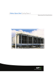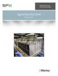
1
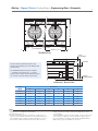
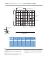
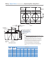
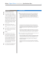
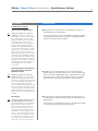
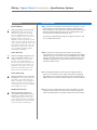
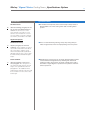
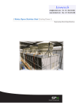
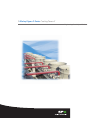
/ Marley Sigma F Series Cooling Tower /
Engineering Data & Specifications
Marley / Sigma F Series Cooling Tower / Table of Contents
Engineering Data
Schematic4
Support5
Piping7
10
Temperature Control
Environmental11
Specifications / Base
Base12
Thermal Performance
13
Construction14
Fan Deck and Fan Cylinder
15
Mechanical Equipment
15
16
Fill, Louvers and Drift Eliminators
Hot Water Distribution System
17
Casing17
Access and Safety
18
18
Cold Water Basin
Scope of Work
19
Specifications / Options
Cold Water Basin Options
Stainless Steel Cold Water Basin
Watertight Partition between Tower Cells
Basin Heater
20
20
20
Convenience and Safety Options
Fiberglass Stairway
Wood Stairway
Plenum Walkway
Ladder Extension
Ladder Safety Cage
Hot Water Basin Covers
Air Inlet Screens
21
21
22
22
22
22
23
Appearance Options
Architectural Casing
Cased Guardrail
23
23
Control Options
Control System
Variable Speed Drive
Vibration Limit Switch
24
25
26
Miscellaneous Options
Galvanized Steel Ladder
Fiberglass Ladder
Low Noise Tower
Fire-Retardant Fiberglass
Fan Cylinder Extension
Increased Wind and/or Earthquake Load
Premium Hardware
26
26
27
27
27
27
27
Marley / Sigma F Series Cooling Tower /
The Sigma F Series
is a field-erected, crossflow,
fiberglass-structure cooling tower designed
to serve normal air conditioning and refrigeration
systems as well as medium sized industrial loads.
Evolving from the crossflow concept of cooling tower
pioneered by Marley in 1938, and incorporating over
65 years of design advancements, the Sigma F Series
represents the current state of the art in this cooling
tower category.
This booklet not only relates the language to use
in describing an appropriate Sigma F Series cooling
tower—but also defines why certain items and
features are important enough to specify with the
intention of insisting upon compliance by all bidders.
The left hand column of pages 12 through 27
provides appropriate text for the various specification
paragraphs, whereas the right hand column comments
on the meaning of the subject matter and explains its
value.
Pages 12 through 19 indicate those paragraphs which
will result in the purchase of a cooling tower which
will not only accomplish the specified thermal
performance, but which will include normal operation
and maintenance-enhancing accessories and features.
It will also incorporate those standard materials which
testing and experience has proven to provide best
results in normal operating conditions.
Pages 20 through 27 provide some paragraphs
intended to add those features, components, and
materials that will customize the tower to meet the
user's requirements.
Space does not permit definition and explanation of
all of the possible options that can be applied to the
Sigma F Series. SPX Cooling Technologies realizes
that you, the purchaser, must be happy with the
tower's characteristics, and we are prepared to
provide—or provide for—any reasonable enhancement
that you are willing to define and purchase.
Your needs will become part of the continuing
improvement of this product line.
3
Marley / Sigma F Series Cooling Tower / Engineering Data : Schematic
W OUT-TO-OUT OF TOWER
4
3"
CL COLUMN
C DIAMETER FAN
CL COLUMN
A BAYS AT 4'-0" = L
COLUMNCL
3"
TOWER PLAN
TOP OF
FAN CYLINDER
B
Use this data for preliminary layouts only.
Obtain current drawing from your Marley sales
representative.
FAN DECK
H
The UPDATE web-based selection software
— available at spxcooling.com — provides
Sigma F Series model recommendations based
on customer's specific design requirements.
13'-6"
BASE OF
TOWER COLUMNS
ENDWALL ELAVATION
NOTE
Dimensions
Tower
Model
W
L
H
A
B
C
F1211
29'-2"
16'-0"
19'-6"
4
6'-0"
144"
F1221
31'-2"
16'-0"
20'-6"
4
7'-0"
168"
F1231
31'-2"
20'-0"
20'-6"
5
7'-0"
168"
F1241
31'-2"
24'-0"
20'-6"
6
7'-0"
168"
F1251
35'-2"
24'-0"
20'-6"
6
7'-0"
216"
F1261
35'-2"
28'-0"
20'-6"
7
7'-0"
216"
1 U
se this bulletin for preliminary layouts only. Obtain current
drawings from your Marley representative.
2 All table data is per cell.
3 All tower installations require a minimum of 4'-0" from centerline of tower endwall column to any vertical obstruction at
tower ladder location. Ladder can be located at any corner of
the fan deck. Ladder extends 83⁄8" below the base of tower
columns on applications with a stainless steel cold water basin.
Ladder stops at top of basin curb wall on applications with a
concrete basin.
Tower installations with an elevation 20'-0" or more from the top
of the fan deck to grade or roof level require a safety cage on
the tower ladder in compliance with OSHA standards. Marley
ladder safety cages are available as an option.
Marley / Sigma F Series Cooling Tower / Engineering Data : Support
A SPACES AT 4'-0" = L
5
INTERMEDIATE BEAM
CASED ENDWALL FACE
MAKEUP
VALVE
SUMP
CASED ENDWALL FACE
W
OVERALL OF BASIN
AIR INLET FACE
OVERFLOW
AIR INLET FACE
CL COL. & ANCH. BOLT
PRIMARY SUPPORT
BEAM
PLAN
2 1/4" MAX.
NORMAL
GAGE
ELEVATION
SECTION
Tower
Model
Operating Weight lb
Dimensions
Note 4
A
W
L
Single Fan Cell
Each Cell Add
F1211
4
26'-6"
16'-0"
55810
51510
F1221
4
28'-6"
16'-0"
59300
54920
F1231
5
28'-6"
20'-0"
70180
65760
F1241
6
28'-6"
24'-0"
81410
77020
F1251
6
32'-6"
24'-0"
91070
86450
F1261
7
32'-6"
28'-0"
102800
98090
NOTE
1 U
se this bulletin for preliminary layouts only. Do not use
for construction. Obtain current drawings from your Marley
representative.
2 Operating weight is total wet weight including stainless steel
collection basin with 6" (recommended operating water level)
of water.
3 Purchaser to design, construct and furnish supporting steel
complete with 13⁄16" diameter holes for anchor bolts to suit the
general dimensions of current Marley drawings.
4 L
ast number of model indicates number of cells. Change as appropriate for your selection. Primary engineering data is per cell.
5 Maintain no less than 2'-0" of clear space at tower endwalls for
construction purposes. Louvered faces must have unobstructed air supply. If obstructions exist nearby, consult your Marley
representative.
Marley / Sigma F Series Cooling Tower / Engineering Data : Support
A SPACES AT 4'-0" = L
B AIR INLET FACE
CASED ENDWALL FACE
CASED ENDWALL FACE
OPTIONAL PARTITION WALL
FOR INDIVIDUAL CELL OPERATION
P
W
IN TO IN OF CURB WALLS
6" MIN
TYP
6
B
AIR INLET FACE
SUMP
SEE NOTE 7
TOP OF BASIN CURB
TOP OF PARTITION WALL
1'-4"
1'-6"
Plan
1'-6"
TOP OF BASIN CURB
1'-0"
6" MIN
OPERATING WATER
LEVEL RECOMMENDED
Section P
Section B
Tower
Model
Note 4
NOTE
Operating Weight lb
Dimensions
A
W
L
Single Fan Cell
Each Cell Add
F1211
4
26'-4"
16'-0"
39220
35920
F1221
4
28'-4"
16'-0"
41460
38160
F1231
5
28'-4"
20'-0"
48200
44860
F1241
6
28'-4"
24'-0"
55300
51980
F1251
6
32'-4"
24'-0"
61260
57880
F1261
7
32'-4"
28'-0"
68280
64800
1 U
se this bulletin for preliminary layouts only. Do not use
for construction. Obtain current drawings from your Marley
representative.
2 Tower weight is total wet operating weight of tower only excluding water in the concrete basin.
3 Purchaser to design, construct and furnish concrete basin
complete to suit the general dimensions of current Marley
drawings.
4 Last number of model indicates number of cells. Change as appropriate for your selection. Primary engineering data is per cell.
5 A
ll anchor bolts complete with nut and washer will be furnished
by others. Bolts are 3⁄4" diameter with 11⁄2" all thread projection.
Material should be stainless steel.
6 M
aintain no less than 2'-0" of clear space at tower endwalls for
construction purposes. Louvered faces must have unobstructed air supply. If obstructions exist nearby, consult your Marley
representative.
7 P
urchaser must design, construct, and furnish sump(s) and
overflow(s) to suit requirements. The sump should be designed
according to the pump manufacturer's recommendations.
Marley / Sigma F Series Cooling Tower / Engineering Data : Piping Plan 2
C
D
TYP. SINGLE CELL CL FAN
CL INLET
CL FAN
CL INLET
TYP. MULTICELL
7
C
CL COLUMN AND
ANCHOR BOLT
CL INLET
CL COLUMN AND
ANCHOR BOLT
TOWER CL
AND FAN
F
B DIAMETER
F
CROSSOVER PIPE
MOTOR
MOTOR
PIPING
LOADS SUPPORTED
BY OTHERS
PIPING
LOADS SUPPORTED
BY TOWER
FAN CL TOWER
CL INLET
Plan
FACE OF A DIA. GALVANIZED FLANGE
FLANGE IS 3/4" THICK. BOLT
CIRCLE CONFORMS TO 125 LB.
ANSI SPECIFICATIONS
BASE OF
TOWER COLUMNS
E
STAINLESS
STEEL BASIN
OPTION
Note
1 U
se this bulletin for preliminary layouts only. Obtain current
drawings from your Marley representative.
2 Pumping head contributed by the tower is static lift E. Actual
pumping head will vary according to tower circulating GPM.
Total pumping head will be furnished at time of proposal.
3 If your application requires a bypass system, recommended
location is through the tower endwall into the plenum area.
Review of the system by SPX engineering is required.
4 All header and riser piping to be furnished by others.
A corrosion-resistant material or coating for piping is
recommended. All inlet piping loads, including thrust and
seismic, outside of tower plan area must be supported by
others.
CONCRETE
BASIN OPTION
EnD elevation
Tower
Model
Flow/Cell
GPM
F1210
Dimensions
A
B
C
D
E
F
1050-5750
12"
10"
8'-0"
16'-0"
15'-107⁄8"
7'-6"
F1220
1050-5750
14"
12"
8'-0"
16'-0"
15'-117⁄8"
8'-6"
F1230
1320-7200
14"
12"
10'-0"
20'-0"
15'-11 ⁄8"
8'-6"
F1240
1500-8650
14"
12"
12'-0"
24'-0"
15'-117⁄8"
8'-6"
F1250
1500-8650
16"
14"
12'-0"
24'-0"
16'-0 ⁄8"
10'-6"
F1260
1850-10100
16"
14"
14'-0"
28'-0"
16'-0 ⁄8"
10'-6"
7
7
7
Marley / Sigma F Series Cooling Tower / Engineering Data : Piping Plan 3
C
D
TYP. SINGLE CELL CL FAN
H
CL COLUMN AND
ANCHOR BOLT
CL FAN
TYP. MULTICELL
8
C
CL COLUMN AND
ANCHOR BOLT
CL RISER
CL RISER
TOWER CL
AND FAN
F
MOTOR
Plan
FAN CL TOWER
F
MOTOR
CL INLET RISER
H
G
RISER CL
B DIAMETER
CL
CROSSOVER PIPE
FACE OF A DIA. GALVANIZED FLANGE
CL FAN
FLANGE IS 3/4" THICK. BOLT
CIRCLE CONFORMS TO 125 LB.
ANSI SPECIFICATIONS
10 1/8"
26" x 26" INTERNAL
RISER SLEEVE / AIR
SEAL (SS BASIN)
E
CONCRETE
BASIN OPTION
STAINLESS
STEEL BASIN
OPTION
BASE OF
TOWER COLUMNS
Side Elevation
End Elevation
Dimensions
Tower
Model
Flow/Cell
GPM
A
B
C
D
E
F1210
1050-5750
12"
10"
8'-0"
16'-0"
F1220
1050-5750
14"
12"
8'-0"
F1230
1320-7200
14"
12"
10'-0"
F1240
1500-8650
14"
12"
12'-0"
F1250
1500-8650
16"
14"
12'-0"
F1260
1850-10100
16"
14"
14'-0"
F
G
H
15'-0 ⁄4"
3'-3"
1'-7 ⁄8"
2'-6"
16'-0"
15'-1 ⁄4"
3'-6"
1'-7 ⁄8"
2'-6"
20'-0"
15'-13⁄4"
3'-6"
2'-77⁄8"
3'-6"
24'-0"
15'-1 ⁄4"
3'-6"
1'-7 ⁄8"
2'-6"
24'-0"
15'-23⁄4"
3'-9"
1'-77⁄8"
2'-6"
28'-0"
15'2 ⁄4"
3'-9"
3'-1 ⁄8"
3'-9"
3
3
3
3
7
7
7
7
Marley / Sigma F Series Cooling Tower / Engineering Data : Piping Plan 4
C
D
TYP. SINGLE CELL CL FAN
TYP. MULTICELL
H
CL COLUMN AND
ANCHOR BOLT
CL FAN
C
CL COLUMN AND
ANCHOR BOLT
CL RISER AND
HEADER
CL RISER
TOWER CL
AND FAN
F
MOTOR
Plan
FAN CL TOWER
F
CL INLET RISER
B DIAMETER
CROSSOVER PIPE
RISER CL
H
FACE OF A DIA. GALVANIZED FLANGE
CL FAN
FLANGE IS 3/4" THICK. BOLT
CIRCLE CONFORMS TO 125 LB.
10 1/8" ANSI SPECIFICATIONS
CL
MOTOR
G
E
CONCRETE
BASIN OPTION
1'-7"
STAINLESS
STEEL BASIN
OPTION
NOTE
End Elevation
1 U
se this bulletin for preliminary layouts only. Obtain current
drawings from your Marley representative.
2 Pumping head contributed by the tower is static lift E. Actual
pumping head will vary according to tower circulating GPM. Total
pumping head will be furnished at time of proposal.
3 If your application requires a bypass system, recommended location
is through the tower endwall into the plenum area. Review of the
system by SPX engineering is required.
BASE OF
TOWER COLUMNS
Side Elevation
4 A
ll header and riser piping to be furnished by others. A corrosionresistant material or coating for piping is recommended. Do not
support riser dead load or operating load from inlet connection or
tower structure.
9
Marley / Sigma F Series Cooling Tower / Engineering Data: Energy Management
Cooling towers are usually selected to produce a specific
cold water temperature at the higher summertime wet-bulb
temperatures. During the remainder of the year, the cooling
tower is capable of producing much colder water. Unless your
system will benefit from the coldest possible water temperature, you should consider controlling cold water temperatures
to higher levels. You’ll also save energy by using such control.
For greater insight on cold water temperature control, please
read “Cooling Tower Energy and its Management”, Technical Report #H-001A, available from your Marley sales representative or on the web at spxcooling.com.
Always control leaving water temperature by manipulating
the quantity of air that the fan moves through the tower. Varying the quantity of water flow is not normally recommended
and can be harmful in freezing weather. You can alternately
start and stop single-speed motors to maintain water temperatures within an acceptable range. However, exceeding a total
acceleration time of 30 seconds per hour can overheat the motor, causing the insulation to fail. Limiting the number of motor
starts, on the other hand, can produce significant variations in
the temperature of the water delivered to the process.
Increased flexibility can simplify your operating procedures
and save you money in the long run, both on operation and on
maintenance. Here are two of the more popular options.
Two-Speed Motors
Two-speed motors improve operating flexibility by increasing the number of potential operating modes. Users in northern
climates will find that the tower can carry winter loads at
half-speed; reducing fan power requirements by 85+% during
that time. Two-speed motors also help to control icing during
wintertime operation. See Marley Technical Report #H-003,
“Operating Cooling Towers During Freezing Weather,”
available from your Marley sales representative or on the web
at spxcooling.com.
Normally, two-speed motors are provided in 1800/900 RPM,
single winding configuration, which is the least expensive twospeed option. They are also available in other combinations
including the more expensive double winding.
Variable Speed Fan
Frequency modulation devices work well on induced draft,
propeller fan cooling towers such as the Sigma. However, their
design must include the capability to lock out any critical fan
speeds and the very low fan speed ranges.
Marley VFD drive systems are designed to combine absolute temperature control with ideal energy management. The
cooling tower user selects a cold water temperature and the
drive system will vary the fan speed to maintain that temperature. Precise temperature control is accomplished with far
less stress to the mechanical equipment components. The
improved energy management provides fast payback. Indeed,
many utilities offer generous rebates for users having installed
VFD drives.
CAUTION
The cooling tower must be located at such distance and
direction to avoid the possibility of contaminated tower
discharge air being drawn into building fresh air intake
ducts. The purchaser should obtain the services of a
Licensed Professional Engineer or Registered Architect to
certify that the location of the tower is in compliance with
applicable air pollution, fire, and clean air codes.
10
Marley / Sigma F Series Cooling Tower / Engineering Data: Environmental
Sound Control
Keeping It Clean
Sound produced by a Sigma tower operating in an unobstructed
environment will meet all but the most restrictive noise limitations—and will react favorably to natural attenuation. Where the
tower has been sized to operate within an enclosure, the enclosure
itself will have a damping effect on sound. Sound also declines with
distance—by about 5 dBA each time the distance doubles. Where
noise at a critical point is likely to exceed an acceptable limit, several options are available—listed below in ascending order of cost
impact:
Cooling towers are very effective air washers. Atmospheric
dust able to pass through the relatively small louver openings will
enter the circulating water system. Increased concentrations can
intensify system maintenance by clogging screens and strainers—
and smaller particulates can coat system heat transfer surfaces. In
areas of low flow velocity—such as the cold water basin—sedimentary deposits can provide a breeding ground for bacteria.
• In many cases, noise concerns are limited to nighttime,
when ambient noise levels are lower and neighbors are
trying to sleep. You can usually resolve these situations by
using two-speed motors in either 1800/900 or 1800/1200
RPM configuration—operating the fans at reduced speed
without cycling “after hours”. The natural nighttime reduction in wet-bulb temperature makes this a very feasible
solution in most areas of the world, but the need to avoid
cycling may cause the cold water temperature to vary significantly.
• The Marley Variable Frequency Drive automatically minimizes the tower’s noise level during periods of reduced load
and/or reduced ambient temperature without sacrificing the
system’s ability to maintain a constant cold water temperature. This is a relatively inexpensive solution, and can pay for
itself quickly in reduced energy costs.
• Where noise is a concern at all times—for example, near a
hospital—the best solution is to oversize the tower so it can
operate continuously at reduced (1200 or 900 RPM) motor
speed. Typical sound reductions are 7 dBA at 2⁄3" fan speed
or 10 dBA at 1⁄2" fan speed.
• Extreme cases may require inlet and discharge sound attenuator sections—however, the static pressure loss imposed
by attenuators may necessitate an increase in tower size.
This is the least desirable approach because of the significant cost impact—and because of the obstruction to normal
maintenance procedures.
Your Marley representative will help you meet your sound
requirements.
Enclosures
Occasionally, cooling towers are located inside architectural
enclosures for aesthetic reasons. Although Sigma towers adapt
well to enclosures, the designer must realize the potential impact
of a poorly arranged enclosure on the tower’s performance and
operation. The designer must take care to provide generous air inlet
paths, and the tower’s fan cylinder discharge height should not be
lower than the elevation of the top of the enclosure. Obtain a copy
of Marley Technical Report #H-004, “External Influences on Cooling Tower Performance” from your Marley sales representative or
on the web at spxcooling.com..
As suggested in the aforementioned Technical Report, it may
also be advisable to specify a design wet-bulb temperature 1°F
higher than normal to compensate for potential recirculation initiated by the enclosure. You’ll benefit from discussing your project
with your Marley representative.
In areas prone to dust and sedimentation, you should consider
installing some means for keeping the cold water basin clean.
Typical devices include side stream filters and a variety of filtration
media.
Water Treatment
To control the buildup of dissolved solids resulting from water
evaporation, as well as airborne impurities and biological contaminants including Legionella, an effective consistent water treatment
program is required. Simple blowdown may be adequate to control
corrosion and scale, but biological contamination can only be controlled with biocides.
An acceptable water treatment program must be compatible
with the variety of materials incorporated in a cooling tower—ideally the pH of the circulating water should fall between 6.5 and 8.0.
Batch feeding of chemicals directly into the cooling tower is not
a good practice since localized damage to the tower is possible.
Specific startup instructions and additional water quality recommendations can be found in the Sigma User Manual which accompanies the tower and also is available from your local Marley sales
representative. For complete water treatment recommendations
and services, contact your local Marley sales representative.
11
Marley / Sigma F Series Cooling Tower / Specifications: Base
Specifications
1.0
Base:
1.1
Furnish and install an induced-draft,
crossflow-type, field-erected, structural
fiberglass-framed, PVC film-fill, industrialduty cooling tower of _____ cell(s), as
shown on Plans. The limiting overall
dimensions of the tower shall be _____
wide, _____ long, and _____ high to the
top of the fan cylinder. Total operating
horsepower of all fans shall not exceed
____ hp, driven by ___ @ _____ hp
motor(s). Pump head, including static lift
above top of cold water basin curb (or
top of supporting steel), shall not exceed
____ feet of water. Tower shall be similar and equal in all respects to Marley
Sigma F Series, Model _______.
Specification Value
■ Your specification base establishes the type, configuration, base
material, and physical limitations of the cooling tower to be
quoted. During the planning and layout stages of your project,
you will have focused your attention on a cooling tower selection
that fits your space allotment, and whose power usage is acceptable. Limitations on physical size and total operating horsepower
avoid the introduction of unforeseen operational and site-related
influences. Specifying the number of cells, and the maximum fan
hp/cell will work to your advantage.
Your reason for specifying a crossflow type is that crossflow towers are noted for the accessibility and maintainability of all operating components. The spacious interior provides easy access
to fill, drift eliminators, all basin accessories—and is one of two
primary accessways to the fan, Geareducer, and other mechanical components.
At the fan deck level, the hot water distribution basins are easily
inspected and cleaned—while the tower is operating, if necessary. The mechanical equipment can also be readily accessed
from this level.
Except for the cold water basin, no counterflow tower component
requiring routine maintenance is as easily accessed. The confined
areas that typify counterflow designs, particularly of forced draft
configuration can make difficult work for maintenance personnel!
12
Marley / Sigma F Series Cooling Tower / Specifications: Base
Specification Value
Specifications
2.0
Thermal Performance:
2.1 The tower shall be capable of cooling
_____ GPM of water from ____ °F to
_____ °F at a design entering air wetbulb temperature of _____ °F. The cooling tower manufacturer shall guarantee
that the tower supplied will meet
the specified performance conditions
when the tower is installed according
to plans.
■ Your reason for purchasing a cooling tower is to obtain a continuing flow of cooled water as defined in the first paragraph at
left. If the tower that you purchase is incapable of performing
as specified, then you will not have received full value for your
money.
Bear in mind that the size—and cost—of a cooling tower varies directly with its true thermal capability. This paragraph is
intended to protect you against either intentional or inadvertent
undersizing of the tower by the manufacturer. Judging the level
of performance of a cooling tower on critical processes is never
easy, and the potential risk of a non-performing cooling tower
usually causes the requirement for a mandatory acceptance test
to be very desirable.
The purchaser will arrange for an
on-site thermal performance test, to
be conducted in the presence of the
manufacturer and owner, and under
the supervision of a qualified, disinterested third party in accordance with
CTI (Cooling Technologies Institute)
ATC-105 standards during the first
full year of operation. If the tower
fails to perform within the limits of
test tolerance, then the cooling tower
manufacturer will install additional cells
and/or make such corrections as are
agreeable to the owner and shall pay
for the cost of a retest. If the tower
still fails to perform as specified, then
the manufacturer shall make such
reimbursements as are appropriate and
agreeable to the owner to compensate
for the performance deficiency.
Your contract with the successful bidder should establish the
acceptable remedies for missed performance, which might
include:
he addition of one or more cells of tower, as necessary, to
• T
bring the cooling tower to the specified level of performance.
This is usually limited to the scope of work as defined in the
specs, which means that you (the owner) will have to pay for
the additional basin, wiring, starters, piping, etc.
he reimbursement of a portion of the total contract price equal
• T
to the percentage deficiency in performance.
Under no circumstances should you allow the manufacturer to
repitch the fans to increase motor brake horsepower above that
shown in the proposal. That creates additional operating costs
that will continue for the life of the tower—and imposes no
penalty on the manufacturer.
95°
90°
85°
COLD WATER TEMP. (°F)
2.2 13
80°
5°F RANGE
10°F RANGE
15°F RANGE
75°
70°
65°
60°
55°
50°
55°
60°
65°
70°
WET BULB TEMP. (°F)
Typical cooling tower performance curve.
75°
80°
Marley / Sigma F Series Cooling Tower / Specifications: Base
Specifications
3.0
Construction:
3.1
The tower shall be capable of withstanding water having a pH of 6.5 to
8.0; a chloride content (NaCl) up to 750
ppm; a sulfate content (SO4 ) up to
1200 ppm; a calcium content (CaCO3)
up to 800 ppm; silica (SiO2) up to 150
ppm; and design hot water temperatures up to 120°F (48.9°C). The circulating water will contain no oil, grease,
fatty acids, or organic solvents.
Specification Value
■ The limiting water quality values indicated are those which are
acceptable for the normal materials of construction specified. If
water of more aggressive quality is anticipated please change
hardware material requirement to series 316 stainless steel, or
silicon bronze, as you may have agreed upon beforehand with
the Marley sales representative.
If there is any doubt in your mind as to the grade of hardware
that is appropriate to your water quality, please have a sample of
it analyzed and provide Marley with a copy of the analysis.
3.2
The structural framework of the tower
shall be pultruded or molded fiberglass,
designed in accordance with ASCE
Structural Plastics Design Manual. All
allowable design values shall be factored
for wet service, temperature, and duration
in accordance with standard engineering
practices.
3.3
Basic design criteria shall be 30 psf
(1.44 kPa) wind load and 5%g seismic
load.
iscuss higher design loadings with your Marley sales represenD
tative.
3.4
Multicell towers shall include stainless
steel partitions between cells in the fill
areas, and fiberglass partitions in the
plenum area. Partitions shall extend
the full height of the tower from the
base of fill to the underneath side of
the fan deck.
Multicell towers must have plenum partitions between cells.
Otherwise, air will be induced downward through an inoperative
fan, bypassing the fill entirely. Without these partitions, part-load
or off-season operation of the tower would be completely unsatisfactory.
3.5
Column lines shall be on no greater
than 4'-0" (1.22 m) longitudinal centers,
and the base of all columns shall be
firmly anchored to series 304 stainless
steel base plates. Framing joints shall
be made with 1/2" diameter or larger
series 300 stainless steel machine
bolts. Critical framing joints shall be
augmented with 1.06" OD heavy wall
fiberglass sleeves to transmit loads.
3.6
No field gluing of joints, or any other
structural member, will be allowed.
Fill partitions prevent the random migration of water from cell to
cell, and permit individual cell operation during reduced ambient
or low load conditions.
The variable weather conditions encountered during on-site
construction of cooling towers does not result in the stable conditions of temperature and humidity that assure proper bonding
during the gluing process.
14
Marley / Sigma F Series Cooling Tower / Specifications: Base
Specification Value
Specifications
4.0
Fan Deck and Fan Cylinder:
4.1
The fan deck shall act as a working
platform for maintenance personnel. It
shall consist of 1 1/8" (28.5 mm) deep
pultruded fiberglass interlocking panels, supported by structural fiberglass
joists on 3'-0" (914 mm) maximum
centers. Fan deck shall have a nonskid
surface. Deck shall be designed for a
uniform live load of 60 psf (2.9 kPa)
or a concentrated load of 400 pounds
(181 kg). Mid-span deflection at 60 psf
(2.9 kPa) loading shall not exceed 0.17"
(4.3 mm).
4.2
Fan cylinders shall be molded FRP.
They shall be anchored to the fan deck
structure to provide a consistently
stable operating shroud for the fan.
5.0
Mechanical Equipment:
5.1
Fan(s) shall be propeller-type, incorporating heavy duty blades of high
strength, inert fiberglass reinforced
epoxy material. Blades shall be individually adjustable and replaceable.
Fan(s) shall be driven through a right
angle, industrial-duty, oil-lubricated,
geared speed reducer. Speed reducers
employing pulleys and belts will not be
accepted.
■ Standard fan drives of other manufacturers may use V-belts.
Considering the size of fans involved—and the horsepower
applied—this is not good design practice. Geareducer drive is
far more reliable and trouble free, and is currently offered as an
option by most other cooling tower manufacturers.
5.2
Motor(s) shall be ____ hp maximum,
TEFC, 1.15 service factor, and specially
insulated for cooling tower duty. Speed
and electrical characteristics shall be
1800 (1800/900) RPM, single winding,
___ phase, ___ hertz, ___ volts.
Unless otherwise specified, motor speed will be 1800 RPM in
60 Hertz areas and 1500 RPM in 50 Hertz areas. If you prefer the
operating flexibility of two-speed operation, please specify the
RPM to be 1800/900 (1500/750 in 50 Hertz regions). Other speed
ranges are also available,
5.3
Motor shall be located outside the fan
cylinder at the fan deck, and shall be
connected to the speed reducer by a
tubular stainless steel, dynamically balanced driveshaft with heavy galvanized
yokes and neoprene flexible coupling
elements.
The driveshaft turns at the motor speed and is, therefore, most
sensitive to operational imbalance. Stainless steel manufacture
assures that the driveshaft will not become unbalanced as a
result of corrosion. Stainless steel yokes are available at extra
cost, although not normally necessary.
➠
■ The indicated design values for framing and decking not only
give you assurance that the tower can withstand long term
operation in a hostile environment—but that it will accept many
years of inspection and maintenance traffic by your operating
personnel.
Fiberglass-reinforced polyester fan cylinders provide the close tip
clearances and smooth airflow contour necessary for good fan
performance. The inert, noncorroding nature of FRP assures that
these characteristics will persist.
The primary means of capacity control on cooling towers is by
cycling fans on and off, or through a variety of speed changes.
Such cycling can stretch V-belts, and can reduce their service life
significantly.
15
Marley / Sigma F Series Cooling Tower / Specifications: Base
Specifications
5.4
A stainless steel oil fill and drain line
shall extend from the gear reducer to
the vicinity of the motor, and shall be
equipped with a bronze-bodied oil level
sight-glass gauge.
5.5
The complete mechanical equipment
assembly for each cell shall be supported by a rigid, unitized support that
resists misalignment between the
motor and the gear reducer. Support
shall be heavy-wall tubular steel, to
which heavy plate platforms for the
motor and gear reducer have been
welded and the assembly shall be hotdip galvanized after fabrication. The
support assembly shall also provide
an inlet connection for incoming hot
water, and shall serve as a crossover
pipe to deliver water to both sides of
the tower.
5.6
The mechanical equipment assembly
shall be warranted for no less than five
(5) years. This warranty shall cover the
fan(s), speed reducer(s), driveshaft(s),
couplings, and the unitized supports.
6.0
Fill, Louvers and Drift Eliminators:
6.1
Fill shall be film-type, 15 mil (0.38 mm)
thick, thermoformed PVC, with louvers
formed as part of each fill sheet. Fill
shall be suspended from stainless
steel structural tubing supported from
the upper tower structure, and shall
be elevated above the floor of the cold
water basin to facilitate cleaning. Air
inlet faces of the tower shall be free of
water splashout.
6.2
Drift eliminators shall be 15 mil
(0.38 mm) thick PVC, formed as part of
each fill sheet, triple-pass, cellular type,
and shall limit drift losses to 0.005% or
less of the design water flow rate. The
final pass of the eliminators shall direct
the air toward the fan.
Specification Value
The extended oil line to an oil gauge
provides a safe and convenient means
of checking the level of oil in the
Geareducer.
Fans of the size used on large cooling towers are applied at speeds and
horsepowers that generate considerable torque—and structural tubular
steel resists this torque very effectively.
The Marley torque-tube design assures
that all of the mechanical equipment
remains aligned, and that the rotating
fan is properly positioned within the fan
cylinder. Hot-dip galvanizing after fabrication assures that all steel
surfaces will be heavily coated with zinc for long-term protection
against corrosion.
Even in aggressive water conditions, the heavy construction of
the unitized support normally precludes the need for stainless
steel. It is available, however, at extra cost.
The value of a 5 year mechanical equipment warranty speaks for
itself. Except for the motor, all of the mechanical equipment on
a Marley tower is made by Marley. Cooling tower vendors who
purchase commercial fans, gear boxes, driveshafts, etc. may
require that you deal directly with those commercial suppliers for
warranty satisfaction.
■ Louvers integral with the fill keep the flowing water within the
confines of the fill. The separate external louvers used by others permit water to escape the fill and form ice or produce an
unsightly situation adjacent to the tower. If you plan to use your
tower in the wintertime, particularly for free cooling, integral louvers will put your operating concerns to rest.
Vertical blade-type eliminators, as well as misdirected cellular
types, cause much of the fan power to be wasted in turning the
horizontal flow of air vertical for its exit through the fan cylinder.
This power is, of course, not available for contribution to thermal
performance.
Drift rate varies with design water loading and air rate, as well as
drift eliminator depth and number of directional changes. A drift
rate of 0.001% is readily available in standard configuration without premium cost. If a lower rate is required, please discuss with
your Marley sales representative.
16
Marley / Sigma F Series Cooling Tower / Specifications: Base
Specifications
7.0
Hot Water Distribution System:
7.1
The mechanical equipment support/
crossover pipe for each cell shall be
equipped with a flange for the attachment
of customer supply piping. Inlet and bolt
circle dimensions shall conform to 125#
flange specifications. The crossover pipe
shall deliver water through PVC perforated pipes to two open, stainless steel, hot
water basins at the fan deck elevation.
Water shall exit these basins to the fill by
gravity through metering orifice type polypropylene nozzles situated in the basin
floor. Nozzles shall be easily removable
and replaceable.
7.2
Water inlet system shall be selfbalancing, requiring no special valving
for flow regulation from side-to-side of
tower.
7.3
Water distribution system design shall
allow water flow reductions down to
50% of design flow without modifications or adjustments.
8.0
Casing:
8.1
The endwalls of the tower, as well
as the sidewalls above the air inlet
elevation to the top of the distribution
basin, shall be cased with 12 oz/sq
ft horizontally corrugated FRP panels
attached to tower columns with stainless steel self-tapping fasteners and
self-sealing washers. Panels shall be
lapped to shed water inward to the
tower. Vertical joints shall be lapped
and sealed watertight. Casing ends at
tower corners shall be covered with
pultruded FRP angles.
8.2
In the water-washed endwall fill areas,
inner casings of 16 gauge 304 stainless steel shall also be provided.
Specification Value
■ Gravity-flow distribution basins are a feature of crossflow type
towers. These basins are out where they can be easily inspected—even cleaned—while the tower is in operation. Spray systems of counterflow towers, being sandwiched between the top
of the fill and the drift eliminators, are extremely awkward to
access and maintain, and require the system to be shut down for
cleaning.
The Sigma F Series is designed such that the supply piping to
the tower will not appear outside the tower. Not only does this
enhance the tower's architectural appearance, but it also aids the
self-balancing aspect of the Sigma F Series water distribution
system.
This feature of the Sigma F Series tower allows you to vary the
water circulation rate as an added means of controlling tower performance capacity during reduced-load or off-season operation.
■ 8 oz casing panels are also available at reduced cost, but the sturdier 12 oz panels are strongly recommended.
Also, if fire-retardant casing is preferred, it would be appropriate
to add the following sentence to the end of paragraph 8.1 at left:
“Casing panels shall have a flame spread rating of 25 or less."
Heavy duty architectural casing panels are also available, as
described on page 23.
Architectural treatment can also be enhanced by extending the
casing up to the top of the fan deck guardrail. This is described on
page 23.
17
Marley / Sigma F Series Cooling Tower / Specifications: Base
Specifications
9.0
Access and Safety:
9.1
Single cell towers shall include a
33" (838 mm) wide by 61" (1.55 m)
high molded FRP access door in one
endwall casing for access to the interior of the tower. Casing access door
shall be hinged and equipped with a
latch operable from both inside and
outside the tower. Multicell towers
shall have an access door in both
endwalls, and shall include a hinged
door in each transverse partition to
give free access through the tower.
9.2
The top of the tower shall be equipped
with a sturdy 42" (1067 mm) high fiberglass guardrail system, complete with
top rails, intermediate rails, and toeboards conforming to OSHA standards.
Guardrail posts shall be extensions of
the tower columns.
9.3
One endwall of the tower shall be
equipped with a 20" (508 mm) wide
aluminum vertical ladder, supported
by hot-dip galvanized steel brackets
through-bolted to the endwall structure. Ladder shall rise from the cold
water basin level to the top of the fan
deck guardrail, and shall be designed
and installed in conformance with
OSHA standards. A horizontal-swing,
gravity-closing safety bar shall be provided across the ladder opening at the
fan deck.
Specification Value
■ The access doors on other towers may be unreasonably small.
Specifying the size of the door will cause those bidders to take
exception, alerting you to a potential maintenance headache.
Good maintenance practice requires periodic access to the top of
the tower to inspect the distribution basins, as well as the structural integrity of the fan deck, fan cylinder, and fan—especially
the fan blade securing hardware. And there are no induced-draft
cooling tower designs that are immune to this need! Please
beware of those manufacturers who suggest otherwise.
For the comfort and safety of your
operating personnel, the Sigma
F Series includes a ladder and
guardrail of the quality and
design indicated—and we
strongly recommend that
you require it of all bidders!
Portable ladders and other
“make-do” access means are
inappropriate for equipment of
this size and complexity.
10.0 Cold Water Basin:
10.1 A large galvanized, rectangular access
door shall be located on both end
panels for entry into the cold water
basin. Rectangular panels are shall be
provided for access to the fan plenum
area to facilitate inspection and allow
maintenance to the fan drive system
10.2 Concrete partitions, if required
between cells in the cold water basin,
shall be installed in accordance with
manufacturer's drawings. Tower
installer shall seal between tower cell
partitions and basin cell partitions.
■ This basic specification assumes that the tower will be erected
over a concrete basin at grade level. If the tower is to be installed
on an elevated supporting platform, the stainless steel cold water
collection basin indicated on page 20 should be included in the
specifications.
18
Marley / Sigma F Series Cooling Tower / Specifications: Base
Specifications
Specification Value
11.0 Scope of Work:
11.1 The cooling tower manufacturer shall
be responsible for the design, fabrication, and delivery of materials to the
project site, and for the erection of
the tower over supports provided by
others. Unless otherwise specified, all
supply and return piping, pumps, controls, and electrical wiring will be outside the cooling tower manufacturer's
scope of work.
■ Please be clear in your specifications and inquiry documents
regarding the full scope of work expected. That will help assure
that your bid comparisons will be made on
as equal a basis as possible—and will
help to avoid any misunderstandings
during the execution and implementation of the contract.
19
Marley / Sigma F Series Cooling Tower / Specifications: Options
Specifications
Cold Water Basin Options
Stainless Steel Cold Water Basin:
10.1 Replace paragraph 10.1 with the
following: Include a cold water collection basin constructed of 12 gauge
series 304 stainless steel, throughbolted and sealed to prevent leakage.
A depressed, side outlet sump of
series 304 stainless steel having a 1⁄4"
(6.4 mm) thick faceplate drilled for a
standard class 125# ASME flange connection will be included. A removable
stainless steel 1⁄2" mesh debris screen
shall cover the top of the sump. An
appropriately sized (4" diameter or larger) stainless steel standpipe overflow
shall be provided. The standpipe shall
be removable for flush-out cleaning of
the basin. A float-operated, mechanical
makeup valve shall also be included,
installed adjacent to the endwall
access door.
Watertight Partition between Tower
Cells with Stainless Steel Cold
Water Basin Option:
10.2 Replace paragraph 10.2 with the
following: Stainless steel watertight
partitions shall be provided between
cells in the cold water basin. They shall
be sealed watertight to the partitions
in the fill and plenum areas of the
tower. Cold water basin partitions shall
have weir openings allowing free flow
of water between cells. Weirs shall be
equipped with bolt-on, gasketed cover
plates to prevent water passage when
required.
Basin Heater:
10.3 Add the following paragraph in the
Cold Water Basin section: Add the
following paragraph in the Cold Water
Basin section: Provide a system of
electric immersion heaters and controls to prevent freezing of water in
the collection basin during periods of
shutdown. The system shall consist
of one or more stainless steel electric
immersion heaters. A NEMA 4 enclosure shall house a magnetic contactor
to energize heaters; a transformer to
provide 24 volt control circuit power;
Specification Value
■ Marley basins are used to permit the installation of towers on
elevated platforms or foundations.
This is the simplest of several cold water basin designs available
for the Sigma F Series towers. If preferred, a 10 gauge welded
stainless steel basin can be installed.
■ In addition to the normal partition function of preventing air
bypass (page 14), this option allows you to use each partitioned
cell of your tower independently. This is valuable where a single
multicell tower is serving several separate systems—or where
winter operation may require less than full tower capability.
■ The basin heater components described at left represent is recommended for a reliable automatic system for the prevention of
basin freezing.
The ambient air temperature that you fill in should be the lowest
1% level of winter temperature prevalent at site.
20
Marley / Sigma F Series Cooling Tower / Specifications: Options
Specifications
Specification Value
and a solid state circuit board for temperature control and low water cutoff.
A control probe shall be located in the
basin to monitor water level and temperature. The system shall be capable
of maintaining 40°F water temperature
at an ambient air temperature of ____
°F. Wiring of the heaters and the heater components shall be the responsibility of the purchaser.
Convenience and Safety Options
Fiberglass Stairway:
9.3 Replace paragraph 9.3 with the
following: One endwall of the tower
shall be equipped with a structural
fiberglass stairway rising from grade
(roof) to the fan deck. Treads, stringers
and risers shall be molded integrally for
strength and stiffness. Stairs shall be
41.5°, 30" (762 mm) wide, with 8" (203
mm) rise and 9" (229 mm) run. Treads
shall have a nonskid surface. Landings
shall occur at 6'-0" (1.83 m) elevations.
Guardrails shall be 2" tubes, throughbolted to 3" tube stairway columns.
Stairway foundation shall be by others,
designed in accordance with drawings
provided by the cooling tower manufacturer. The stairway shall conform to
OSHA standards.
Wood Stairway:
9.3 Replace paragraph 9.3 with the following: A 30" (762 mm) wide, column
supported, 45° stairway with 8" rise
and run of treated Douglas Fir shall
be provided at the tower endwall rising from grade (roof) to the fan deck.
Stair columns shall be nominal 4"x4".
Guardrails shall be nominal 2"x4". The
upper guardrail shall have an eased
edge for the protection of operating
personnel. Stairway foundation shall
be by others, designed in accordance
with drawings provided by the cooling
tower manufacturer. The stairway shall
conform to OSHA standards.
■ Although they are not necessary for routine operation and maintenance, stairways do provide a safe and comfortable means of
access to the top of the tower that is often overlooked in the initial cooling tower purchase. And fiberglass construction provides
long term service and stability. It also is architecturally compatible with the basic tower construction and appearance.
■ Where atmospheric conditions at the jobsite are not aggressive,
the treated wood stairway may be chosen because of its lower
cost.
21
Marley / Sigma F Series Cooling Tower / Specifications: Options
Specifications
Plenum Walkway:
9.1 Add the following to the end of this
paragraph: Provide a 30" (762 mm)
minimum wide walkway extending
from one endwall access door to the
other through the length of the tower.
Walkway shall be constructed of
fiberglass components with a nonskid
surface on floor members, and the top
of the walkway shall be above the cold
water basin overflow level. If the cold
water basin is deeper than 4'-0" (1.22
m), the walkway shall be equipped
with fiberglass guardrails.
Ladder Extension:
9.4
Add the following paragraph in the
Access and Safety section: Provide
a ladder extension for connection to
the base of the ladder attached to
the tower casing. This extension shall
be long enough to rise from the roof
(grade) level to the base of the tower.
Anchorage and lateral bracing of the
ladder extension shall be by others.
Ladder Safety Cage:
9.3
Add the following to the end of this
paragraph: A heavy gauge galvanized
steel safety cage shall surround the
ladder, extending from a point approximately 7'-0" (2.13 m) above the base
of the ladder to the top of the guardrail
surrounding the fan deck.
Hot Water Basin Covers:
7.4 Add the following paragraph in
the Hot Water Distribution System
section: The distribution basins shall
include stainless steel covers. These
covers shall be designed to withstand
40 psf (1.92 kPa) live load, and shall be
easily removable for maintenance.
Specification Value
■ This option permits freedom of movement for inspection or maintenance within the tower without the need for wading boots or
tower drainage. It also helps prevent maintenance personnel from
damaging submerged accessories in the cold water basin (such
as sump screens, probes, basin heaters, etc.).
The need for guardrails where basins are deeper than 4’-0” (1.22
m) is an OSHA requirement.
■ Many
towers are installed such that the base of the tower is
2’-0” (610 mm) or more above the roof or grade level. This makes
it difficult to get up to the base of the attached ladder. The ladder
extension alleviates this problem. Marley's ladder extensions are
available in standard 5’-0” (1.52 m) and 11’-0” (3.35 m) lengths,
and will be field-cut to fit.
■ To meet OSHA standards, towers whose fan decks are 20’-0”
(6.10 m) or more above roof or grade, and which are equipped
with ladders, are required to have safety cages surrounding the
ladders. Their use on lower elevation towers is a matter of choice.
■ These covers are designed to keep leaves and debris out of the
circulating water system. They also serve to suppress algae formation by shielding the incoming hot water from direct sunlight.
22
Marley / Sigma F Series Cooling Tower / Specifications: Options
Specifications
Air Inlet Screens:
6.3
Add the following paragraph in the
Fill, Louvers and Drift Eliminators
section: The air inlet faces of the
tower shall be covered by 1" mesh
stainless steel welded wire screens.
Screens shall be secured to stainless
steel frames, and shall be removable.
Specification Value
■ In wooded or windy areas, these screens help to keep leaves or
blowing debris out of the cooling tower and circulating water
system.
Appearance Options
Architectural Casing:
8.1 Replace paragraph 8.1 with the
following: Tower endwalls, as well as
exposed hot water basin sides above
the louvered face, shall be cased
with horizontally-installed, pultruded
fiberglass panels. Tower corners shall
be finished with pultruded fiberglass
angles.
Cased Guardrail:
8.1 Add the following to the end of
this paragraph: The casing and corner treatment shall extend to the full
height of the guardrail described in
paragraph 9.2. The additional wind
loading imposed by this exposure shall
be accounted for in the tower's structural design.
■ This is an architecturally pleasing, heavy duty casing that provides an appearance similar to shiplap siding. See cover photo.
■ Extending the casing to the top of the fan deck guardrail presents
a clean architectural appearance by shielding the mechanical
equipment and a major portion of the fan cylinder from view. It
also offers a higher degree of protection for operation and maintenance personnel.
23
Marley / Sigma F Series Cooling Tower / Specifications: Options
Specifications
Control Options
Control System:
5.7 Add the following paragraphs in
the Mechanical Equipment section: Each cell of the cooling tower
shall be equipped with a UL listed
control system in a NEMA 3R or 4X
outdoor enclosure capable of controlling single-speed or two-speed motors
as required, and designed specifically
for cooling tower applications. The
panel shall include a main fused disconnect with an external operating
handle, lockable in the off position for
safety. Across-the-line magnetic starters or solid state soft-start starters
as required shall be controlled with a
thermostatic or solid state temperature controller. Door mounted selector
switches shall be provided to enable
automatic or manual control and wired
for 120VAC control. Control circuit to
be wired out to terminal blocks for
field connection to a remote vibration
switch and for access to extra 120VAC
50VA control power, overload trip
alarms and remote temperature control
devices. The temperature controller
shall be adjustable for the required cold
water temperature. If a thermostatic
controller is used it shall be mounted
on the side of the tower with the temperature sensing bulb installed in the
cold water basin using a suspension
mounting bracket. If a solid state temperature controller is used the controller will be door mounted on the control
panel. The temperature controller will
display two temperatures, one for
outgoing water and the other for set
point. Water temperature input shall be
obtained using a three-wire RTD with
dry well in the outlet water piping and
wired back to the solid state temperature controller in the control panel.
Specification Value
■ If it is your opinion that the control system for the cooling tower
should be part of the tower manufacturer’s responsibility, we are
in wholehearted agreement with you. Who better to determine
the most efficient mode and manner of a tower’s operation—and
to apply a system most compatible with it—than the designer
and manufacturer of the cooling tower?
24
Marley / Sigma F Series Cooling Tower / Specifications: Options
Specifications
Specification Value
Fan Motor Variable Speed Drive:
Marley All Weather ACH550 System
6.4 Add the following paragraph in the
Mechanical Equipment section when
VFD is used with customers Building
Management System: A complete UL
listed Variable Speed Drive system in
a NEMA 1 indoor, NEMA 12 indoor or
NEMA 3R outdoor enclosure shall be provided. The VFD shall use PWM technology with IGBT switching and integrated
bypass design. VFD out put switching
shall not cause mechanical issues with
gearbox teeth or drive shafts. The VFD
shall catch a fan spinning in the reverse
direction without tripping. The panel shall
include a main disconnect with short
circuit protection and external operating
handle, lockable in the off position for
safety. The VFD system shall receive a
speed reference signal from the Building
Management System monitoring the
tower fluid temperature. As an option
to receiving the speed reference signal
from a building management system, the
drive must have the capability to receive
a 4-20 ma temperature signal from an
RTD transmitter. The VFD shall have an
internal PI regulator to modulate fan
speed maintaining set point temperature.
The drive's panel display shall be able
to display the set-point temperature and
cold-fluid temperature on two separate
lines. The bypass shall include a complete
magnetic bypass circuit and with capability to isolate the VFD when in the bypass
mode. Transfer to the bypass mode shall
be manual in the event of VFD failure.
Once the motor is transferred to the
by-pass circuit the fan motor will run at
constant full speed. The bypass circuit
will not modulate ON and OFF based on
fluid temperature. The application must
be able to handle very cold fluid temperatures while the VFD is in a by-pass mode.
Operator controls shall be mounted on
the front of the enclosure and shall consist of start and stop control, bypass/
VFD selection, Auto/Manual selections,
manual speed control. To prevent heating
problems in the fluid cooloer fan motor
and to assure proper gear reducer lubrication the VFD system shall de energize the
motor once 25% motor speed is reached
➠
■ Marley VFD drive systems are designed to combine absolute
temperature control with ideal energy management. The cooling tower user selects a cold water temperature and the drive
system will vary the fan speed to maintain that temperature.
Precise temperature control is accomplished with far less stress
to the mechanical equipment components. The improved energy
management provides fast payback. Indeed, many utilities offer
generous rebates for users having installed VFD drives.
25
Marley / Sigma F Series Cooling Tower / Specifications: Options
Specifications
and cooling is no longer required. The
fluid cooler manufacturer shall supply
VFD start-up assistance. Tower vibration
testing throughout the speed range is
required to identify and lockout any natural frequency vibration levels which may
exceed CTI guidelines.
Marley Premium VFD System
6.4 Add the following paragraph in the
Mechanical Equipment section when
VFD is used as a stand alone system:
A complete UL listed Variable Speed
Drive system in a NEMA 12 indoor
or NEMA 3R outdoor enclosure shall
be provided. The VFD shall use PWM
technology with IGBT switching and
integrated bypass design. VFD output
switching shall not cause mechanical
issues with gearbox teeth or drive shafts.
The VFD shall catch a fan spinning in the
reverse direction without tripping. The
panel shall include a main disconnect
with short circuit protection and external
operating handle, lockable in the off position for safety. The system shall include
a solid state, PI temperature controller
to adjust frequency output of the drive
in response to the tower fluid temperature. The temperature of the fluid and
set point shall be displayed on the door
of the control panel. The bypass shall
include a complete magnetic bypass
circuit with capability to isolate the VFD
when in the bypass mode. Transfer to
the bypass mode shall be automatic in
the event of VFD failure or for specific
trip conditions allowing safe transfer of
utility voltage to the motor. Automatic
bypass with an earth ground condition
is not allowed. The bypass contactor
shall be cycled on and off while operating in bypass, to maintain the set-point
temperature of the cold water. The drive
design shall be operated as a stand-alone
system without the need for a BMS system. Operator controls shall be mounted
on the front of the enclosure and shall
Specification Value
26
Marley / Sigma F Series Cooling Tower / Specifications: Options
Specifications
Specification Value
consist of start and stop control, bypass/
VFD selector switch, Auto/Manual selector switch, manual speed control, and
solid-state temperature controller. An
emergency bypass selector switch internal to the panel allowing the fluid cooler
fan motor to be run at full speed shall be
furnished. To prevent heating problems in
the fluid cooler fan motor and to assure
proper gear box lubrication the VFD system shall de energize the motor once
25% motor speed is reached and cooling is no longer required. The VFD shall
include de-icing logic with auto canceling
and adjustable time. Speed in De-Ice
mode shall not exceed 50% motor
speed. The fluid cooler manufacturer
shall supply VFD start-up assistance.
Tower vibration testing throughout the
speed range is required to identify and
lockout any natural frequency vibration
levels which may exceed CTI guidelines.
Vibration Limit Switch:
5.5 Add the following paragraph in the
Mechanical Equipment Section: A
single-pole, double-throw vibration limit
switch in a NEMA 4 housing shall be
installed on the mechanical equipment
support for wiring into the owner's
control panel. The purpose of this
switch will be to interrupt power to the
motor in the event of excessive vibration. It shall be adjustable for sensitivity, and shall require manual reset.
Miscellaneous Options
Galvanized Steel Ladder:
9.3 Change paragraph 9.3 to read as follows: One endwall of the tower shall
be equipped with an 18" (457 mm)
wide hot-dip galvanized steel vertical
ladder, supported by hot-dip galvanized steel brackets through-bolted
to the endwall structure. Ladder shall
rise from the cold water basin level
to the top of the fan deck guardrail,
and shall be designed and installed in
conformance with OSHA standards. A
horizontal-swing, gravity-closing safety
bar shall be provided across the ladder
opening at the fan deck.
■ Unless specified otherwise, a Marley
M-5 vibration switch will be provided.
The requirement for manual reset
assures that the tower will be visited
to determine the cause of excessive
vibration.
■ This option is for those customers who either prefer steel ladders, or whose atmospheric conditions at the cooling tower location would be detrimental to aluminum.
27
Marley / Sigma F Series Cooling Tower / Specifications: Options
Specifications
Specification Value
■ This option is for those customers who either prefer fiberglass
ladders, or whose atmospheric conditions at the cooling tower
location dictate its use.
Fiberglass Ladder:
9.3 Change paragraph 9.3 to read as
follows: One endwall of the tower
shall be equipped with an 18" (457
mm) wide fiberglass vertical ladder,
supported by hot-dip galvanized steel
brackets through-bolted to the endwall
structure. Ladder shall rise from the
cold water basin level to the top of
the fan deck guardrail, and shall be
designed and installed in conformance
with OSHA standards. A horizontalswing, gravity-closing safety bar shall
be provided across the ladder opening
at the fan deck.
Low Noise Tower:
1.1 Add the following at the end of paragraph 1.1: The cooling tower shall be
quiet operating, and shall produce an
overall level of sound no higher than
____ dBA at the critical location indicated on the Plans.
Fire-Retardant Fiberglass:
3.7 Add the following paragraph in the
Construction section: All fiberglass
components in the cooling tower shall
have a flame spread rating of 25 or
less.
Fan Cylinder Extension:
4.2 Add a third sentence in paragraph
4.2 to read as follows: Overall fan cylinder height shall be 10 feet above the
fan deck level.
Increased Wind and/or Earthquake
Load:
■ If your geographic location dictates the application of higher wind
and/or seismic loads, please discuss with your local Marley representative and change paragraph 3.3 to read appropriately. Please
also ask for revised concrete basin or supporting steel drawings
from Marley which reflect the higher load requirements.
Premium Hardware:
■ Marley can provide hardware materials suitable for all aggressive water conditions, including salt water. Please discuss with
your Marley representative and change specification paragraphs
appropriately.
■ Sound produced by a Sigma tower operating in an unobstructed
environment will meet all but the most restrictive noise limitations. Where sound levels may be considered critical, however,
low noise levels can be achieved by any of several techniques.
Please discuss your requirements with your local Marley sales
representative.
■ This option will affect the the standard casing panels, the plenum
partitions between cells, the fan cylinders, and the optional fiberglass stairway flights and landing panels.
■ Extended fan cylinder heights are useful where it is important to
discharge the cooling tower's leaving plume at a certain elevation. This may be to avoid recirculation, or to keep the plume
above a nearby structure.
28
7401 WEST 129 STREET
OVERLAND PARK, KANSAS 66213
UNITED STATES
913 664 7400
[email protected]
spxcooling.com
In the interest of technological progress,
all products are subject to design and/or
material change without notice.
©2010 SPX Cooling Technologies, Inc.
Printed in USA | FSIG-TS-10