1
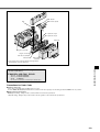
Presenting our CAD drawing
data catalog
VALVES GENERAL CATALOG
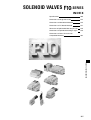
SOLENOID VALVES
SERIES
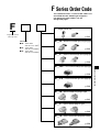
INDEX
Characteristics
Product Range
Table of Cylinder Operating Speed
Operating Principle and Symbol
Handling Instructions and Precautions
Disassembly Diagram and Unit
Adding Procedure
Product Configurations for Serial
Transmission Compatible Manifold
Specifications of Serial Transmission
Compatible Manifold
Precautions for Use Due to Partial
Specification Change
Order Code
Solenoid Valves F10 Series
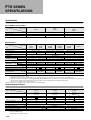
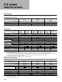
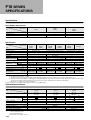
Specifications
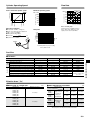
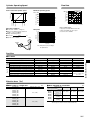
Dimensions
Solenoid Valves F15 Series
Specifications
Dimensions
Solenoid Valves F18 Series
Specifications
Dimensions
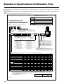
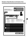
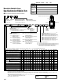
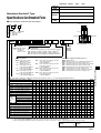
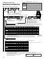
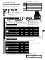
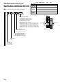
F Series Specifications Confirmation Form
506
508
510
511
512
518
525
526
528
531
567
568
572
585
586
590
603
604
608
619
505
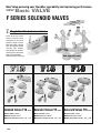
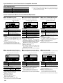
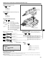
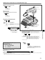
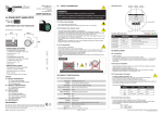
New Valve pursuing user friendlier operability and improving performance
NEW
Basic VALVE
F SERIES SOLENOID VALVES
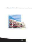
1.
alve
ange v
Can ch on-site!
n
o
functi
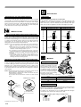
Single/double dual-use valves
The F Series 2-position
valves’ function can be
switched back and forth
between single solenoid
valve and double solenoid
valve by using the manual
override. This enables
using models can be intensified against diversified
application requirement.
Two types in one!
Note: Excluding T0 (T-Zero) type
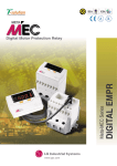
Solenoid Valves F10 Series Solenoid Valves F15 Series Solenoid Valves F18 Series
●Valve width: 10mm
●Effective area: 5mm2
●Applicable cylinder bore sizes: φ20∼φ50
506
●Valve width: 15mm
●Effective area: 10mm2
●Applicable cylinder bore sizes: φ40∼φ80
●Valve width: 18mm
●Effective area: 18mm2
●Applicable cylinder bore sizes: φ50∼φ100
2.
Uses dual-use fittings for different tube sizes.
Allows tubes of different outer diameter to be connect-
ed.Series
F10
F15
Applicable tube sizes
φ4, φ6
φ6, φ8
φ8, φ10
F18
Note: Single size fittings can also be
selected.
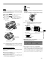
3.
More compact, and high flow rate
Flow rate up by
2~3.3 times with
the same valve
width (compared
with Koganei
product).
Solenoid valves
110 series
15
Solenoid valves
F15 series
Effective area
Effective area
4.0mm
10mm
2
A B
2
15
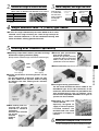
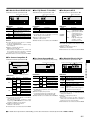
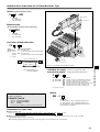
4.
Single solenoid valve T0 (T-zero) type added
●A valve for single solenoid only has been added to the F series
solenoid valve range inheriting the same design concept for
easier selection. Moreover, it can be combined mounting with
earlier manifolds, offering good maintenance.
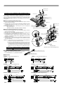
5.
Offering user friendlier operability
●Replacing output blocks make it possible to change
between base piping and direct piping.
●(Except monoblock manifold F type and PC board manifold F type)
●External pilot specification
also can be selected.
External pilot (positive pressure)
specification allows to operate from
0 MPa as main pressure. Vacuum
specification can also be selected.
P2 port
[]
(Base piping)
(Direct piping)
●Female thread block and fitting blocks can be
selected.
For the fitting block, a fitting for single size only
has been added to the previous dual-use fitting
for different size tube, offering easier selection
and usage.
Single size fitting
block-FJ6
Single size fitting
block-FJ5
Dual-use
different size
fitting block
● Both locking and nonlocking type manual
override is standard
equipment.
A manual lever override
can also be
Manual lever
selected.
override
(made to
order)
Female
thread
block
Manual override
●Full range of wiring specifications.
●The PC board manifold has been added to the
monoblock type. A flat cable connector, D sub
connector and terminal block are provided for the
split manifold plug-in type. In addition, serial
transmission compatible manifolds to 12 types of
systems are also available.
●Individual air supply and
exhaust offered.
●Specially designed air
supply or exhaust spacers
installed between the
manifold and valve allow
individual air supply or
exhaust.
6.
Achieves power consumption of 0.9W (Current 38mA, DC24V)
※Power consumption per one valve (for DC24V specification)
507
SOLENOID VALVES F SERIES
●Shared connectors (Single valve unit can also be used as plug-in type).
]\
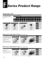
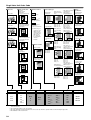
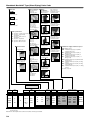
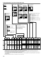
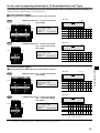
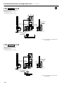
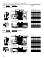
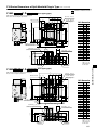
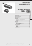
F Series Product Range
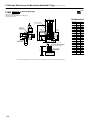
Single Valve Unit
Valves can be used as a single
unit by attaching an input port
block. Mounting brackets are also
provided.
Output port specifications
With sub-base
Series
Female thread
Rc 1/8
F10
●
F15
●
Rc 1/4
F18
With fitting block
With female thread block
For single valve unit or manifold use
With female thread block With different size fitting block
M5
Rc 1/8
Rc 1/4 φ4,φ6 φ6,φ8 φ8,φ10
φ6
●
●
●
●
●
●
●
With single size fitting block
φ4
With A type sub-base
●
●
●
■With mounting bracket
φ8
φ10
●
●
●
Order code p.532,533
F10series p.572
dimensions
F15series p.590
dimensions
F18series p.608
dimensions
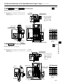
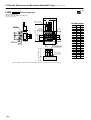
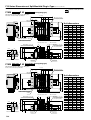
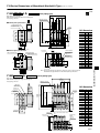
Monoblock Manifold A Type
This base piping type manifold
offers both maintenance and
cost performance. Replacing
the output block enables to use
as a direct piping type
manifold.
Using a plug connector with
common terminal pre-wiring
greatly reduces wiring work.
With fitting block
With female thread block
■Common terminal prewiring plug connector
Order code p.534,535
F10series p.575
dimensions
F15series p.593
dimensions
F18series p.611
dimensions
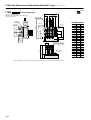
Monoblock Manifold F Type
Manifold for direct piping type
offers excellent cost
performance.
Using a plug connector with
common terminal pre-wiring
greatly reduces wiring work.
(Base Piping Type)
With fitting block
(Direct Piping Type)
With female thread block
■Common terminal prewiring plug connector
Order code p.536,537
F10series p.576
dimensions
F15series p.594
dimensions
F18series p.612
dimensions
508
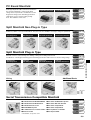
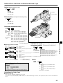
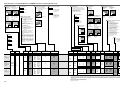
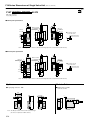
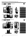
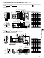
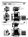
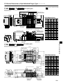
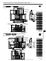
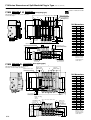
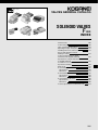
PC Board Manifold
A MIL type 20-pin flat cable connector is mounted on
the monoblock manifold, to achieve both wiring
savings and cost performance. Combined use of the
Koganei PC wiring system and wiring specification
-F201 allows for more effective wiring savings.
Note: Not available for F18 series.
A type (Base piping type)
F type (Direct piping type)
Order code p.538∼541
F10series p.577
dimensions
F15series p.595
dimensions
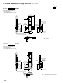
Split Manifold Non-Plug-in Type
Enables easy addition or removal of manifold blocks. This system offers more flexibility in conforming to changes in specifications.
Manifold port
with fitting block
Valve port
with fitting block
Manifold port
with female thread block
Valve port
with female thread block
Order code p.542∼545
F10series p.578
dimensions
F15series p.596
dimensions
F18series p.613
dimensions
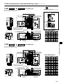
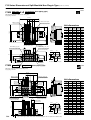
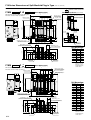
Split Manifold Plug-in Type
Manifold port
with fitting block
Valve port
with fitting block
Manifold port
with female thread block
Valve port
with female thread block
Order code p.546∼549
F10series p.579
dimensions
F15series p.597
dimensions
F18series p.614
dimensions
Wiring
■Flat cable connector
Additional Parts
■D sub connector
■Terminal block
■Muffler
Dimensions
F10 : p. 583
F15 : p. 601
F18 : p. 618
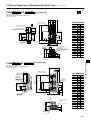
Serial Transmission Compatible Manifold
●For Mitsubishi Electric MELSECNET/MINI-S3
●For Omron SYSBUS Wire System
●For Mitsubishi Electric MELSEC I/O Link
●For Omron B7A Link Terminal
●For Mitsubishi Electric CC-Link
●For Omron CompoBus/D
●For UNI-WIRE® System
●For Omron CompoBus/S
●For KOYO Electronics Industries SA Bus ●For Fuji Electric T Link Mini
●For Sunx S-Link
●For Keyence KZ-R
Order code p.550∼556
F10series p.582
dimensions
F15series p.600
dimensions
F18series p.617
dimensions
※For details, see p. 525∼527.
509
SOLENOID VALVES F SERIES
Manifold conforms to reduced wiring work. Adding on wiring allows adding manifold units.
Combined use of the Koganei PC wiring system and wiring specification -F201 offers more effective wiring savings.
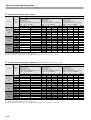
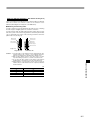
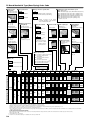
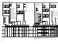
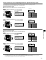
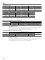
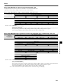
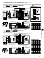
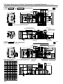
Table of Cylinder Operating Speed
1. Cylinder mounting direction : Vertical
Cylinder series/Conditions/Cylinder bore size mm
Slim Cylinder Series
NEW Pen Cylinder Series
Cylinder
Series
speed
mm/s
Pressure : 0.5MPa
Load ratio : 50%
Cylinder stroke : 150mm
Piping (outer diameter × inner diameter ×
length) : φ6×φ4×1000mm
10
150
F10 series
300
Effective area
450
5mm2
600
16
20
F15 series
300
Effective area
450
10mm2
600
F18 series
300
Effective area
450
18mm2
600
32
40
50
※
63
80
100
★
★
※
※
★
★
★
★
★
750
150
25
Pressure : 0.5MPa
Load ratio : 50%
Cylinder stroke : 150mm
Piping (outer diameter × inner diameter ×
length) : φ10×φ7.5×1000mm
※
750
150
NEW DYNA Cylinder Series
Pressure : 0.5MPa
Load ratio: 50%
Cylinder stroke : 150mm
Piping (outer diameter × inner diameter ×
length) : φ6×φ4×1000mm
※
※
★
★
750
★ : Use each cylinder type within their operating speed range.
※ : Cylinder speed is limited by the connection port orifice size.
Remark : For load ratio of other than 50%, see the "Cylinder Operating Speed" in the specifications for each valve.
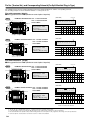
2. Cylinder mounting direction : Horizontal (Roller bearing: Friction coefficient μ=0.1)
Cylinder series/Conditions/Cylinder bore size mm
Slim Cylinder Series
NEW Pen Cylinder Series
Cylinder
Series
speed
mm/s
Pressure : 0.5MPa
Load ratio : 50%
Cylinder stroke : 150mm
Piping (outer diameter × inner diameter ×
length) : φ6×φ4×1000mm
10
16
NEW DYNA Cylinder Series
Pressure : 0.5MPa
Load ratio: 50%
Cylinder stroke : 150mm
Piping (outer diameter × inner diameter ×
length) : φ6×φ4×1000mm
20
25
32
40
Pressure : 0.5MPa
Load ratio : 50%
Cylinder stroke : 150mm
Piping (outer diameter × inner diameter ×
length) : φ10×φ7.5×1000mm
50
63
80
150
F10 series
300
Effective area
450
5mm2
600
※
※
★
★
750
★
150
F15 series
300
Effective area
450
10mm2
600
※
※
★
750
150
※
※
F18 series
300
Effective area
450
18mm2
600
750
★
★
★
★
★
★ : Use each cylinder type within their operating speed range.
※ : Cylinder speed is limited by the connection port orifice size.
Remark : For load ratio of other than 50%, see the "Cylinder Operating Speed" in the specifications for each valve.
510
★
★
★
★
※
★
★
★
100
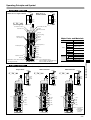
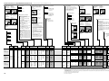
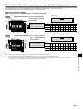
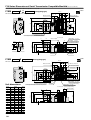
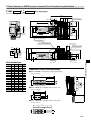
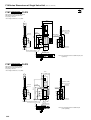
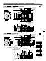
Operating Principle and Symbol
5-port, 2-position
14
(SA)
When set as a single solenoid
(
4 A)
(
2 B)
14
(SA)
When set as a
double solenoid
(
4 A)
(
2 B)
(
5 R1)
(
1 P)
(
3 R2)
F□T1□-A1
(De-energized)
P2
P2
Note 1
Solenoid
SolenoidA〔14(SA)〕
Solenoid cover
(
5 R1)
(
1 P)
(
3 R2)
Note 1
12
(SB)
B〔12(SB)〕Note 3
Column
Molded solenoid
Plunger
Plunger spring
Flapper
Piston
Major Parts and Materials
Lip seal
Parts
PR
P2 External pilot Note 1
Sub-base
1(P)
Plunger
2(B)
Column
End cover
3(R2)
Stem
Manifold
Valve body
Synthetic rubber
Aluminum alloy (anodized)
Magnetic stainless
Plastic
Monoblock Aluminum alloy (anodized)
Split type
Plastic
Block-off plate Steel (nickel plated)
Notes: 1. For external pilot type
2. Not available in external pilot type
3. Not available with T0 type
※Illustration shows when setting as
※the single solenoid.
Aluminum alloy
Flapper
Valve
4(A)
End cover
Stem
Lip seal
5(R1)
Manual override Note 3
Aluminum die-cast
Seal
Synthetic rubber
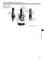
5-port, 3-position
〔Both 14 (SA) and 12 (SB) are de-energized〕
All port block
ABR connection
14
(SA)
F□T3□-A1
F□T4□-A1
(
4 A)
(
2 B)
Note 1
P2
P2
12
(SB)
P2 Note 1
Note 2
5(R1)
(
4 A)
(
2 B)
(
5 R1)
(
1 P)
(
3 R2)
Note 1
P2
12
(SB)
PR
Note 1
P2
PR
Note 2
14
(SA)
F□T5□-A1
(
4 A)
(
2 B)
(
5 R1)
(
1 P)
(
3 R2)
PAB connection
14
(SA)
5(R1)
(
5 R1)
(
1 P)
(
3 R2)
Note 1
12
(SB)
PR
P2 Note 1
Note 2
5(R1)
4(A)
4(A)
4(A)
1(P)
1(P)
1(P)
2(B)
2(B)
2(B)
3(R2)
3(R2)
3(R2)
Notes: 1. For external
pilot type
2. Not available
in external
pilot type
511
SOLENOID VALVES F SERIES
Internal pilot Note 2
Materials
Body
Body
Manual override
Pilot valve body
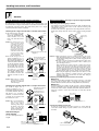
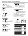
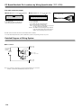
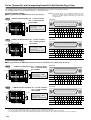
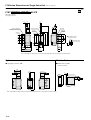
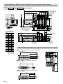
Handling Instructions and Precautions
Solenoid
Single and double solenoid switching procedure
Wiring instructions (When using as a single unit, non-plug-in type manifold)
By switching the manual override, model F□T1(2-position valve)can
be used as either a single solenoid valve or a double solenoid valve (not
possible with 3-position valve). Note that the F □T1 is set to single
solenoid specification at time of delivery.
Switching from a single solenoid valve to a double solenoid valve
1.As shown in Fig.1, insert the
Convex section
Pin
Claw
Caution: As shown in Fig.1, be
sure to insert a small
screwdriver from the
side of the valve cover.
The cover claw may be
damaged when the
cover is removed from
the direction of the valve
stem. Never remove the
cover for any reason
other than the valve
function switching.
Lever
Housing
Convex section
※Illustration shows the F10 series.
Plug connector
Pin
Contact
〔Figure 1〕
2. As shown in Fig. 2, use a
Turn the manual override
in a counterclockwise
direction for setting double
solenoid.
B side manual override
Single solenoid state
Double solenoid state
The manual
override is
protruding.
Caution: When using as a double
solenoid valve, do not
attach the cover that was
removed in Fig. 1.
〔Figure 2〕
Switching from a double solenoid valve to a single solenoid valve
As shown in Fig. 3, use a
small screwdriver, etc., to
push lightly against the manual override, and then turn it by
90 degree in a clockwise
direction, so that the manual
override slit is vertical, and
then attach the cover.
Caution: The cover has directionality (F15 and F18
series only). When
attaching, always align
the detent on the back
of the cover with the
manual override button’s
slit, as shown in Fig.4.
Use fingers to insert the connector into the pin, push in until the lever
claw catches on the convex section on the connector housing, and
complete the connection.
To remove the connector, squeeze the lever along with the connector,
lift the lever claw up from the convex section on the housing, and pull
out.
Housing
Cover
tip (−) of a small screwdriver into the gap between the
valve and the cover, and
peel it off and remove the
cover.
small screwdriver, etc., to
turn the manual override on
the B side by 90 degree in a
counterclockwise direction,
so that the manual override
slit is horizontal, as shown
on the right side of the figure, then the unit can now
be used as a double
solenoid valve. When using
as a double solenoid valve,
the override is used as the
manual override for the B
side.
1.Attaching and removing plug connector
Push lightly, then turn the
manual overrride in a
clockwise direction for
setting single solenoid.
Lead wire (White)
Cautions: 1.When removing the connector, confirm that the lever claw is positively disengaged from the convex section before pulling out. The
housing may be damaged if it is pulled out while engaging with the
convex section.
2.The plug connector lead wires for model F□T1 (2-position valve)
are set to single solenoid specification at time of delivery. (For
types with plug connector)
2.When switching from a single solenoid to a double solenoid specification for use, disconnect the plug connector from the valve,
check the hook directions on the lead wire (white) with contacts,
and then insert the lead wire into the plug connector's B side□
hole (see illustration above). Use the same procedure to switch
the manifold type single solenoid to double solenoid specification.
3.When using the plug-in type manifold, be aware that even if the
valve has been switched to a double solenoid, no power will be
supplied to the B side solenoid unless the valve base wiring are
set to the double wiring.
2.Attaching and removing plug connector and contact
●Attaching
Insert the contact with a lead wire into a plug connector □ hole until
the contact hook catches and is secured to the plug connector.
Confirm that the lead wire cannot be easily pulled out. (See below)
●Removing
To remove, insert a tool with a fine tip (such as a small screwdriver)
into the rectangular hole on the side of the plug connector to push up
on the hook of the contact, and then pull out the lead wire. When reusing the contacts, restore the hook back so that they spread
outward.
Plug connector
Manual override
Hook
Contact
Double solenoid state
Single solenoid state
The manual
override is
protruding.
Note about wiring for
above switching
〔Figure 3〕
Lead wire
3.Common terminal and short bar
A short bar is attached to the plug connector to ensure that the
solenoid A and B wiring are plus common. Do not remove the
short bar.
Cover
(Back face)
See the "Wiring instructions"
at right.
Detent
End cover
Manual overrride
〔Figure 4〕
512
Indication of polarity(DC)
Short bar
Contact(without lead wire)
4.Crimping of connecting lead wire and contact
Internal circuit
To crimp lead wires into contacts, strip off 4mm of the insulation from
the end of the lead wire, insert into the contact, and crimp it. Be sure
to avoid catching the insulation on the expose wire crimping section.
Voltage
specification
Internal circuit
(Inside of the connector)
Insulation crimp tab
Expose wire 4mm
Expose wire crimping section
(Color of lead wire: Black)
A
(Red)
Lead wire
Applicable wire
AWG#24∼#30
Contact
Hook
Insulation
(Maximum outer diameter:φ1.5)
14
(SA)
DC24V
DC12V
(Color of lead wire: Red)+COM
12
(SB)
(Green)
Cautions: 1. Do not pull hard on the lead wire.
2. Always use the dedicated tool for crimping of connecting lead wire
and contact.
Contact: Model 706312-2MK Manufactured by Sumiko Tech, Inc.
Crimping tool: Model F1 (For 706312-2MK) Manufactured by Sumiko
Tech, Inc.
(Color of lead wire: White)
B
(Inside of the connector)
(Color of lead wire: Black)
(Red)
A
14
(SA)
5.Common connector assembly for manifold
Using common connector assembly for the solenoid valve for manifold
provides common wiring for all solenoid valves and greatly reduces
wiring work.
AC100V
(Color of lead wire: Red) COM
(Color of lead wire: White)
Single solenoid valve
B
(Green)
12
(SB)
Double solenoid valve
Common wire(+)
Common wire(+)
Common wire(+)
)
C type
BA
BA
A
―
A(
〔Figure 5〕
―)
(
Cautions: 1. Do not apply megger between the pins.
2. For switching wiring between a single solenoid and a double
solenoid, see the "Wiring instructions" item on p. 512.
3. Common wiring set for double solenoid in DC specification is
plus common specification.
4. Leakage current inside the circuit could result in failure of the
solenoid valve to return to the rest position or in other erratic
operation. Always use at less than the allowable leakage current
shown in the solenoid specifications on p. 568, 586, and 604. If
circuit conditions, etc., cause the leakage current to exceed the
maximum allowable leakage current, consult us.
5. For the double solenoid specification, avoid energizing both
solenoids simultaneously.
6.Common connector assembly (plus common specification)
If wanting to add units after mounting to the connector assembly for
manifold, order the common connector assembly shown below.
A type Model:FZ-PA□※
Red Common wire (+)
Black A side (−)
White B side (−) (Insert when using as a double solenoid)
B type Model:FZ-PB□※
C type Model:FZ-PC□※
Red Common wire (+)
Black A side (−)
White B side (−) (Insert when using as a double solenoid)
Red
Black
White
Red
Note:FZ0-P□□ has no white wires.
Common wire (+)
A side (−)
B side (−) (Insert when using as a double solenoid)
Common wire (+) ※: Lead wire length Blank: 300mm
3: 3000mm
The common connector types are determined by looking from the
lead wire side, the right end one is A type, the left end one is C type,
and all others are B type. (see Fig. 5)
7.Cabtire cable
φ4.2
CC1.5:1500mm CC3:3000mm
(32.2)
Connector
PC board manifold
When connecting a power
line to the power supply
terminal on the PC board
manifold, pay attention to
the following points to connect.
Power supply terminal
Terminal screw tightening torque: 0.4N・m {0.04kgf・m}
Stripped wire length: 7mm
Connecting wire size: 0.13∼2.5mm2
AWG: No.26...14
If planning to use pressing terminals, use bar terminals.
Recommended pressing terminals (bar terminals): Manufactured by
Nichifu, Inc.
Model BT1.25-9-1 (for 0.25∼1.65mm2)
Wiring of terminal block
Be aware of the terminal screw tightening torques.
Overtightening beyond the tightening torque could
result in breakage.
Terminal screw tightening torque: Max. 49.0N・cm
{5.0kgf・cm}.
Cap
Caution: Be aware that these are not dust-proof and drip-proof specifications.
513
SOLENOID VALVES F SERIES
B type
A type
Valve function
3-port valves
Manual override
Manual override (both locking and non-locking type)
To lock, use a small screwdriver to push down on the manual override
all the way down and turn it clockwise 90 degrees. When locked, turning
the manual override 90 degrees in a counterclockwise direction, releases a spring on the manual override, returns it to the original position and
releases the lock. To operate the unit in the same way as the nonlocking type, leave the manual override unturned.
Cautions: 1. The F series are pilot type solenoid valves. As a result, the manual override cannot switch the main valve without supplying air from the P(P2)
port.
2. Always release the lock on the manual override before commencing normal operation. For details (excluding the 3-position valve), see the "Single
and double solenoid switching procedure" on p. 512.
3. Do not attempt to operate the manual override with a pin or other object
having an extremely fine tip. It could damage the manual override button.
4. Take care to avoid excessive turning of the manual override, which could
damage it.
5. If operating the solenoid valve's manual override for maintenance, etc.,
always confirm that the solenoid valve's override button has been
restored to its original state, and that the main valve is in the necessary
switching position before restarting operations.
When using the 5-port valve as a 3-port valve
In the F10, F15, and F18 series, plug one of the output ports (A or B)
enabling to use as a normally closed (NC) or normally open (NO) 3-port
valve. In this case, leave the exhaust ports (R1 and R2) in the open
status. This can also be applied to a double solenoid-type 3-port valve.
Plug position
Plug the B port
Plug the A port
Switching type
Normally closed(NC)
Normally open(NO)
For single solenoid setting
When using models F □T1 or F □T2 (2-position valve) as double
solenoid valves, be aware that energizing the A side solenoid or pushing
the manual override on the A side while in a locked state, while energizing the solenoid on the B side, or while pushing the B side manual override, cause the valve to switch over. (At this time, the valve will operate
as the same state as for the single solenoid valve.)
For double solenoid setting
Precautions for use of the double solenoid
To lock, use fingers to push down on the lever all the way down and turn
it clockwise 90 degrees. When locked, turning the manual lever override
90 degrees in a counterclockwise direction, releases a spring on the
manual override, returns it to the original position, and releases the lock.
To operate the unit in the same way as the non-locking type, leaving the
lever unturned.
Caution: Model F□T1 (2-position valve) has a manual lever override on the A
side and a manual override (with cover) on the B side.
Model F□T2 has a manual lever override on the A side only, and a
manual override on the B side.
The 3-position valve has manual lever override on both the A and B
sides.
(
4 A)
(Plug)(
2 B)
14
(SA)
(Plug)(
4 A)
(
5 R1)
(
1 P)
(
3 R2)
(
2 B)
14
(SA)
(
4 A)
(Plug)(
2 B)
(
5 R1)
(
1 P)
(
3 R2)
14
(SA)
(
5 R1)
(
1 P)
(
3 R2)
(
4 A)
(Plug)
(
2 B)
12
(SB)
(
5 R1)
(
1 P)
(
3 R2)
12
(SB)
Manifold
Manual lever override (both locking and non-locking type)
(made to order)
14
(SA)
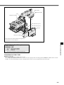
Attaching and removing valves
To remove the valve body from the
sub-base or manifold, loosen the
valve mounting screws (2 places),
and lift up in the direction of the arrow
(see diagram at right). For mounting,
conduct the same procedure in
reverse. The recommended tightening torques for the valve mounting
screws are as shown below.
※Illustration shows the F10 series. (split manifold)
Series
Manual lever override
N・cm{kgf・cm}
Recommended tightening torque
F10
17.6 {1.8}
F15
49.0 {5.0}
F18
49.0 {5.0}
TURN
Sub-plate (service part)
A side manual
override
PUSH
B side manual override
A sub-plate is provided as a service part required for mounting new type
valves on the earlier type of split manifold plug-in type, and the earlier
type of serial transmission compatible manifold.
For details, see "Precautions for Use of Partial Specification Changes
(for Deliveries after January 30, 1997)"(p. 528∼529).
Sub-plate
F
(sub-plate, gasket, O ring, 2 mounting screws)
Z-S
Valve size
10:10mm width
15:15mm width
18:18mm width
※Illustration shows the F10 series.
514
Fitting
Split
Piping
In the split manifold, inserting splits to the P and R ports between each
of the stations isolate the air path between stations equipped with splits
and stations with smaller station numbers. Note, however, that a piping
block must be placed on both ends.
●Splits for the P port
(Mode : F□Z-SP)
Can supply two different pressures.
●Splits for the R port
(Model : F□Z-SR)
Can isolate exhaust air .
(prevents exhaust interference)
●Splits for the P and R ports
(Model : F□Z-SA)
Can supply two different pressures,
and can isolate exhaust air.
(prevents exhaust interference)
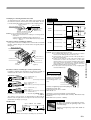
1. Procedure for replacing the base piping type and the direct
piping type
Base piping and direct piping re-combinations can be done by replacing the plate with a fitting block or a female thread block. (see Fig. 6).
A port
B port
Fitting block
Plate
B port
A port
※□ denotes valve size.
Plate
〔Figure 6〕
〔F10, F15 series〕
※Illustration shows the F10 series.
SP: Split for
the P port
Cautions: 1. Firmly tighten the screws after completing a re-combination.
2. Conduct piping carefully in regards to the positions of each connection port (see Figs. 7, 8).
3. Be careful about losing the gaskets while conducting plate
replacement.
● Direct piping type
For F10, F15 series
For F18 series
A B
A B A B A B A B A B
P port
A port
B port
A B
A B
A B
A B
R port
A port
Note
P port
B port
R port
Note
SR: Split for the R port
〔Figure 7〕 Note: Be aware that the positions of the
P and R ports are reversed from
the positions in the F10 and F15
series.
〔F18 series〕
● Base
piping type
Port positions for F10, F15, F18 series are as shown in Fig. 8.
P port
B port
A port
R port
〔Figure 8〕
SP: Split for the P port
※Illustration shows the F10 series.
2. Attaching fittings to female thread blocks
SR: Split for the R port
Caution: Mounting splits requires the disassembly and re-assembly of manifolds. See the disassembly diagram, unit adding procedure, and cautions found on p. 518∼523.
Note, however, that since the F18 series serial transmission compatible manifold cannot be disassembled, splits cannot be mounted later.
When attaching fittings to female thread blocks, fasten with the
tightening torques shown below or less.
Screw size
Tightening torque N・cm {kgf・cm}
Rc 1/8
686 {70}
Rc 1/4
882 {90}
※For M5, attach at the torques recommended for the fittings.
3. Attaching fittings to piping blocks〔F18Z(G)-PM(P)〕
Precautions for using manifold
Observe the following precautions when using the split type and serial
transmission compatible manifold. (Except monoblock manifold and PC
board manifold)
To attach fittings to the female thread type piping block of the F18
series, remove the piping block section (the triangular-shaped block
section), use a spanner to the metallic sections of both the P and R
ports to fix them in place, and then screw in the fittings.The tightening
torque for the mountings (two M3 screws) of the piping block section
after the fittings have been attached should be 49.0 N・cm {5.0kgf・cm}.
●When using the direct piping type
Avoid valve use at an operating frequency exceeding 2Hz, as such
use can result in heat-related breakdowns.
●When using the base piping type
When plugs have been attached either or both on the A and B ports,
avoid valve using at an operating frequency exceeding 2Hz, as such
use can result in heat-related breakdowns.
515
SOLENOID VALVES F SERIES
※Illustration shows the F10 series.
Mounting screw
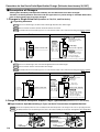
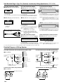
Precautions for use of individual air supply and exhaust spacers
Exhaust valve
Gasket
By mounting an independent air supply or exhaust spacer on the manifold, air supply or exhaust can be operated individually on the unit. Note
that when spacers are used, the effective area is reduced by about
30%. If mounting additional spacers to an existing unit, observe the following items.
Individual air supply and
exhaust spacer
●Spacer mounting method (F10 series)
q Loosen the valve mounting screws for the individual air supply or exhaust
spacer, and remove the valve.
w Install the gaskets and exhaust valve provided with the individual air supply
or exhaust spacer, use the mounting screws provided to fix the valve on
the manifold. (see Fig. 9)
Remark: When attaching fittings to the F10 spacer, use the recommended
fittings shown below.
Remark: TSH4-M5M, TSH4-M5, TSH6-M5M, TS4-M50, TS4-M5M
〔Figure 9〕
Mounting screw
Cover
Color: Light blue
F10 series
(Illustration shows the split manifold plug-in type)
Gasket
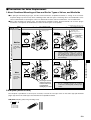
●Spacer mounting method (F 15, 18 series)
q Loosen the valve mounting screws for the individual air supply or exhaust
spacer, and remove the valve.
w Open the cover of the manifold, and pull out the plug-in connector in the
forward direction. (For the plug-in type) (see Fig. 10)
e Insert the plug-in connector firmly into the connector attaching section of
the individual air supply or exhaust spacer, and then close the cover, while
watching to ensure that lead wires are not caught with the cover. (For the
plug-in type) (see Fig. 11)
r Attach the gasket and exhaust valve provided with the individual air supply
or exhaust spacer, and use the mounting screws provided to mount the
valve on the manifold.
Cautions: 1. Locations where the spacers are mounted make the valve height higher by
the height of the spacer. (See the dimensions below)
2. The F series split manifold plug-in type, and the serial transmission
compatible manifold, have undergone partial specification changes, with the
result that earlier and new types exist. A change in the shape of the connector receptacle means that it cannot be mounted on the earlier type manifold.
Use the color of the cover to identify the new or earlier types (see Figs. 9
and 10).
Type
Item
Color of cover
Earlier type of manifold
Ivory
Exhaust valve
Plug-in connector
Plug-in connector
Figure 11
〔Figure 10〕
Cover
Color: Light blue
F15,18 series
(Illustration shows the split manifold plug-in type)
New type of manifold
Light blue
●Muffler for individual exhaust spacer
Muffler for individual exhaust spacer
Muffler for the independent exhaust spacer is provided.
For outer dimensions, see p. 583, 601, and 618.
Individual exhaust spacer
●Dimensions
F10Z-N□ □ (For F10 series) Mass 7g
F10Z-P□ □ (For F10 series) Mass 9g
M5×0.8
58.5
95.3
10
10
M5×0.8
9
9
Valve side
Manifold side
F15Z-N□ □ (For F15 series) Mass 26g
F15Z-P□ □ (For F15 series) Mass 29g
9.4(φ6, φ8)
Fitting(φ6, φ8)
13
16
13
16
Fitting(φ6, φ8)
F18Z-N□ □ (For F18 series) Mass 41g
F18Z-P□ □ (For F18 series) Mass 44g
9.4(φ8)
17.5(φ10)
18.8
103.5
18.8
9.4(φ8)
Fitting(φ8, φ10) 17.5(φ10)
13
18
13
18
Fitting(φ8, φ10)
516
129.5
15.8
90.5
15.8
9.4(φ6, φ8)
Individual air
supply and
exhaust spacer
142.5
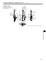
Dual-use different size fitting
(With different size fitting block)
The F series different size fitting blocks use dual-use fittings for different
tube sizes, which can connect to tubes of two different outer
diameter. (Excluding the P and R ports of the F18 Series)
●Attaching and removing tubes
For tube connection, insert an appropriate size tube as far as contacting
the tube stopper, and lightly pull on it to check the connection.
For tube removal, push the tube against the tube stopper, then for large
tube sizes, push on the release ring and at the same time pull the tube
out. For small tube sizes, push on the outer ring and at the same time
pull the tube out. (See Fig. 12)
Release ring
Tube stopper
Release ring
Outer ring
Tube stopper
〔Figure 12〕
Large tube size
Small tube size
SOLENOID VALVES F SERIES
Cautions: 1. Use tubes with an outer diameter tolerance within ±0.1mm of the
nominal diameter, and a degree of out-of-ellipticity (difference
between long diameter and short diameter) is 0.2mm or less.
2. Only use tubes without scratch is on the outer surface. If scratch
is produced during repeated use, cut off the scratched section.
3. Do not bend the tube sharply near the fittings. The minimum
bending radius for nylon tubes is as shown in the table below.
4. When attaching or removing tubes, always stop air supply. In
addition, always confirm that air has been completely exhausted
from the manifold.
mm
Tube size
Minimum bend radius
φ4
20
φ6
30
φ8
50
φ10
80
517
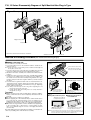
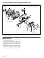
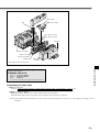
F10, 15 Series Disassembly Diagram of Split Manifold Non-Plug-in Type
Figure 1
Fixing screw
End block
Disassembly example: For F10 series
Piping block assembly
Release lever
Note: The F series has the same basic construction.
Valve base assembly
End block
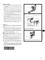
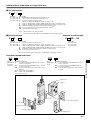
Manifold Unit Adding Procedure (F10 and F15 Series Non-Plug-in Type)
■Adding valve base unit
Use the valve base assembly to add units.
q Loosen the fixing screw on the end block until the end block can
slide (see Fig. 1).
Figure 2
First let the hook catch on this
side, and then press down on
the base to fit it into the DIN rail.
Note: For the 15 series, loosen the fixing screws on both the left and right end
blocks (three screws each).
w Press the release lever on the valve base assembly where the new
unit is to be added, and disconnect the link between the bases.
e Mount the valve base assembly to be added on the DIN rail shown
in Fig. 2.
r Return the release lever of the valve base assembly disassembled
in Step w to its original position, as shown in Fig. 3. In addition, set
the release lever for the valve assembly being added to the same
position, then press the bases together until they connect and click
into place.
t Press the bases together from both sides to ensure that there is no
gap between them, and then tighten the end block fixing screws,
and mount the units in place on the DIN rail (see Fig. 5). Tightening
torque: 128N・cm {13kgf・cm}
Notes: 1. Always follow the steps shown in Fig. 4 when tightening the end
block fixed screws for the F15 series.
2. Confirm that the DIN rail mounting hooks are securely attached to
the DIN rail. (see Fig. 5).
【Caution】
●Always cut off the power and air supply before working. In addition,
always confirm that air has been completely exhausted from the
manifold.
●Be careful not to be caught or lose gaskets.
●Before supplying air to the manifold, always confirm that the bases
are connected, the end block fixing screws are tightened, etc.
Supplying air when either of the end blocks are not securely fixed to
the DIN rail could result in air leaks or in separated manifold bases.
●When there are large number of valves simultaneously supplying air
to the secondary side, or when there is a large number of valve
units, we recommend using two sources of air supply and exhaust
(on each side).
Note that adding units of the piping block assembly is conducted in the
same way as adding units of the valve base assembly.
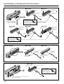
Figure 3
Figure 4
●Tightening order of screws(for F15 series only)
A B
A B
A B
3
1
4
Pressing down lightly on
the release lever will return
it to its forward position.
Figure 5
●Fixing the end block in place
Tighten the screw with the
L-shaped hook pushed in.
5
2
6
Always tighten the middle fixing screw of
each end block first.
Tightening torque: 128N・cm {13kgf・cm}
●Removing the end block
from the DIN rail
w
DIN rail
Use hooks on both sides to
fix the DIN rail in place.
q
For mounting, follow in reverse
the steps taken for removal.
Caution: The new end block for the F10 series does not include an L-shaped hook. To
remove the end block from the DIN rail, loosen the end block fixing screws, and lift
it off. (The switch to the new type will commence in October 2000)
518
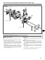
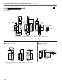
F18 Series Disassembly Diagram of Split Manifold Non-Plug-in Type
Figure 1
Connecting bolt
End block
Piping block assembly
Valve base assembly
End block
Manifold Unit Adding Procedure (F18 Series Non-Plug-in Type)
■Adding valve base unit
Use the valve base assembly and unit-adding connecting rod to add
units.
q Remove the connecting bolts on the end block and separate the
end block from the manifold (see Fig. 1).
w Install the connecting rods to be added, open up spaces where the
units are being added, fit gaskets into the valve base assemblies
being added, and place the units on top of the connecting rods. At
this time, securely mount so that no space is left between the
added valve base assemblies and the upper surface of the
connecting rods.
e Fit gaskets into the end blocks removed in Step q, and retighten the
connecting bolts. At this time, use a hexagonal bar wrench to hold
the connecting bolts on the opposite side in place so as to prevent
the bolts from slipping while tightening them into place. Tightening
torque: 147N・cm {15kgf・cm}
【Caution】
●Always cut off power and air supply before working. In addition,
always confirm that air has been completely exhausted from the
manifold.
●Be careful not to be caught or lose gaskets.
●Before supplying air to the manifold, always confirm that the bases
are securely connected, the end block connecting bolts on both
sides are tightened, etc. Supplying air when either of the end blocks
is not securely fixed in place could result in air leaks or in separated
manifold bases.
●When there are large number of valves simultaneously supplying air
to the secondary side, or when there is a large number of valve
units, we recommend to use two sources of air supply and exhaust
(on each side).
Note that adding units of the piping block assembly is conducted in the
same way as adding units of the valve base assembly.
519
SOLENOID VALVES F SERIES
Connecting rod
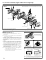
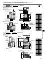
F10, 15 Series Disassembly Diagram of Split Manifold Plug-in Type
Fixing screw
Figure 1
End block
Disassembly example: For F10 series (using flat cable connector)
Additional side
Piping block assembly
Additional
position
Release lever
Cover
Valve base assembly
Note: The F series has the same basic configuration.
Wiring block assembly
End block
Manifold Unit Adding Procedure (F10 and F15 Series Plug-in Type)
■Adding valve base unit
Figure 2
Use the valve base assembly to add units.
q Loosen the fixing screw on the end block until the end block can
slide (see Fig. 1).
First let the hook catch on this
side, and then press down on
the base to fit it into the DIN rail.
Note: For the F15 series, loosen the fixing screws on both the left and right
end blocks (three screws each).
w Add units on the side shown in Fig. 1 (with the solenoid on top and
the right). To split up at additional unit location, push the piping
base assembly's release lever, and release the connections
between bases.
e Mount the valve base assembly to be added on the DIN rail shown
in Fig. 2.
r Return the release lever of the piping block assembly disassembled in
Step w to its original position, as shown in Fig. 3. Put the release
levers on the additional valve bases in the same position, and press
all the bases together until they click into place, all the while watching
to ensure that lead wires are not caught by the cover.
t Press the bases together from both sides to ensure that there is no
gap between them, and then tighten the end block fixing screws,
and fix the units in place on the DIN rail (see Fig. 5). Tightening
torque: 128N・cm {13kgf・cm}
Notes: 1. Always follow the steps shown in Fig. 4 when tightening the
end block fixing screws for the F15 series.
2. Confirm that the DIN rail mounting hooks are securely
attached to the DIN rail. (see Fig. 5).
Figure 3
Figure 4
●Tightening order of screws(for F15 series only)
A B
A B
A B
3
1
4
Pressing down lightly on
the release lever will return
it to its forward position.
Figure 5
●Fixing the end block in place
Tighten the screw with the
L-shaped hook pushed in.
5
2
6
Always tighten the middle fixing screw of
each end block first.
Tightening torque: 128N・cm {13kgf・cm}
●Removing the end block
from the DIN rail
w
DIN rail
Use hooks on both sides to
fix the DIN rail in place.
q
For mounting, follow in reverse
the steps taken for removal.
Caution: The new end block for the F10 series does not include an L-shaped hook.To
remove the end block from the DIN rail, loosen the end block fixing screws, and
lift it off. (The switch to the new type will commence in October 2000)
520
q Use a minus screwdriver to open all of the covers (see Fig. 1). Loosen
the mounting screws of the valves next to the valve bases to be
added, remove the valves, and remove the plug-in connectors. (see
Fig. 6)
w End terminal lead wires (short red wires) are inserted into pin insert
section (No.3) of the plug-in connectors removed in step q. (see
Fig. 7)
(At time of delivery, end terminal lead wire is inserted into the plugin connectors of the end unit valve.) Remove this end terminal lead
wire, and insert it into the insert section (No.3) of the plug-in
connector for the valve base assembly to be added. Next, insert the
common wire (red) of this plug-in connector into the insert section
(No.3) of the removed plug-in connector.
Figure 6
Plug-in connector
Pull straight out
Figure 7
Note: When inserting the lead wire, confirm that the short bar of the plugin connector's common wire insert section has been inserted.
e Install each of the plug-in connectors wired in step w to the valve
base, and mount the valve.
r Remove the wiring block mounting screws and place them in the
position shown in Fig. 8, then connect the lead wire (white) of the
added valve base after confirming the pin location. (For details, see
the detailed diagram of the wiring block internal connections on
p. 524)
t Return the connector brackets to their original position, and tighten
the wiring block mounting screws in place, then close the cover
while watching to ensure that the lead wires are not caught by the
cover.
Newly added plug-in connector
※1
End terminal lead wire (red)
Plug-in connector
Common wire (red)
Lead wire (white)
Common
wire (red)
End terminal lead wire (red)
(Short, red wire)
【Caution】
●Always cut off the power and air supply before working. In addition,
always confirm that air has been completely exhausted from the
manifold.
●When removing lead wires from the plug-in connector, use an item
with a fine tip (such as a small screwdriver) to press lightly on the
contact hook section from a window on the side of the plug-in connector, and pull out the lead wire. If re-inserting the lead wire to the
connector, spread the contact hooks so that they face outward, and
then insert into the plug-in connector. At this time, pull lightly on the
lead wire to confirm that it is securely inserted.
●Always connect the end terminal lead wires. (see Fig. 7).
●Be careful not to be caught or lose gaskets.
●Before supplying air to the manifold, always confirm that the bases
are connected, and the end block fixing screws are tightened, etc.
Supplying air when either of the end blocks are not securely fixed to
the DIN rail could result in air leaks or in separated manifold bases.
●Be aware that the manifold is limited in the number of valve units
that can be added, by the wiring specifications and wiring connection procedures, etc. For details, see the "Table for maximum number of valve units, by wiring specification," on p. 548.
●When there are large number of valves simultaneously supplying air
to the secondary side, or when there is a large number of valve
units, we recommend using two sources of air supply and exhaust
(on each side).
※2
Replace the end terminal lead wires
Lead wire (white)
※2
※1: Always insert end terminal lead wires.
※2: Shows when both A and B are used.
Figure 8
Mounting screw
Connector bracket
See "Detailed Diagram of Wiring Block Internal Connections" on p.524.
Note that adding units of the piping block assembly is performed in
the same way as adding units of the valve base assembly. In addition, when the wiring block and piping block are side-by-side, always
mount the wiring block at the outside of the piping block, for structural reasons.
Valve tightening torque
N・cm {kgf・cm}
Series
Torque
F10
17.6 {1.8}
F15
49.0 {5.0}
521
SOLENOID VALVES F SERIES
■Wiring Procedure
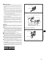
F18 Series Disassembly Diagram of Split Manifold Plug-in Type
Figure 1
Disassembly example: For mounted flat cable connector
Connecting bolt
End block
Additional
side
Additional
position
Piping block assembly
Cover
Valve base assembly
Wiring block assembly
Connecting rod
End block
Manifold Unit Adding Procedure
(F18 Series Plug-in Type)
■Adding valve base unit
Use the valve base assembly to add units.
q Remove the connecting bolts on the end block and separate the
end block from the manifold (see Fig. 1).
w Install the connecting rods to be added, open up spaces where the
units are being added, fit gaskets into the valve base assemblies
being added, and place the units on top of the connecting rods. At
this time, securely mount so that no clearance is left between the
added valve base assemblies and the upper surface of the
connecting rods.
e Fit gaskets into the end blocks removed in Step q, and retighten
the connecting bolts. At this time, use a hexagonal bar wrench to
hold the connecting bolts on the opposite side in place so as to prevent the bolts from slipping while tightening them into place.
Tightening torque: 147N・cm {15kgf・cm}
522
q Use a minus screwdriver to open all of the covers (see Fig. 1).
Loosen the mounting screws of the valves next to the valve bases
to be added, remove the valves, and remove the plug-in connectors. (see Fig. 2).
w End terminal lead wire (short red wire) is inserted into pin insert
section (No.3) of the removed plug-in connectors in step q. (see
Fig. 3)
(At time of delivery, end terminal lead wire is inserted into the plugin connectors of the end unit valve.) Remove this end terminal lead
wire, and insert it into the insert section (No.3) of the plug-in connector for the valve base assembly to be added. Next, insert the
common wire (red) of this plug-in connector into the insert section
(No.3) of the removed plug-in connector.
Note: When inserting the lead wire, confirm that the short bar of the plugin connector's common wire insert section has been inserted.
e Install each of the plug-in connectors wired in step w to the valve
base, and mount the valve.
r Remove the wiring block mounting screws and place them in the
position shown in Fig. 4, then connect the lead wire (white) of the
added valve base after confirming the pin locations. (For details,
see the detailed diagram of wiring block internal connections on
p. 524)
t Return the connector brackets to their original position, and fix the
wiring block mounting screws in place, then close the cover while
observing that the lead wires are not caught by the cover.
Figure 2
Plug-in connector
Pull straight out
Figure 3
Newly added plug-in connector
※1
End terminal lead wire (red)
Plug-in connector
Common wire (red)
Lead wire (white)
Common
wire (red)
End terminal lead wire (red)
(Short, red wire)
【Caution】
●Always cut off power and air supply before working. In addition,
always confirm that air has been completely exhausted from the
manifold.
●When removing lead wires from the plug-in connector, use an item
with a fine tip (such as a small screwdriver) to press lightly on the
contact hook from a window on the side of the plug-in connector,
and pull out the lead wire. If re-inserting the lead wire to the connector, spread the contact hooks so that they face outward, and then
insert into the plug-in connector. At this time, pull lightly on the lead
wire to confirm that it is securely inserted.
● Always connect the end terminal lead wires. (see Fig. 3).
●Be careful not to be caught or lose gaskets.
●Before supplying air to the manifold, always confirm that the bases
are connected, the end block connecting bolts on both sides are
tightened, etc.
Supplying air when either of the end blocks are not securely fixed in
place could result in air leaks or in separated manifold bases.
●Be aware that the manifold is limited in the number of valve units
that can be added, by the wiring specifications and wiring connection procedures, etc. For details, see the "Table for maximum number of valve units, by wiring specification," on p. 548.
●When there are large number of valves simultaneously supplying air
to the secondary side, or when there is a large number of valve
units, we recommend to use two sources of air supply and exhaust
(on each side).
※2
Replace the end terminal lead wires
Lead wire (white)
※2
※1: Always insert end terminal lead wires.
※2: Shows when both A and B are used.
Figure 4
SOLENOID VALVES F SERIES
■Wiring Procedure
Mounting screw
Connector bracket
See "Detailed Diagram of Wiring Block Internal Connections" on p. 524.
Note that adding units of the piping block assembly is conducted in
the same way as adding units of the valve base assembly. In addition, when the wiring block and piping block are side-by-side, always
mount the wiring block at the outside of the piping block, for structural reasons.
Valve tightening torque
N ・cm {kgf・cm}
Series
torque
F18
49.0 {5.0}
523
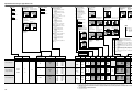
Detailed Diagram of Wiring Block Internal Connections
Flat cable connector 10, 20, 26 pins
● For -F100
● For -F101
Locations with protruding
part upward.
Connection to power
connecting terminal’s ( ) pole
Locations with protruding
part upward.
Unused pin
NC
OM
7 C M NC
O
5
C
8
3
Connection to power connecting
6
1
4
terminal’s (+) pole
NC
NC C 2
C
N
N
NC C NC
N
NC
Unused pin
NC
NC
7
5
8
3
6
1
4
NC
NC C 2
C
N
N
NC C NC
N
NC
Unused pin
Unused pin
Connection to power
connecting terminal’s (+) pole
To plug-in connector
Insert so that protruding
part is catched.
For the locations shown in the
above illustration, for the upper
part, insert the contact facing
upward , and for lower part, insert
the contact facing downward.
Note: As shown in the illustration
above, remove the connector
and then perform the wiring.
● For -F200
Locations with protruding
part upward.
15
13 6
1
11
9 2 14
7 0 1
1
5
8
3
6
1
4
2
● For -F201
Connection to power
connecting terminal’s
(+) pole
D sub connector
● For -F260
Locations with protruding
part upward.
Locations with protruding
part upward.
1
2 1
3 1 1
4 1 2
1
3
15
4
16
5
17
18 7 6
8
Connection to power
connecting terminal’s
( ) pole
To plug-in
connector
Insert so that protruding
part is catched.
For the locations shown in the
above illustration, for the upper
part, insert the contact facing
upward , and for lower part, insert
the contact facing downward.
To plug-in
connector
Connection to power
connecting terminal’s
( ) pole
Connection to power
connecting terminal’s
(+) pole
To plug-in
connector
C
9 N
7 1 NC
5 1 20
1
8
13 6 1 Unused
1
11
9 2 14
pin
7
0 1
5
1
8
3
6
1
4
2
● For -D250
● For -D251
9
7
5
6
11
13 0 8
15 2 1
NC 14 1
C
N 16
NC
3
4
1
2
Unused pin
Insert into the
added locations
Connection to power connecting
terminal’s ( ) pole
Connection to power connecting
terminal’s (+) pole
5
6
7 18 1
8
9 2 0 19
0
1
1
NC 22 2
23
2
3
4 15 14
6
71
1
Insert into the
added locations
Connection to power connecting
terminal’s (+) pole
Connection to power connecting
terminal’s ( ) pole
To plug-in connector
● For -T200
Locations with protruding
part upward.
OM
7C
5 1 NC
3 1 18
1
6
11 4 1
1
9
7 0 12
1
5
8
3
6
1
4
2
Note: As shown in the illustration above, remove the connector
and then perform the wiring.
524
Connection to power
connecting terminal’s
( ) pole
To plug-in
connector
Unused pin
Terminal block
Connection to power
connecting terminal’s
(+) pole
Manifold common wire
Unused pin
Insert so that protruding
part is catched.
For the locations shown in the
above illustration, for the upper
part, insert the contact facing
upward , and for lower part, insert
the contact facing downward.
To plug-in connector
To plug-in connector
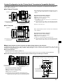
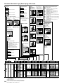
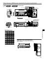
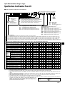
Product Configuration for the F Series Serial Transmission Compatible Manifold
In ordering the serial transmission compatible manifold, note that the product configurations vary between the F10 and F15
series, and the F18 series.
■ For
F10 and F15 series
A B A B A B
● The
manifold body and serial transmission block are connected by a flat cable, and mounted on one DIN rail at time of
delivery.
〔Figure 1〕
D
D
ADDRESS
1 2 4 8 16 32 64 128
G 24V 0V
POWER SEND
YS201L
YS2□L (For stand-alone, left-side mounting)※
YS2□R (For stand-alone, right-side mounting)※
YS391 (For Omron CompoBus/D)Note
MADE IN JAPAN
G 24V 0V
142160
Serial transmission block
(Stand-alone type)
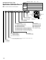
■ For
Serial Transmission Block, Single Unit
Manifold type solenoid valve
(Common for standard manifold of F201 type
wiring specification)
F18 series
A B
A B
※: About 100mm of a flat cable with connector is provided with the
serial transmission block.
Note: The transmission block uses Omron's remote I/O adapter-type DRT1OD16X, and therefore differs in shape from other transmission blocks.
Illustration shows the F10 series.
A B
〔Figure 2〕
● The
serial transmission block is fixed to the manifold at
time of delivery.
D
POWER SEND
D
ADDRESS
1 2 4 8 16 32 64 128
G 24V 0V
Serial Transmission Block, Single Unit
YS201S
MADE IN JAPAN
G 24V 0V
142160
YS2□S (For monoblock, left-side mounting)※
YS2□T (For monoblock, right-side mounting)※
YS391 (For Omron CompoBus/D)Note
※: Cables, etc., not provided with serial transmission block.
Note: The transmission block uses Omron's remote I/O adapter-type DRT1OD16X, and therefore differs in shape from other transmission blocks.
Serial transmission block
(Monoblock type)
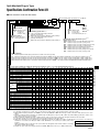
■Application Examples for Serial Transmission Block, Single Products (for reference)
If manifolds with flat cable connectors sold in the past have F201 wiring specifications (with plus common specifications only), the serial
transmission blocks (stand-alone type) YS2□L, YS391 or YS2□R in Figure 1 can be connected to the manifold to convert it into a serial
transmission-compatible manifold.
●Connectable Manifolds
• FM-SOLID MANIFOLD X80M and X88M Series
• Solenoid valves F series (F10 and F15 series are the same, with the exception of the above-described manifold and DIN rail.)
●Connection example between serial transmission block (stand-alone type) and earlier type of manifold
D
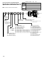
Mounting dimensions for serial transmission block, single product (Scale 1/3, Unit mm)
75
(12.5)
4
25
4
20.5
P
Serial Transmission Block, Single Unit
YS2□L ( For stand-alone, left-side mounting)※
YS2□R (For stand-alone, right-side mounting)※
YS391 (For Omron CompoBus/D)Note
90
82
(For mounting DIN rail)
10
Manifold type solenoid valve
(F201 wiring specification for plus common
specifications only)
5.5
YS201L
MADE IN JAPAN
G 24V 0V
φ4.4
R
35
D
ADDRESS
1 2 4 8 16 32 64 128
G 24V 0V
POWER SEND
142160
Serial transmission block
(Stand-alone type)
When ordering YS2□L or YS2□R as single unit, a DIN rail is included.
PR
Serial transmission block
10
※: Flat cable with connector provided with serial transmission block.
Note: The transmission block uses Omron's remote I/O adapter-type DRT1OD16X, and therefore differs in shape from other transmission blocks.
16 φ4.4
(For direct mounting)
7
50
525
SOLENOID VALVES F SERIES
Manifold type solenoid valve
(Manifold for serial transmission only)
Specifications of Serial Transmission Compatible Manifold
General Specifications
Voltage
Note: Internal wiring for the F10 and F15 series on the manifold side is the
same as the wiring specification -F201 of the split-type manifold plug-in
type. (flat cable connector type)
DC24V ±10%
Operating temperature range
5∼50˚C
Vibration resistance
49.0m/s2 {5.0G} (Conforms to JIS C 0911)
Shock resistance
98.1m/s2 {10.0G} (Conforms to JIS C0912)
● For details about specifications, see the user's manual. (See below)
Serial Transmission Block, Terminal Block (LED) Names
●For UNI-WIRE ® System
●For Mitsubishi Electric MELSECNET/MINI-S3
●For Omron SYSBUS Wire System
Transmission block specification: -01 (16-point output), -02 (8-point output)
Transmission block specification: -11
Transmission block specification: -21
×10
7 8
5 6
24V
0V
4
5
6
D
7
8
G
SD
24V
0V
RDA
RD
4
G
3
9
0 1 E
2 3
2 3
D
2
3
OFF
RDB
1
2
3
4
5
6
0 1 E
7 8
9
5 6
3
ON
1
T/ R
RUN ERR
ADDRESS
×1
PWR RUN ERR
POWER SEND
Dip switch for various settings
OFF
ON
ON
SDA
O
N
Rotary switch for station number setting
4
Address setting swtich
SDB
TERM
SG
FG
24V
+
0V
E. C. MODE switch
LED names
LED names
Display
Description
POWER
•Flashes during normal transmission.
•Lights up or shut off during faulty transmission.
SEND
Remark
Description
PWR
•Lights up when power is turned on.
RUN
•Lights up for normal data communication with master station.
SD
•Flashes during sending data.
RD
•Flashes during receiving data.
ERR
•Lights up when data receiving error occurs.
Shut off for normal communication.
®
※UNI-WIRE System is a serial parallel transmission
system developed jointly by NKE and Kuroda Precision
Industries. For details about UNI-WIRE System, see the
NKE or Kuroda Precision Industries catalog, user's
manual, etc.
● Number
of output points per block
16 solenoids (transmission block specification: -01)
8 solenoids (transmission block specification: -02)
● Related
materials: User's manual, document No.HV005
Remark
● Master
station: MELSEC-A series
AJ71PT32-S3,
AJ71T32-S3,
A2CCPU/A2CJCPU,
A1SJ71PT32-S3, link sub-stations up to a maximum of 64
stations, and link I/O points up to a maximum of 512 points.
※For details, see Mitsubishi Electric's sequencer
MELSEC-A series catalog, user's manual, etc.
● Number of output points per block
Maximum of 16 solenoids
※Since the block is equivalent to two stations, if the
block is entirely composed of sub-stations, the
maximum becomes 32 units.
● Related
FG
24V
0V
End station setting switch
LED names
Display
•Lights up when power is turned on.
•Flashes during voltage drops or over
current (a short circuit).
−
Display
Description
• Lights up when transmission is normal, and the PC
RUN
is in operations mode or monitor mode.
•Flashes during normal transmission.
•Lights up during standby or faulty transmission.
•Shut off during faults (during watchdog timer fault).
T/R
ERR
Remark
● Parent
station unit: SYSMAC-C (CV) series
C200H-RM201, C500-RM201
※ For details, see Omron's programmable controller
SYSMAC C(CV) series catalog, user's manual, etc.
● Number
of output points per block
Maximum of 16 solenoids
● Related
materials: User's manual, document No.HV007
materials: User's manual, document No.HV006
●For Omron B7A Link Terminal
●For Koyo Electronics Industries SA Bus
●For Sunx S-LINK
Transmission block specification: -31 (standard type), -32 (high-speed type)
Transmission block specification: -41 (16-point output), -42 (8-point output)
Transmission block specification: -51 (16-point output), -52 (8-point output)
Station number setting switch
Output selecting switch in faulty operation
1 2 3 4 5 6 7 8
PWR ERR
LOAD
OFF
ON
PWR ERR
POWER SEND
1
ERR
SIG
0V
LED names
Display
L+
L-
SHLD
L24V
LED names
Description
Display
•Lights up when power is turned on.
PWR
•Lights up when power is turned on.
ERR
•Lights up during faulty transmission.
ERR
•Lights up during faulty transmission or other faults.
Remark
● Connection
method: 1 to 1
(Transmission block specification) Standard type (-31)
High speed type (-32)
Max.31ms
Max.5ms
Transmission delay time
Transmission distance
Max.500m
Max.100m
※For details about the B7A Link Terminal, see the
Omron catalog, user's manual, etc.
● Number
of output points per block
Maximum of 16 solenoids
● Error
output specifications
Output mode: NPN open collector
Rated load voltage: DC24V
Output current: Sink current MAX. 40mA
materials: User's manual, document No.HV008
G
D
0V
2
3
24V
4
5
6
G
7
8
D
0V
24V
LED names
Description
PWR
526
ON
HOLD
24V
● Related
Switch for address setting and manipulating
output setting during error occurrence
Display
Description
POWER
•Lights up when power is turned on.
SEND
•Flashes during normal transmission.
•Lights up or shut off during faulty transmission.
Remark
※ For details about the SA Bus system, see the Koyo
Electronics Industries catalog, user's manual, etc.
● Number
of output points per block
16 solenoids (transmission block specification: -41)
8 solenoids (transmission block specification: -42)
● Related
materials: User's manual, document No.HV009
Remark
※For details about the S-LINK System, see the Sunx
catalog, user's manual, etc.
● Number
of output points per block
16 solenoids (transmission block specification: -51)
8 solenoids (transmission block specification: -52)
● Related
materials: User's manual, document No.HV010
●For Mitsubishi Electric MELSEC I/O LINK
●For Fuji Electric T Link Mini
●For Keyence KZ-R
Transmission block specification: -61
Transmission block specification: -71
Transmission block specification: -81
24V
0V
S1
POWER/ERROR
3
SD
FG
24V
0V
S+
7 8 9A
LED names
Display
PW
Description
•Lights up when power is turned on.
•Lights up when data transmitted from
master unit is normal.
RUN
RUN
Display
Description
PWR
•Lights up when power is turned on.
ALM
•Lights up during faulty transmission.
•Lights up during sending data to master unit.
RD
•Lights up during receiving data from master unit.
※ For details about the T Link Mini, see the Fuji
Electric catalog, user's manual, etc.
ERR.
•Lights up when faulty data transmitted from master unit.
● Number
Display
0V
Description
•Green : Lights up for normal
communications status.
•Orange : Lights up when communications status is poor.
(Can also light up when
address settings are
different)
•Red
: Lights up during faulty
operation, or when
transmission is cut off.
POWER/
ERROR
of output points per block
Maximum of 16 solenoids
materials: User's manual, document No.HV012
● 16
remote I/O unit connection stations, for a maximum
of 128 control input/output points
※For details, see Mitsubishi Electric's sequencer catalog,
user's manual, etc.
Remark
※For details about KZ-R, see the Keyence catalog,
user's manual, etc.
● Number
of output points per block
Maximum of 16 solenoids
● Number
of output points per block
Maximum of 16 solenoids
※Since the block is equivalent to four stations, if the
block is entirely composed of sub-stations, a maximum
of four units can connect to one master unit.
● Related
materials: User's manual, document No.HV013
materials: User's manual, document No.HV011
● For Omron CompoBus /D
● For Omron CompoBus/S
●For Mitsubishi Electric CC-Link
Transmission block specification: -91
Transmission block specification: -A1 (16-point output), -A2 (8-point output)
Transmission block specification: -B1
B RATE
8
●
8
●
8
6
1
2
3
4
5
6
●
●
RD
+24V (FG)
SLD
DG
DB
DA
Red
PWR
Shut off
•No setting status
Lights up
COMM
Shut off
•Serious breakdown
•Minor breakdown
Shut off
•No power supply
Lights up
ERR
LED names
State Display color
Lights up
•Normal status
Shut off
Green
Yellow
Red
Description
•During power supply.
•When power is not supplied.
•Communication fault, or standby.
•Communication fault occurred.
Remark
Lights up
•Serious communication fault.
※ For details about CompoBus/S, see the Omron catalog,
user's manual, etc.
Red
•Minor communication fault.
Shut off
•No power supply.
※ For details about CompoBus/D, see the Omron
catalog, user's manual, etc.
The transmission block is Omron's remote
adaptor-type DRT1-OD16X. For details about
handling, see Omron's user's manual.
● Number of output points per block
Maximum of 16 solenoids
● Number
of output points per block
16 solenoids (transmission block specification: -A1)
8 solenoids (transmission block specification: -A2)
● Related
•Lights up when power is turned on.
L RUN
materials: User's manual, document No.HV015
•Lights up when normal data is received
from master station.
SD
•Lights up for data sending.
RD
•Lights up for data receiving.
L ERR.
•Communication connection achieved.
Flashing
Description
PW
•During normal communication, or standby.
•No communication connection.
Green
Display
•During normal communication.
Flashing
Remark
●
4
NS
6
Green
Description
Flashing
Lights up
●
Lights up
●
HOLD/CLEAR switch
LED names
Display
State Display color
Flashing
MS
24G
FG
4
LED names
Lights up
BS−
0
ON
Transmission Internal circuit
power supply terminal
connector
Display
BDL
●
●
10
●
●
BS+ BDH
1
0
2
SD
●
2
NS
CLEAR
●
●
MS
HOLD
0
6
O
N
×10
●
2
Dip switch
STATION NO.
×1
PW L RUN L ERR.
●
PWR COMM ERR
Transmission speed setting switch Station number setting switch
4
Dip switch for various settings
•Lights up for transmission error, and shut off
for time over.
Lights up for station number setting error
or transmission speed setting error.
Remark
※For details about CC-Link, see the Mitsubishi Electric
catalog, user's manual, etc.
● Number
of output points per block
16 solenoids
※Since the block occupies one station, if the block is
entirely composed of remote I/O stations, a maximum of
64 units can connect to one master station.
● Related
materials: User's manual, document No.HV016
Related materials: User's manual, document No.HV014
■ For details about specifications and handling, see the above-listed user's manuals (document No. HV005∼HV016).
527
SOLENOID VALVES F SERIES
● Related
24V
Error holding swtich
Remark
● Related
FG
LED names
SD
Remark
0 1 E
S−
ON/OFF switch for end terminal resistance
LED names
9
ERROR MODE
HOLD
CLEAR
OFF
S2
ADDRESS
0 1 E
7 8
7 8
5 6
FG
4
DG
9
2 3
ON
RD
3
7 8
0 1 E
2 3
BCDE
9
2 3
DATA
3
3456
SD
PWR ALM
E
2
F01
5 6
3
4
ST. NO.
RUN ERR.
Address setting switch
5 6
PW
Station number setting switch
ADDRESS
×10
×1
4
Station number setting switch
Precautions for Use Due to Partial Specification Change (Deliveries from January 30, 1997)
■Description of Changes
Offering more durability and improved reliability, the coil dimensions have been changed.
Therefore, to identify between the earlier and new types due to a partial change in manifold dimensions,
parts of the outward color have been changed.
1.Changes in Single Valve Unit (Common to F10, F15, and F18 Series)
q S Type Plug Connector
Change 1 The coil is 5mm longer, and the valve total length becomes also 5mm longer.
Change 2 The connector location has been moved 2.5mm to the center.
Change 3 To identify between new and earlier types, the color of the manual override on the coil side has been changed from pink to light blue.
Unit mm
Earlier
New
※Illustration shows the F10 series.
Change 2
2.5
The connector location
has been moved 2.5 mm
to the center.
Change 1
The valve
total length is
5mm longer. Note
F10:105
F15:125.5
F18:138.5
Manual override:Pink
The coil is
5mm longer.
F10:110
F15:130.5
F18:143.5
Manual override:Light blue
Change 3
The color of the manual
override on the coil side
has been changed
from pink to light blue.
Note: The valve length is longer toward the coil side when mounting on the manifold.
w L Type Plug Connector
Change 1 The coil is 5mm longer, the valve total length becomes also 5mm longer.
Change 2 The connector section now becomes 3mm longer.
Change 3 To identify between new and earlier types, the color of the manual override on the coil side has been changed from pink to light blue.
Unit mm
Earlier
New
※Illustration shows the F10 series.
43.5
Change 2
3
40.5
Change 1
The valve
total length is
5mm longer.Note
F10:94
F15:114.5
F18:127.5
Manual override:Pink
The connector section
now becomes
3mm longer.
The coil is
5mm longer.
F10:99
F15:119.5
F18:132.5
Manual override:Light blue
Change 3
The color of the manual
override on the coil side
has been changed
from pink to light blue.
Note: The valve length is longer toward the coil side when mounting on the manifold.
2.Change in Connector Receptacle Shape of Plug-in Type Manifold (Common to F10, F15, and F18 Series)
■Target Products: Split Manifold Plug-in Type, and Serial Transmission Compatible Manifold
Change 1 Connector receptacle position for valve assembly became 3mm deeper due to the change in the valve's L type plug connector.
Change 2 To identify between new and earlier types, the color of the valve assembly cover has been changed from ivory to light blue.
New
Earlier
※Illustration shows the F10
series.
Change 1
The plug-in connector
location is 3mm deeper.
Change 2
The color of the valve assemble
cover has been changed.
Cover
Color: Ivory
528
Cover
Color: light blue
■Precautions for Valve Replacement
1.About Combined Mountings of New and Earlier Types of Valves, and Manifolds
●For split-type manifolds plug-in type, and the serial transmission compatible manifolds, a change in the connector
receptacle brings up some issues when combining earlier and new types of mounting valves and combination of the
valves and manifolds on replacing the valves. For details about earlier and new combinations, see the table below.
● Since split manifolds non-plug-in type, and monoblock manifolds and PC board manifolds, do not have plug-in
construction, consequently all combinations of earlier and new types are acceptable.
※Illustration shows the F10 series.
Valve
Earlier
Manifold
Color of manual override
on coil side: Pink
New
Mounting screw
Caution
Sub-plate is
required
(Service parts)
Earlier
Color of cover
on the valve
base assembly:
Ivory
Earlier
type
Earlier type
Cover
Color: Ivory
Cover
Color: Ivory
Caution: The sub-plate shown in the illustration above is
required to align the heights in the connector
section. Always attach a sub-plate to mount the
valve. Note that the valve height is 3mm higher than
the earlier type, and that the valve length on the coil
side is 5mm longer.
●●
Targeted products
New type
Manual override
color: Light blue
Mounting screw
(3mm longer screw
provided with sub-plate)
Mounting screw
Mounting screw
New type
Earlier type
Manual override
Color: Pink
SOLENOID VALVES F SERIES
Serial transmission compatible manifold
Split manifold plug-in type
Earlier type
Manual override
Color: Pink
Color of manual override on
coil side: Light blue
Manual override
Color: Light blue
Caution
New
Color of cover
on the valve
base assembly:
light blue
New type
New type
Cover
Color: Light blue
Cover
Color: Light blue
The change in connector
receptacle prevents the
connector section from
connecting firmly,
resulting in poor contact.
Caution: Sub-plate not required.
Use of a sub-plate prevents the connector
section from connecting firmly, resulting in poor
contact.
2.Sub-plate (Service Parts)
The sub-plate is provided as a service part, necessary to mount the new type valves on the earlier type split manifold
plug-in type and on the earlier type serial transmission compatible manifold.
Sub-plate (Sub-plate, gasket, O ring, 2 mounting screws)
F
Z-S
Valve size
10 : 10mm width
15 : 15mm width
18 : 18mm width
529
530
F Series Order Code
The solenoid valves F series order codes are
classified into the following 8 categories.
For details on order codes, see the
designated pages.
F
T :Single valve unit
Koganei solenoid
valves F series
p. 532
M□A:Monoblock manifold A type (base piping type)
● 10 :10mm width
(Effective area 5mm2)
● 15 :15mm width
(Effective area10mm2)
● 18 :18mm width
(Effective area18mm2)
p. 534
M□F:Monoblock manifold F type (direct piping type)
p. 536
M□AP:PC board manifold A type (base piping type)
p. 538
M□FP:PC board manifold F type (direct piping type)
p. 540
M□N:Split manifold non-plug-in type
p. 542
M□P:Split manifold plug-in type
p. 546
M□S:Serial transmission compatible manifold
p. 550
531
SOLENOID VALVES F SERIES
Valve size
Single Valve Unit Order Code
■Valve size
10mm width
■Operation method
■Valve specification
2-position
single solenoid
specification
(for single solenoid only)
4
(A)
Internal pilot type
Effective area 10mm2
External pilot typeNote
(for positive pressure)
T0
4
(A)
5
(R1)
2
(B)
1
(P)
External pilot typeNote
(for vacuum)※
※: This is a vacuum valve.
Note: When using as a
single unit, select
-A2 (A type with
sub-base) for the
valve output type.
Without a subbase, piping for
the external pilot
cannot be
available.
3
( R 2)
18mm width
Effective area 18mm2
T1
2-position
double solenoid specification
(for both single and double
solenoid types)
4
(A)
5
(R1)
2
(B)
1
(P)
A type with plate
T2
Manual override
4
(A)
5
(R1)
2
(B)
1
(P)
A type with subbase
-A2
-FJ5
Output port fitting
F10:φ4
F15:φ6
F18:φ8
With output port
single size fitting
block
Blank
-FJ6
Manual lever override
(made to order) Note1
3-position
(ABR connection)
4
(A)
5
(R1)
2
(B)
1
(P)
-R
3
( R 2)
Output port fitting
F10:φ4 ,φ6
F15:φ6 ,φ8
F18:φ8 ,φ10
With output port
female thread block
With input port
female thread block
-F4
Output port
F10:M5×0.8
F15:Rc1/8
F18:Rc1/4
With output port
single size fitting block
With input port
female thread block
Output port fitting
F10:φ6
F15:φ8
F18:φ10
Output port fitting
F10:φ4
F15:φ6
F18:φ8
With output port
female thread block
With output port
single size fitting block
With input port
female thread block
-FM
4
(A)
5
(R1)
2
(B)
1
(P)
F10:M5×0.8
F15:Rc1/8
F18:Rc1/4
3
( R 2)
-F6
Output port fitting
F10:φ6
F15:φ8
F18:φ10
T5
F10
F15
F18
Operation method
Manual override
Valve output type
Wiring specification
Blank Note2
T1
-A1 Note2
-FM Note2
-PN
Blank
-A2
-F3 Note3
-PS
-R Note1
-FJ Note2
-F4 Note3
-PL
Blank
G
T3
T4 Note4
T5
Note4
S type plug connector
Lead wire 300mm
-PS
L type plug connector
Lead wire 300mm
-PL
S type plug connector
Lead wire 3000mm
L type plug connector
Lead wire 3000mm
-PL3
T0
T2
S type plug connector
Without connector
-PS3
3-position
(PAB connection)
Valve specification
Blank
-F5
T4
Valve size
L type plug connector
Without connector
-PN
3
( R 2)
T3
-F3
-A1
Output port
F10:Rc1/8
F15:Rc1/8
F18:Rc1/4
3-position
(all port block)
Output port fitting
F10:φ4 ,φ6
F15:φ6 ,φ8
F18:φ8 ,φ10
With output port
single size fitting
block
■Manual override
3
( R 2)
F18
-FJ
Blank
V
2-position
single solenoid specification
(for both single and double
solenoid types)
F15
■Wiring
specification
G
1
(P)
3
( R 2)
15mm width
With output port
different size fitting
block
With output port different
size fitting block
With input port
female thread block
5
(R1)
2
(B)
F10
Without input/
output block
Blank
Effective area 5mm2
■Valve output type
V
Blank
-FJ5 Note2
-F5 Note3
-PS3
Note2
-F6 Note3
-PL3
-FJ6
Voltage
DC24V
DC12V
AC100V
Notes: 1. The manual lever override is made to order. Contact us for the delivery. When the valve specifications are T1 or T2, the manual lever override is available
for the A side only.
2. Two manifold mounting screws are included.
3. The units with input port female thread block can be used only when the operation method is the internal pilot type valve.
4. Not available for the vacuum valve.
532
Additional Parts Order Code for Single Valve Unit
● For internal pilot
F
Z -
Valve size
10:10mm width
15:15mm width
18:18mm width
Parts content
21 : Mounting bracket (mounting bracket, 2 mounting screws)
25 : Sub-base (sub-base body, gasket, exhaust valve) Note 1
P
: Plate (plate, gasket, 2 mounting screws)
J
: Different size fitting block (fitting block, gasket, 2 mounting screws)
J5 : Single size fitting block F10: φ4, F15: φ6, F18: φ8 (fitting block, gasket, 2 mounting screws)
J6 : Single size fitting block F10: φ6, F15: φ8, F18: φ10 (fitting block, gasket, 2 mounting screws)
M
: Female thread block (female thread block, gasket, 2 mounting screws)
MP : P port female thread block (P port female thread block, gasket) Note 1
GS1 : Gasket (gasket, exhaust valve) Note 2
Notes: 1. Valve mounting screws are not included.
2. Be aware that this gasket is different from the GS2 gasket for the split-type manifolds.
Sub-base for external pilot
●For external pilot
F
Z -
Valve size
10:10mm width
15:15mm width
18:18mm width
F
Parts content
P
: Plate (plate, gasket, 2 mounting screws)
J
: Different size fitting block (fitting block, gasket, 2 mounting screws)
J5 : Single size fitting block F10: φ4, F15: φ6, F18: φ8 (fitting block, gasket, 2 mounting screws)
J6 : Single size fitting block F10: φ6, F15: φ8, F18: φ10 (fitting block, gasket, 2 mounting screws)
M
: Female thread block (female thread block, gasket, 2 mounting screws)
GS1 : Gasket (gasket, exhaust valve) Note 2
ZG - 25
Valve size
10:10mm width
15:15mm width
18:18mm width
Notes: Be aware that this gasket is different from the GS2 gasket for the split type manifolds.
Connector-related order code
Valve
specification
For T1, T2,
T3, T4, T5
FZ0 Connector specification
CP
: Connector, lead wire length 300mm (black, red, white,
for total of 3 lead wires)
CP3 : Connector, lead wire length 3000mm (black, red, white,
for total of 3 lead wires)
CLN : Connector without lead wire (1 short bar and 3 contacts
included)
CC1.5 : Cabtire cable, length 1500mm ※
CC3 : Cabtire cable, length 3000mm ※
Valve
specification
For T0
Connector specification
CP : Connector, lead wire length 300mm (black, red, for
total of 2 lead wires)
CP3 : Connector, lead wire length 3000mm (black, red,
for total of 2 lead wires)
CLN : Connector without lead wire (1 short bar, 2 contacts
included)
※For details, see p. 513.
Exhaust valve
25:Sub-base
GS1:Gasket
MP:P port female thread block
P:Plate
M:Female thread block
J, J5, J6:Fitting block
21:Mounting bracket
533
SOLENOID VALVES F SERIES
FZ -
Monoblock Manifold A Type (Base Piping) Order Code
■Valve size
■Operation method
F10M
Blank
Internal pilot typeNote4
10mm width Effective area 5mm2
F15M
G
15mm width Effective area 10mm2
External pilot typeNote5
(for positive pressure)
F18M
18mm width Effective area 18mm2
V
■Manifold output specification
With single size fitting
block
(base piping type)
With different size
fitting block
(base piping type)
External pilot typeNote5
(for vacuum)※
※: This is a vacuum valve.
Note: Cannot be combined
with a positive
pressure valve.
■Individual air supply and exhaust spacer
Plus common prewiring connection
Blank : Without spacer
L type plug connector S type plug connector
-NPM : Individual air supply spacer (with M5
Lead wire 300mm
Without connector
female thread for F10)
-NP6 : Individual air supply spacer (with φ6
fitting for F15)
-NP8 : Individual air supply spacer (with φ8
fitting for F15 and F18)
-NP0 : Individual air supply spacer (with φ10
fitting for F18)
Blank
-CPS
-NRM : Individual exhaust spacer (with M5 female
thread for F10)
S type plug connector Plus common pre-NR6 : Individual exhaust spacer (with φ6 fitting
wiring connection
Without connector
for F15)
L type plug connector
-NR8 : Individual exhaust spacer (with φ8 fitting
Lead wire 300mm
for F15 and F18)
-NR0 : Individual exhaust spacer (with φ10
fitting for F18)
For details, see p.516.
■Wiring
specification
-PN
J
■Manual override
L
Output port fitting
F10:φ4 ,φ6
F15:φ6 ,φ8
F18:φ8 ,φ10
Output port fitting
F10:φ4 or φ6
F15:φ6 or φ8
F18:φ8 or φ10
S type plug connector
Lead wire 300mm
Manual override
With female thread
block (base piping type)
-CPL
Plus common prewiring connection
S type plug connector
Lead wire 3000mm
■Manifold fitting
specification
Manifold side
output port single
fitting
-PS
Blank
L type plug connector
Lead wire 300mm
Manual lever override
(made to order) Note2
M
Output port female
thread
F10:M5×0.8
F15:Rc1/8
F18:Rc1/4
-CPS3
Plus common prewiring connection
L type plug connector
Lead wire 3000mm
-J5
Output port fitting
F10:φ4
F15:φ6
F18:φ8
Manifold side
output port single
fitting
-PL
S type plug connector
Lead wire 3000mm
-R
■Valve specification
-CPL3
T0 : 2-position, for single solenoid only
T1 : 2-position, single solenoid
specification
T2 : 2-position, double solenoid
specification
T3 : 3-position, all port block
T4 : 3-position, ABR connection
T5 : 3-position, PAB connection
-J6
■ Valve output type
Output port fitting
F10:φ6
F15:φ8
F18:φ10
-PS3
With plate Note 3
(base piping type)
L type plug connector
Lead wire 3000mm
■Pilot specification
-A1
Blank
Internal pilot manifold
-PL3
G
External pilot manifold
Note: Valves of different sizes can not be
combined together for mounting.
Valve
size
Valve
units
Manifold output
specification
Pilot
specification
Station
Valve
size
Valve
specification
Operation Manual
method override
Manifold model
M
F15M
F18M
2
・
・
・
20
Wiring
specification
Manifold fitting
specification
Individual air supply
and exhaust spacer
Voltage
Mounting valve models
J
F10M
Valve output type
Blank
G
stn. 1
・
・
・
stn.□
F10
F15
T0
T3
T1
T4Note6 G Note5
T2
T5Note6 V Note5
F18
Blank
Note4
Blank
Blank
-R Note2
Note1
-A1
Note3
-PN
-PS
-PL
-PS3
-PL3
Blank
-CPS
-CPL
-CPS3
-CPL3
-NPM
-NP6
-NP8
-NP0
-NRM
-NR6
-NR8
-NR0
DC24V
DC12V
AC100V
BP (for block-off plate)
A
Blank
Note4
L
Blank
G
stn. 1
・
・
・
stn.□
Note1
F10
F15
T0
T3
T1
T4Note6 G Note5
T2
T5Note6 V Note5
Blank
Blank
-R Note2
-A1
Note3
F18
-PN
-PS
-PL
-PS3
-PL3
-CPS
-CPL
-CPS3
-CPL3
Blank
-J5
-J6
-NPM
-NP6
-NP8
-NP0
-NRM
-NR6
-NR8
-NR0
DC24V
DC12V
AC100V
BP (for block-off plate)
Notes: 1. Valve mounting location from the left, with the solenoid on top, and A and B ports front.
2. The manual lever override is made to order. Contact us for the delivery. When the valve specifications are T1 or T2, the manual lever override is placed
on the A side only.
3. Always enter -A1.
4. Cannot be mounted on the external pilot manifold.
534 5. Cannot be mounted on the internal pilot manifold.
6. Not available for the vacuum valve.
Additional Parts Order Code for Monoblock Manifold A Type
Gasket (gasket and exhaust valve)
F
Z - GS1
Valve size
10:10mm width
15:15mm width
18:18mm width
GS1:Gasket
BP:Block-off plate
Block-off plate (block-off plate and 2 mounting screws)
F
BP
Valve size
10:10mm width
15:15mm width
18:18mm width
Connector-related order code
FZ
-
Connector specification
CP
: Connector, lead wire length 300mm
Blank : For T1, T2, CP3 : Connector, lead wire length 3000mm
CLN : Connector without lead wire (short bar
T3, T4, T5
and contacts included)
0 : For T0
PA
: Plus common A type, lead wire length 300mm ※
PA3 : Plus common A type, lead wire length 3000mm ※
※For details, see
PB
: Plus common B type, lead wire length 300mm ※
p.513.
PB3 : Plus common B type, lead wire length 3000mm ※
PC
: Plus common C type, lead wire length 300mm ※
PC3 : Plus common C type, lead wire length 3000mm ※
CC1.5 : Cabtire cable, length 1500mm Note ※
CC3 : Cabtire cable, length 3000mm Note ※
Note: Not available for T0.
Valve
specification
Red Common wire (+)
Black A side (–)
White B side (–) (Insert when using as double solenoid)
C type:FZ-PC□※
Red Common wire (+)
Black A side (–)
White B side (–) (Insert when using as double solenoid)
Red
Black
White
Red
Common wire (+)
A side (–)
B side (–) (Insert when using as double solenoid)
Common wire (+) ※: Lead wire length Blank: 300mm
3: 3000mm
Note: White lead wire is not
available for FZ0-P□ □.
F
Z -
Note
Valve size
10:10mm width
15:15mm width
Note 18:18mm width
Note
Specification
NPM :
NP6 :
NP8 :
NP0 :
NRM :
NR6 :
NR8 :
NR0 :
Individual air supply spacer (with M5 female thread for F10)
Individual air supply spacer (with φ6 fitting for F15)
Individual air supply spacer (with φ8 fitting for F15 and F18)
Individual air supply spacer (with φ10 fitting for F18)
Individual exhaust spacer (with M5 female thread for F10)
Individual exhaust spacer (with φ6 fitting for F15)
Individual exhaust spacer (with φ8 fitting for F15 and F18)
Individual exhaust spacer (with φ10 fitting for F18)
※For details, see p.516.
Muffler
KM - J
Manifold Order Code Example
(6 units of F10 Series)
F10M6AL
stn.1∼ 2 F10T0-A1-PS-J5 DC24V
stn.3∼ 5 F10T2-A1-PS-J6 DC24V
stn.6
F10BP-J6
Note: This order code example has no relation to the illustration at upper right.
Fitting size
6 : Outer diameter φ 6 (for individual exhaust
spacer)
8 : Outer diameter φ 8 (for individual exhaust
spacer)
10 : Outer diameter φ 10 (for individual exhaust
spacer)
(Sales unit: Set of 10 mufflers)
Precautions for Order Code
●Manifold output specification
Select either “with fitting block” or “with female thread block.” For repair or replacement, purchase the single valve unit additional parts, F□ Z-J (different size
fitting block), F□ Z-J□ (single size fitting block), or F□ Z-M (female thread block), on p. 533.
● Orders for valves only
Place orders from “Single Valve Unit Order Code” on p. 532. Note, however, that the only compatible valve type is A1. In addition, for common terminal wiring
connections, order separately the common connector assemblies listed above.
535
SOLENOID VALVES F SERIES
for non-plug-in type, gasket,
( Spacer
exhaust valve and 2 mounting screws )
:FZ-PA□※
B type :FZ-PB□※
For external pilot
Individual air supply
and exhaust spacer
●Common connector assembly
A type
Exhaust valve
Monoblock Manifold F Type (Direct Piping) Order Code
■Valve size
■Valve output type
F10M
With different size
fitting block
(direct piping type)
10mm width
■Wiring
specification
L type plug connector
Without connector
Plus common prewiring connection
S type plug connector
Lead wire 300mm
Effective area 5mm2
F15M
15mm width
-FJ
Effective area 10mm2
Output port fitting
F10:φ4 ,φ6
F15:φ6 ,φ8
F18:φ8 ,φ10
F18M
18mm width
Effective area 18mm2
-CPS
Blank
S type plug connector
Without connector
Plus common prewiring connection
L type plug connector
Lead wire 300mm
With output port
single size fitting block
(direct piping type)
■Valve specification
-PN
T0 : 2-position, for single solenoid only
T1 : 2-position, single solenoid
specification
-FJ5
T2 : 2-position, double solenoid
specification
Output port fitting
T3 : 3-position, all port block
F10:φ4
T4 : 3-position, ABR connection
F15:φ6
T5 : 3-position, PAB connection
F18:φ8
With output port
single size fitting block
(direct piping type)
■Manual override
S type plug connector
Lead wire 300mm
-CPL
Plus common prewiring connection
S type plug connector
Lead wire 3000mm
-PS
L type plug connector
Lead wire 300mm
-CPS3
Plus common prewiring connection
L type plug connector
Lead wire 3000mm
Manual override
-FJ6
-PL
Output port fitting
F10:φ6
F15:φ8
F18:φ10
Blank
S type plug connector
Lead wire 3000mm
-CPL3
With female thread
block
(direct piping type)
Manual lever override
(made to order) Note2
-PS3
-R
L type plug connector
Lead wire 3000mm
-FM
Output port female
thread
F10:M5×0.8
F15:Rc1/8
F18:Rc1/4
■Individual air supply and exhaust spacer
Blank : Without spacer
-NPM : Individual air supply spacer (with M5
female thread for F10)
-NP6 : Individual air supply spacer (with φ6
fitting for F15)
-NP8 : Individual air supply spacer (with φ8
fitting for F15 and F18)
-NP0 : Individual air supply spacer (with φ10
fitting for F18)
-NRM : Individual exhaust spacer (with M5 female
thread for F10)
-NR6 : Individual exhaust spacer (with φ6 fitting
for F15)
-NR8 : Individual exhaust spacer (with φ8 fitting
for F15 and F18)
-NR0 : Individual exhaust spacer (with φ10 fitting
for F18)
For details, see p.516.
-PL3
Note: Valves of different sizes can not be
combined together for mounting.
Valve
size
Valve
units
Station
Valve
size
Valve specification
Manifold model
Manual
override
Valve output
type
Wiring specification
F15M
F18M
2
・
・
・
20
Voltage
Mounting valve models
Blank
F10M
Individual air supply
and exhaust spacer
F
stn. 1
・
・
・
stn.□
Note1
F10
F15
F18
T0
T3
T1
T4
T2
T5
-FJ
Blank
-FJ5
-R Note 2
-FJ6
-FM
-PN
-PS
-PL
-PS3
-PL3
Blank
-CPS
-CPL
-CPS3
-CPL3
-NPM
-NRM
DC24V
-NP6
-NR6
DC12V
-NP8
-NR8
AC100V
-NP0
-NR0
BP (for block-off plate)
Notes 1: Valve mounting location from the left, with solenoid on top, and A and B ports front.
2: The manual lever override is made to order. Contact us for the delivery. When the valve specifications are T1 or T2, the manual lever override is placed on
the A side only.
Remark: The external pilot valve cannot be mounted on the F type manifold.
536
Additional Parts Order Code for Monoblock Manifold F Type
Gasket (gasket and exhaust valve)
F
Z - GS1
Valve size
10:10mm width
15:15mm width
18:18mm width
GS1:Gasket
BP:Block-off plate
Block-off plate (block-off plate and 2 mounting screws)
F
BP
Valve size
10:10mm width
15:15mm width
18:18mm width
Connector-related order code
-
Valve
specification
Blank: For T1,
T2, T3,
T4, T5
0: For T0
※For details, see
p.513.
Connector specification
CP
: Connector, lead wire length 300mm
CP3 : Connector, lead wire length 3000mm
CLN : Connector without lead wire (short bar,
contacts included)
PA
: Plus common A type, lead wire length 300mm ※
PA3 : Plus common A type, lead wire length 3000mm ※
PB
: Plus common B type, lead wire length 300mm ※
PB3 : Plus common B type, lead wire length 3000mm ※
PC
: Plus common C type, lead wire length 300mm ※
PC3 : Plus common C type, lead wire length 3000mm ※
CC1.5 : Cabtire cable, length 1500mm Note ※
CC3 : Cabtire cable, length 3000mm Note ※
Note: Not available for T0.
Exhaust valve
Individual air supply
and exhaust spacer
for non-plug-in type, gasket,
( Spacer
exhaust valve and 2 mounting screws )
●Common connector assembly
A type:FZ-PA□※
Red Common wire (+)
Black A side (–)
White B side (–) (Insert when using as double solenoid)
B type:FZ-PB□※
C type:FZ-PC□※
Red Common wire (+)
Black A side (–)
White B side (–) (Insert when using as double solenoid)
Red
Black
White
Red
Common wire (+)
A side (–)
B side (–) (Insert when using as double solenoid)
Common wire (+) ※: Lead wire length Blank: 300mm
3: 3000mm
Note: White lead wire is not
available for FZ0-P□ □.
F
Z -
Note
Note
Note
Valve size
10:10mm width
15:15mm width
18:18mm width
Specification
NPM :
NP6 :
NP8 :
NP0 :
NRM :
NR6 :
NR8 :
NR0 :
Individual air supply spacer (with M5 female thread for F10)
Individual air supply spacer (with φ6 fitting for F15)
Individual air supply spacer (with φ8 fitting for F15 and F18)
Individual air supply spacer (with φ10 fitting for F18)
Individual exhaust spacer (with M5 female thread for F10)
Individual exhaust spacer (with φ6 fitting for F15)
Individual exhaust spacer (with φ8 fitting for F15 and F18)
Individual exhaust spacer (with φ10 fitting for F18)
※For details, see p. 516.
Muffler
KM - J
Manifold Order Code Example
(4 units of F10 Series)
F10M4F
stn.1 ∼ 2 F10T0-FJ5-PS DC24V
stn.3
F10T2-FJ6-PS DC24V
stn.4
F10BP
Note: This order code example has no relation to the illustration at upper right.
Fitting size
6 : Outer diameter φ6 (for individual exhaust
spacer)
8 : Outer diameter φ8 (for individual exhaust
spacer)
10 : Outer diameter φ10 (for individual exhaust
spacer)
(Sales unit: Set of 10 mufflers)
Precautions for Order Code
● Orders for valves only
Place orders from “Single Valve Unit Order Code” on p. 532.
Select from valve types -FJ, -FJ5, -FJ6, or -FM. In addition, for common terminal wiring connections, order separately the common connector assemblies listed
above.
537
SOLENOID VALVES F SERIES
FZ
PC Board Manifold A Type (Base Piping) Order Code
■ Manifold output
specification
With different size fitting
block (base piping type)
■Pilot specification
■Wiring connection specification
Blank
■Individual air supply and exhaust spacer
Blank : Without spacer
-NPM : Individual air supply spacer (with M5 female thread for F10)
-NP6 : Individual air supply spacer (with φ6 fitting for F15)
-NP8 : Individual air supply spacer (with φ8 fitting for F15 )
-NRM : Individual exhaust spacer (with M5 female thread for F10)
-NR6 : Individual exhaust spacer (with φ6 fitting for F15)
-NR8 : Individual exhaust spacer (with φ8 fitting for F15)
For details, see p.516.
-S
Internal pilot manifold
Single wiring: Wiring as single solenoid only.
Note: This is not the same as packed wiring.
G
-W
External pilot manifold
Double wiring: Wiring is always for the double
solenoid, regardless of the specifications of the mounted valve.
J
Output port fitting
F10:φ4 ,φ6
F15:φ6 ,φ8
■ Wiring specification
(wiring block)
With female thread
block (base piping type)
■Operation method
Flat cable connector
(with socket and strain relief)
■Manual override
■Valve output type
■Manifold fitting
specification
Note 9
Blank
With plate
(base piping type)
Manual override
Internal pilot type Note6
Manifold side
output port single size fitting
G
M
External pilot type Note7
(for positive pressure)
-F20□
Output port female
thread
F10:M5×0.8
F15:Rc1/8
-J5
Output port fitting
F10:φ4
F15:φ6
Manual lever override
(made to order) Note8
External pilot type Note7
(for vacuum)※
※: This is a vacuum valve.
With single size fitting
block (base piping type)
-A1
Blank
V
-F200:20-pin
-F201:20-pin
For details, see p.558.
■Wiring specification
S type plug connector
Lead wire for PC
board Note9
Note: Cannot be combined with a valve for
positive pressure.
Manifold side
output port single size fitting
-R
L
-J6
-PP
Output port fitting
F10:φ4 or φ6
F15:φ6 or φ8
Output port fitting
F10:φ6
F15:φ8
■Valve specification
T0 : 2-position, for single solenoid only
T1 : 2-position, single solenoid
specification
T2 : 2-position, double solenoid
specification
T3 : 3-position, all port block
T4 : 3-position, ABR connection Note 10
T5 : 3-position, PAB connection Note 10
■Valve size
F10M
10mm width, Effective area 5mm2
F15M
Note: Valves of different sizes can not
be combined together for
mounting.
15mm width, Effective area 10mm2
Valve
size
Valve
units
Manifold output
specification
Pilot
Wiring
specification specification
Wiring connection
specification
Station
Valve
size
Operation Manual
method override
Valve
specification
Double wiring type Note 2
Single wiring type Note 1
Manifold model
6
8
10
12
14
16
Wiring
Manifold fitting
type
specification
specification
Individual air supply
and exhaust spacer
Voltage
Mounting valve models
J
Blank
-F200
M
G
-F201
-S
stn. 1
・
・
・
stn.□
F10
F15
Blank
T0
T1
G Note7
V Note7
Note5
Note4
Blank
Note6
Blank
-R
Note8
-A1
-PP
Note9
Note9
-NPM -NRM DC24V
-NP6 -NR6 DC12V
-NP8 -NR8
BPC (for block-off plate)
AP
L
Note3
Blank
-F200
G
-F201
-S
stn. 1
・
・
・
stn.□
F10
F15
Note4
F10M
F15M
J
M
6
8
Valve output
Blank
G
-F200
-F201
-W
stn. 1
・
・
・
stn.□
BlankNote6
T0
T1
G Note7
V Note7
Note5
Blank
-R Note8
Blank
-A1
-PP
Note9
Note9
-J5
-J6
-NPM -NRM DC24V
-NP6 -NR6 DC12V
-NP8 -NR8
BPC (for block-off plate)
F10
F15
Note4
T0 T3
T1 T4 Note10
T2 T5 Note10
BlankNote6
G Note7
V
Note7
Blank
-R
Note8
-A1
Note9
Blank
-NPM -NRM DC24V
-NP6 -NR6 DC12V
-NP8 -NR8
-PP
Note9
Note11
BPC (for block-off plate)
AP
Note3
L
Blank
-F200
G
-F201
-W
stn. 1
・
・
・
stn.□
Note4
F10
F15
T0 T3
T1 T4 Note10
T2 T5 Note10
BlankNote6
G Note7
V Note7
Blank
-R Note8
-A1
Note9
-PP
Note9
Note11
Blank
-J5
-J6
-NPM -NRM DC24V
-NP6 -NR6 DC12V
-NP8 -NR8
BPC (for block-off plate)
Notes: 1. Wiring as single solenoid only. Note that this is not the same as packed wiring. The mounting valves are limited to single solenoid only (T0, T1 specifications). Therefore, even if the T1 specification
valve is switched over to a double solenoid, no current will be applied to the B side solenoid.
2. Wiring is always for the double solenoid, regardless of the specifications of the mounted valve.
3. Number of units in terms of the wiring connection specifications are, for single wiring, 6 ~16 (even numbers only), and for double wiring, 6 or 8.
4. Valve mounting location from the left, with solenoid on top, and A and B ports front.
5. The mounting valves are limited to T0, T1 specifications only (single solenoid specifications). In addition, even if the T1 specification valve is switched over to a double solenoid, no current will be
applied to the B side solenoid.
6. Cannot be mounted on the external pilot manifold.
7. Cannot be mounted on the internal pilot manifold.
8. The manual lever override is made to order. Contact us for the delivery. When the valve specifications are T1 or T2, the manual lever override is placed on the A side only.
9. Always enter -A1 or -PP.
10. Not available for the vacuum valve.
11. Lead wire on solenoid B side (white) is not available for the valve specification T0.
538
Additional Parts Order Code for PC Board Manifold A Type
Gasket (gasket and exhaust valve)
F
Z - GS1
GS1:Gasket
Valve size
10:10mm width
15:15mm width
BPC:Block-off plate
Block-off plate
(block-off plate, 2 mounting screws and housing)
F
BPC
Valve size
10:10mm width
15:15mm width
Connector-related order code
FZ
-
Valve
specification
Blank: For T1,
T2, T3,
T4, T5
0: For T0
Connector specification
P10 : For F10 series
Connector lead wire for PC board manifold
P15 : For F15 series
Connector lead wire for PC board manifold
Exhaust valve
For external pilot
Red Common wire (+)
Housing※
Black Side A (–)
White Side B (–)
※: Use as a cover when the block-off plate is attached.
Note
Note: White lead wire is not
available for FZ0-P□.
Individual air supply
and exhaust spacer
for non-plug-in type, gasket,
( Spacer
exhaust valve and 2 mounting screws )
F
Valve size
10:10mm width
15:15mm width
Z Specification
NPM
NP6
NP8
NRM
NR6
NR8
:
:
:
:
:
:
Individual air supply spacer (with M5 female thread for F10)
Individual air supply spacer (with φ6 fitting for F15)
Individual air supply spacer (with φ8 fitting for F15)
Individual exhaust spacer (with M5 female thread for F10)
Individual exhaust spacer (with φ6 fitting for F15)
Individual exhaust spacer (with φ8 fitting for F15)
※For details, see p.516.
Manifold Order Code Example
(8 units of F10 Series)
Muffler
KM - J
F10M8APL-F201-W
stn.1 ∼ 4 F10T0-A1-PP-J5 DC24V
stn.5 ∼ 7 F10T2-A1-PP-J6 DC24V
stn.8
F10BPC-J6
Note: This order code example has no relation to the illustration at upper right.
Fitting size
6 : Outer diameter φ 6 (for individual exhaust spacer)
8 : Outer diameter φ 8 (for individual exhaust spacer)
10 : Outer diameter φ 10 (for individual exhaust spacer)
(Sales unit: Set of 10 mufflers)
Precautions for Order Code
● Orders for valves only
Use the code
Valve size
Valve specification
Pilot specification
Manual override - Valve output type - PP Voltage to order.
If the lead wire for PC board is not necessary, enter -PN.
● Wiring connection specification
-S (single wiring): Wiring as single solenoid only.
-W (double wiring): Wiring is always for the double solenoid, regardless of the specifications of the mounted valve.
539
SOLENOID VALVES F SERIES
(Insert when using as a double solenoid)
PC Board Manifold F Type (Direct Piping) Order Code
■Valve size
■Manual override
■Valve output type
Manual override
With different size
fitting block
(direct piping type)
F10M
10mm width
■Wiring specification
With output port
single size fitting block
(direct piping type)
S type plug connector
Lead wire for PC board
Effective area 5mm2
F15M
15mm width
-FJ
Blank
Effective area 10mm2
Manual lever override
(made to order) Note6
■ Wiring specification
(wiring block)
Flat cable connector
(with socket and strain relief)
Output port fitting
F10:φ4 ,φ6
F15:φ6 ,φ8
With female thread
block
(direct piping type)
-FJ5
-PP
Output port fittings
F10:φ4
F15:φ6
With output port
single size fitting block
(direct piping type)
■Individual air supply and exhaust spacer
Blank : Without spacer
-NPM : Individual air supply spacer (with M5
female thread for F10)
-NP6 : Individual air supply spacer (with φ6
fitting for F15)
-NP8 : Individual air supply spacer (with φ8
fitting for F15)
-NRM : Individual exhaust spacer (with M5 female
thread for F10)
-NR6 : Individual exhaust spacer (with φ6 fitting
for F15)
-NR8 : Individual exhaust spacer (with φ8 fitting
for F15)
For details, see p.516.
-R
-FM
Output port female
thread
F10:M5×0.8
F15:Rc1/8
-F20□
-FJ6
Output port fitting
F10:φ6
F15:φ8
-F200:20-pin
-F201:20-pin
For details, see
p. 558.
■Wiring connection specification
■Valve specification
T0
T1
T2
T3
T4
T5
-S
Single wiring: Wiring as single
solenoid only.
Note: This is not the same as packed
wiring.
:
:
:
:
:
:
2-position, for single solenoid only
2-position, single solenoid specification
2-position, double solenoid specification
3-position, all port block
3-position, ABR connection
3-position, PAB connection
-W
Double wiring: Wiring is always for
the double solenoid,
regardless of the
mounted valve type.
Note: Valves of different sizes can not be
combined together for mounting.
Valve
size
Valve
units
Wiring
specification
Wiring connection
specification
Station
Valve
size
Valve
specification
Double wiring type Note 2
Single wiring type Note 1
Manifold model
6
8
10
12
14
16
F10M
FP
Manual
override
Valve output
type
-F200
-F201
-S
stn. 1
・
・
・
stn.□
T0
T1
F10
Blank
-R
Note5
F15
Note6
-FJ
-FJ5
-FJ6
-FM
Blank
-PP
Note7
-NPM -NRM
-NP6 -NR6
-NP8 -NR8
DC24V
DC12V
Note4
BPC (for block-off plate)
F15M
Note3
Voltage
Mounting valve models
Note3
6
8
Individual air supply and
Wiring
exhaust spacer
specification
FP
-F200
-F201
-W
stn. 1
・
・
・
stn.□
F10
F15
T0
T1
T2
T3
T4
T5
Blank
-R
Note6
-FJ
-FJ5
-FJ6
-FM
Blank
-PP
Note7
Note8
-NPM -NRM
-NP6 -NR6
-NP8 -NR8
DC24V
DC12V
Note4
BPC (for block-off plate)
Notes:1. Wiring as single solenoid only. Note that this is not the same as packed wiring. The mounting valves are limited to single solenoid only (T0, T1
specifications). Therefore, even if the T1 specification valve is switched over to a double solenoid, no current will be applied to the B side solenoid.
2. Wiring is always for the double solenoid, regardless of the specifications of the mounted valve.
3. Number of units in terms of the wiring connection specifications are, for single wiring 6∼16 (even numbers only), and for double wiring, 6 or 8.
4. Valve mounting location from the left, with solenoid on top, and A and B ports front.
5. The mounting valves are limited to T0, T1 specifications only (single solenoid specifications). In addition, even if the T1 specification valve is switched
over to a double solenoid, no current will be applied to the B side solenoid.
6. The manual lever override is made to order. Contact us for the delivery. When the valve specifications are T1 or T2, the manual lever override is placed
on the A side only.
7. Always enter -PP.
8. Lead wire on solenoid B side (white) is not available for the valve specification T0.
540
Additional Parts Order Code for PC Board Manifold F Type
Gasket (gasket and exhaust valve)
F
Z - GS1
GS1:Gasket
Valve size
10:10mm width
15:15mm width
BPC:Block-off plate
Block-off plate
(block-off plate, 2 mounting screws and housing)
F
BPC
Valve size
10:10mm width
15:15mm width
Connector-related order code
FZ
-
Valve
specification
Blank: For T1,
T2, T3,
T4, T5
0: For T0
Connector specification
P10 : For F10 series
Connector lead wire for PC board manifold
P15 : For F15 series
Connector lead wire for PC board manifold
Exhaust valve
Red Common wire (+)
Housing※
Black Side A (–)
White Side B (–)
※: Use as a cover when the block-off plate is attached.
Note: White lead wire is not
available for FZ0-P□.
Individual air supply
and exhaust spacer
F
for non-plug-in type, gasket,
( Spacer
exhaust valve and 2 mounting screws )
Z -
Valve size
10:10mm width
15:15mm width
Specification
NPM
NP6
NP8
NRM
NR6
NR8
:
:
:
:
:
:
Individual air supply spacer (with M5 female thread for F10)
Individual air supply spacer (with φ6 fitting for F15)
Individual air supply spacer (with φ8 fitting for F15)
Individual exhaust spacer (with M5 female thread for F10)
Individual exhaust spacer (with φ6 fitting for F15)
Individual exhaust spacer (with φ8 fitting for F15)
※For details, see p.516.
Manifold Order Code Example
(8 units of F10 Series)
Muffler
KM - J
F10M8FP-F201-W
stn.1∼ 4 F10T0-FJ5-PP DC24V
stn.5∼ 7 F10T2-FJ6-PP DC24V
stn.8
F10BPC
Note: This order code example has no relation to the illustration at upper right.
Fitting size
6 : Outer diameter φ6 (for individual exhaust spacer)
8 : Outer diameter φ8 (for individual exhaust spacer)
10 : Outer diameter φ10 (for individual exhaust spacer)
(Sales unit: Set of 10 mufflers)
Precautions for Order Code
● Orders for valves only
Use the code Valve size
Valve specification
Manual override - Valve output type - PP Voltage to order.
If the lead wire for PC board is not necessary, enter -PN.
● Wiring connection specification
-S (single wiring): Wiring as single solenoid only.
-W (double wiring): Wiring is always for the double solenoid, regardless of the specifications of the mounted valve.
541
SOLENOID VALVES F SERIES
(Insert when using as a double solenoid) Note
Split Manifold Non-Plug-in Type Order Code
■Manifold output specification
With different size
fitting block
(base piping type)
F10M
10mm width
■Pilot specification
With single size fitting
block (base piping type)
■Piping block specification
Different size fitting block
-JR : Different size fitting, right-side
mounting
-JL : Different size fitting, left-side
mounting
-JD : Different size fitting, both-sides
mounting
Fitting size (P and R ports)
F10, F15 : φ8, φ10 F18 : φ12 only
Blank
Internal pilot manifold
Effective area 5mm2
G
F15M
External pilot manifold
15mm width
J
Effective area 10mm2
F18M
18mm width
Effective area 18mm2
Output port fitting
F10:φ4 ,φ6
F15:φ6 ,φ8
F18:φ8 ,φ10
With female thread
block
(base piping type)
L
Output port fitting
F10:φ4 orφ6
F15:φ6 orφ8
F18:φ8 orφ10
Female thread block
-MR : Female thread, right-side
mounting
-ML : Female thread, left-side
mounting
-MD : Female thread, both-side
mounting
Female thread size (P and R ports)
F10, F15 : Rc1/4 F18 : Rc3/8
With plate
(direct piping type)
M
■Valve specification
Single size fitting block (F18 cannot be
selected)
-J5R : Single size fitting, right-side
mounting
-J5L : Single size fitting, left-side
mounting
-J5D : Single size fitting, both-side
mounting
Fitting size (P and R ports) F10 and
F15 : φ8
-J6R : Single size fitting, right-side
mounting
-J6L : Single size fitting, left-side
mounting
-J6D : Single size fitting, both-side
mounting
Fitting size (P and R ports) F10 and
F15 : φ10
Blank
Output port female
thread
F10:M5×0.8
F15:Rc1/8
F18:Rc1/4
T0 : 2-position, for single
solenoid only
T1 : 2-position, single
solenoid specification
T2 : 2-position, double
solenoid specification
T3 : 3-position, all port block
T4 : 3-position, ABR
connection
T5 : 3-position, PAB
connection
■Valve output type
■Wiring specification
With plate Note3
(base piping type)
S type plug connector
Without connector
-A1
With different size
fitting block
(direct piping type)
■Manifold fitting specification
Manifold side
output port single
size fitting
-PN
With output port single
size fitting block
(direct piping type)
Manifold side
output port single
size fitting
-J5
S type plug connector S type plug connector
Lead wire 300mm
Lead wire 3000mm
■Operation method
-J6
Output port fitting
F10:φ4
F15:φ6
F18:φ8
Output port fitting
F10:φ6
F15:φ8
F18:φ10
Blank
Internal pilot type Note5
-FJ
G
External pilot type Note6
(for positive pressure)
※ No vacuum valve can be
mounted.
■ Manual override
Manual override
Output port fitting
F10:φ4 ,φ6
F15:φ6 ,φ8
F18:φ8 ,φ10
With female thread
block
(base piping type)
-FJ5
-PS
Output port fitting
F10:φ4
F15:φ6
F18:φ8
With output port single
size fitting block
(direct piping type)
Plus common prewiring connection
S type plug connector
Lead wire 300mm
-PS3
Plus common prewiring connection
S type plug connector
Lead wire 3000mm
-CPS
-FM
Blank
Manual lever override
(made to order) Note2
Output port female
thread
F10:M5×0.8
F15:Rc1/8
F18:Rc1/4
■Split
Blank :
-SP :
-SR :
-SA :
Without split
For P port Note 4
For R port Note 4
For both P and R
ports Note 4
-CPS3
-FJ6
Output port fitting
F10:φ6
F15:φ8
F18:φ10
■Individual air supply and exhaust spacer
Blank : Without spacer
-NPM : Individual air supply spacer (with M5 female
thread for F10)
-NP6 : Individual air supply spacer (with φ6 fitting for F15)
-NP8 : Individual air supply spacer (with φ8 fitting for
F15 and F18)
-NP0 : Individual air supply spacer (with φ10 fitting for F18)
-NRM : Individual exhaust spacer (with M5 female thread
for F10)
-NR6 : Individual exhaust spacer (with φ6 fitting for F15)
-NR8 : Individual exhaust spacer (with φ8 fitting for F15 and
F18)
-NR0 : Individual exhaust spacer (with φ10 fitting for F18)
For details, see p.516.
-R
Note: Valves of different sizes can
not be combined together for
mounting.
Valve size
Manifold output
specification
Valve units
Pilot specification
Piping block specification
Station
Valve
size
Valve
specification
Operation
method
Manual
override
Manifold model
Base piping type
F10M
Base piping type
single size fitting
F15M
F18M
Direct piping type
2
・
・
・
20
J
Blank
M
G
L
G
Blank
Blank
Manifold fitting
Wiring
specifications specification
Individual air supply
and exhaust spacer
Split
Voltage
Blank
DC24V
DC12V
AC100V
Mounting valve models
Blank
N
Valve
output type
G
Note7
-JR
-JL
-JD
-MR
-ML
-MD
-J5R
-J6R Note7
-J5L Note7
-J6L Note7
-J5D Note7
-J6D Note7
stn. 1
・
・
・
stn.□
-JR
-JL
-JD
-MR
-ML
-MD
-J5R Note7
-J6R Note7
-J5L Note7
-J6L Note7
-J5D Note7
-J6D Note7
stn. 1
・
・
・
stn.□
-JR
-JL
-JD
-MR
-ML
-MD
-J5R Note7
-J6R Note7
-J5L Note7
-J6L Note7
-J5D Note7
-J6D Note7
stn. 1
・
・
・
stn.□
Note1
F10
F15
T0
T1
T2
T3
T4
T5
Blank Note5
G Note6
Blank
-R Note2
-A1
Note3
F18
-PN
-PS
-PS3
-CPS
-CPS3
Blank
-NPM
-NP6
-NP8
-NP0
-NRM
-NR6
-NR8
-NR0
Note1
F15
T0
T1
T2
T3
T4
T5
Blank Note5
G Note6
Blank
-R Note2
-A1
Note3
F18
-PN
-PS
-PS3
-CPS
-CPS3
Blank
-J5
-J6
-NPM
-NP6
-NP8
-NP0
-NRM
-NR6
-NR8
-NR0
Note1
F15
T0
T1
T2
T3
T4
T5
Blank Note5
G Note6
Blank
-R Note2
F18
BPN (for block-off plate)
Blank
-SP Note4
-SR Note4
DC24V
DC12V
AC100V
-SA Note4
BPN (for block-off plate)
F10
-SR Note4
-SA Note4
BPN (for block-off plate)
F10
-SP Note4
-FJ
-FJ5
-FJ6
-FM
-PN
-PS
-PS3
-CPS
-CPS3
Blank
-NPM
-NP6
-NP8
-NP0
-NRM
-NR6
-NR8
-NR0
Blank
-SP Note4
-SR Note4
DC24V
DC12V
AC100V
-SA Note4
Notes: 1. Valve mounting location is from the left, with solenoid on top, and A and B ports front.
2. The manual lever override is made to order. Contact us for the delivery. When the valve specifications are T1 or T2, the manual lever override is placed on the A
side only.
3. When selecting J, M, or L (base piping type) for the manifold output specification, always enter -A1 (with plate) for the valve output type.
4. Splits can be installed only when piping blocks are mounted on both sides. In addition, only 1 piece split may be mounted in one manifold for -SA, or one each split for
-SP and -SR, for a total of two locations. When in delivery, the designated splits are mounted between the designated station and the station to its immediate left (the
next smaller stn. No.).
5. Cannot be mounted on the external pilot manifold.
6. Cannot be mounted on the internal pilot manifold.
7. F18 cannot be selected.
542
543
SOLENOID VALVES F SERIES
■Valve size
Additional Parts Order Code for Split Manifold Non-Plug-in Type
Manifold parts
F
Piping block assembly
Z -
F
Valve size
10:10mm width
15:15mm width
18:18mm width
Parts content
GS2 : Gasket (gasket and exhaust valve)
SP : Split (for P port)
SR : Split (for R port)
SA : Split (for both P and R ports)
Z
Piping specification
PJ: Different size fitting piping block
(For F18, single size fitting φ12)
PJ5: Single size fitting piping block φ8
(For F18 cannot be selected)
PJ6: Single size fitting piping block φ10
(For F18 cannot be selected)
PM: Female thread piping block
Valve size
10:10mm width
15:15mm width
18:18mm width
Block-off plate (block-off plate, 2 mounting screws and plug ※)
F
※: No plug is included in F18.
BP N
Valve size
10:10mm width
15:15mm width
18:18mm width
Pilot specification
Blank : Internal pilot
G : External pilot
For non-plug-in
End blocks (one set of left and right)
F
Connector-related order code
FZ
※For details, see
p.513.
Connector specification
CP
: Connector, lead wire length 300mm
CP3 : Connector, lead wire length 3000mm
CLN : Connector without lead wire (short bar, contacts
included)
PA
: Plus common A type, lead wire length 300mm※
PA3 : Plus common A type, lead wire length 3000mm※
PB
: Plus common B type, lead wire length 300mm※
PB3 : Plus common B type, lead wire length 3000mm※
PC
: Plus common C type, lead wire length 300mm※
PC3 : Plus common C type, lead wire length 3000mm※
CC1.5 : Cabtire cable, length 1500mm Note ※
CC3 : Cabtire cable, length 3000mm Note ※
Note: Not available for T0.
-E
Valve size
Pilot specification
10:10mm width Blank : Internal pilot※
15:15mm width
G : External pilot (only for F10 and F15)
18:18mm width ※: For F18, internal pilot and external pilot use are shareable.
-
Valve
specification
Blank: For T1,
T2, T3,
T4, T5
0: For T0
Z
Independent air supply
and exhaust spacer
for non-plug-in type, gasket,
( Spacer
exhaust valve and 2 mounting screws )
F
Z -
Valve size
10:10mm width
15:15mm width
18:18mm width
●Common connector assembly
Specification
NPM :
NP6 :
NP8 :
NP0 :
NRM :
NR6 :
NR8 :
NR0 :
Individual air supply spacer (with M5 female thread for F10)
Individual air supply spacer (with φ6 fitting for F15)
Individual air supply spacer (with φ8 fitting for F15 and F18)
Individual air supply spacer (with φ10 fitting for F18)
Individual exhaust spacer (with M5 female thread for F10)
Individual exhaust spacer (with φ6 fitting for F15)
Individual exhaust spacer (with φ8 fitting for F15 and F18)
Individual exhaust spacer (with φ10 fitting for F18)
※For details, see p.516.
A Type :FZ-PA□※
Red Common wire (+)
Black A side (–)
White B side (–) (Insert when using as double solenoid) Note
Muffler
B Type:FZ-PB□※
KM - J
Red Common wire (+)
Black A side (–)
Note
White B side (–) (Insert when using as double solenoid)
C Type:FZ-PC□※
Red
Black
White
Red
※: Lead wire length Blank: 300mm
3: 3000mm
Fitting size
6 : Outer diameter φ6 (for individual exhaust spacer)
8 : Outer diameter φ8 (for individual exhaust spacer)
10 : Outer diameter φ10 (for F10, F15 and for individual
exhaust spacer)
12 : Outer diameter φ12 (for F18)
(Sales unit: Set of 10 mufflers)
Common wire (+)
A side (–)
Note
B side (–) (Insert when using as double solenoid)
Common wire (+) Note: White lead wire is not
available for FZ0-P□□.
Connecting rod (F18 series only)
F18 Z -
Valve base assembly (valve base and gasket)
F
Z
Valve size
10:10mm width
15:15mm width
18:18mm width
Piping specification
VJ : Different size fitting valve base
VJ5 : Single size fitting valve base F10: φ4, F15: φ6, F18: φ8
VJ6 : Single size fitting valve base F10: φ6, F15: φ8, F18: φ10
VM : Female thread valve base
VP : Valve base plate
Pilot specification
Blank: Internal pilot※
G : External pilot (only for F10 and F15)
※ For F18, internal pilot and external pilot use are shareable.
544
Additional unit number
01~20 (01~04 for RH)
※For reduction of units, consult us.
Specification
RV: For valve base
RH: For piping and wiring base
GS2:Gasket
BPN:Block-off plate
Plug
Piping block assembly
SP:Split for the P port Note
SR:Split for the R port Note
End block
Exhaust valve
Valve base assembly
SOLENOID VALVES F SERIES
Note: The F18 series split looks different in its appearance.
※The illustration shows the F10 series.
Manifold Order Code Example
(4 units of F10 Series)
F10M4NL-J5R
stn.1∼ 2
stn.3
stn.4
F10T0-A1-PS-J5 DC24V
F10T2-A1-PS-J6 DC24V
F10BPN-J6
Note: This order code example has no relation to the illustration above.
Precautions for Order Code
●Orders for valves only
Place orders from “Single Valve Unit Order Code” on p. 532.
However, Blank, A2, F3, F4, F5, and F6 cannot be selected for the valve output type. And for the wiring specification, Blank, PL, and PL3 cannot be selected.
In addition, for common terminal wiring connections, separately order the common connector assemblies listed on the previous page.
545
Split Manifold Plug-in Type Order Code
■Manifold output specification
With different size
fitting block
(base piping type)
■Pilot specification
With single size fitting
block
(base piping type)
■Wiring specification (wiring block)
■Wiring connection specification
Flat cable connector
(with socket and strain relief)
Blank
Internal pilot manifold
■Valve specification
T0
T1
T2
T3
T4
T5
Blank
Packed wiring: Wiring is made
accordance with
the mounted valve
specifications.
G
External pilot manifold
J
L
Output port fitting
F10:φ4 or φ6
F15:φ6 or φ8
F18:φ8 orφ10
With female thread
block
(base piping type)
With plate
(direct piping type)
M
-F100:10-pin
-F101:10-pin
-F200:20-pin
-F201:20-pin
-F260:26-pin
For details, see p. 560.
Terminal block
(19 terminals M3 screws)
D sub connector
■Piping block specification
Different size fitting block
-JR : Different size fitting, right-side
mounting
-JL : Different size fitting, left-side
mounting
-JD : Different size fitting, both-side
mounting
Fitting size (P and R ports)
F10, F15 : φ8, φ10 F18 : φ12 only
Blank
F10M
10mm width
Effective area 5mm2
F15M
■Manifold fitting specification
With plate Note 4
(base piping type)
Manifold side
Manifold side
output port single
size fitting
output port single
size fitting
-A1
■Operation method
-J5
With different size
fitting block
(direct piping type)
Blank
With output port single
size fitting block
(direct piping type)
Internal pilot type Note8
-J6
Output port fitting
F10:φ4
F15:φ6
F18:φ8
Output port fitting
F10:φ6
F15:φ8
F18:φ10
G
■Wiring position
(wiring block)
External pilot type Note9
(for positive pressure)
※ No vacuum valve can be
mounted.
-FJ
■Manual override
-D25□
Single size fitting block (F18 cannot be
selected)
-J5R : Single size fitting, right-side mounting
-J5L : Single size fitting, left-side mounting
-J5D : Single size fitting, both-side mounting
Fitting size (P and R ports) F10 and
F15 : φ8
-J6R : Single size fitting, right-side mounting
-J6L : Single size fitting, left-side mounting
-J6D : Single size fitting, both-side mounting
Fitting size (P and R ports) F10 and
F15 : φ10
■Valve size
Double wiring: Wiring is always for
the double solenoid,
regardless of the
specifications of the
mounted valve.
Blank : Left-side mounting
-R : Right-side mounting
Female thread block
-MR : Female thread, right-side mounting
-ML : Female thread, left-side mounting
-MD : Female thread, both-side mounting
Female thread size (P and R ports)
F10, F15 : Rc1/4 F18 : Rc3/8
Output port female
thread
F10:M5×0.8
F15:Rc1/8
F18:Rc1/4
2-position, for single solenoid only
2-position, single solenoid specification
2-position, double solenoid specification
3-position, all port block
3-position, ABR connection
3-position, PAB connection
-W
-F□
Output port fitting
F10:φ4 ,φ6
F15:φ6 ,φ8
F18:φ8 ,φ10
:
:
:
:
:
:
■Valve output type
-T200
Manual override
(Fitting stand M2.6
Also can provide
screws)
the terminal block
-D250:25-pin
with cover.Note10
-D251:25-pin
For details, see p. 560.
■Individual air supply and exhaust spacer
-FJ5
Output port fitting
F10:φ4 ,φ6
F15:φ6 ,φ8
F18:φ8 ,φ10
Output port fitting
F10:φ4
F15:φ6
F18:φ8
With female thread
block
(direct piping type)
With output port single
size fitting block
(direct piping type)
Blank : Without spacer
-PPM : Individual air supply spacer (with M5 female thread
for F10)
-PP6 : Individual air supply spacer (with φ6 fitting for F15)
-PP8 : Individual air supply spacer (with φ8 fitting for F15
and F18)
-PP0 : Individual air supply spacer (with φ10 fitting for F18)
-PRM : Individual exhaust spacer (with M5 female thread for
F10)
-PR6 : Individual exhaust spacer (with φ6 fitting for F15)
-PR8 : Individual exhaust spacer (with φ8 fitting for F15
and F18)
-PR0 : Individual exhaust spacer (with φ10 fitting for F18)
For details, see p.516.
Blank
-FM
Manual lever override
(made to order) Note6
-FJ6
Output port female
thread
F10:M5×0.8
F15:Rc1/8
F18:Rc1/4
Output port fitting
F10:φ6
F15:φ8
F18:φ10
■Split
Blank
-SP
-SR
-SA
:
:
:
:
-R
Without split
For P port Note 7
For R port Note7
For both P and R
ports Note7
15mm width
F18M
18mm width
Effective area 18mm2
Note: Valves of different sizes can not be
combined together for mounting.
Valve
size
Valve
units
Manifold output
specification
Pilot
specification
Piping block
specification
Wiring specification
Wiring connection
specification
Wiring
position
Voltage
Station
Valve
size
Valve specification
Operation
method
Manifold model
Base
piping type
Base
piping type
single size
fitting
Direct
piping type
F10M
F15M
F18M
2
・
・
・
□
J
Blank
M
G
Blank
P
L
G
Note1
Blank
Blank
G
Note11
Valve output Manifold fitting
specification
type
Individual air supply
and exhaust spacer
Split
Voltage
Mounting valve models
-JR
-JL
-JD
-MR
-ML
-MD
-J5R
-J6R Note11
-J5L Note11
-J6L Note11
-J5D Note11
-J6D Note11
-F100 -D250
-F101 -D251
-F200 -T200
-F201
-F260
-JR
-JL
-JD
-MR
-ML
-MD
-J5R Note11
-J6R Note11
-J5L Note11
-J6L Note11
-J5D Note11
-J6D Note11
-F100 -D250
-F101 -D251
-F200 -T200
-F201
-F260
-JR
-JL
-JD
-MR
-ML
-MD
-J5R Note11
-J6R Note11
-J5L Note11
-J6L Note11
-J5D Note11
-J6D Note11
-F100 -D250
-F101 -D251
-F200 -T200
-F201
-F260
Blank
Blank
-W
-R
DC24V
DC12V
Note2
AC100V
stn. 1
・
・
・
stn.□
F10
F15
T0
T1
T2
Blank
Blank
-W
-R
DC24V
DC12V
Note2
AC100V
stn. 1
・
・
・
stn.□
Blank
Blank
-W
-R
stn. 1
・
・
・
stn.□
Note3
Notes: 3.
4.
5.
6.
7.
8.
9.
10.
11.
Blank
Blank Note8
G Note9
Blank
-R Note6
-A1
-PPM
-PP6
-PP8
-PP0
Note4
-PRM
-PR6
-PR8
-PR0
F10
F15
T0
T1
T2
T3
T4
T5
Blank
Blank Note8
G Note9
Blank
-R Note6
-A1
Note4
F10
F15
T0
T1
T2
T3
T4
T5
Blank Note8
G Note9
-J5
-J6
F18
BPP (for block-off plate)
-PPM
-PP6
-PP8
-PP0
-PRM
-PR6
-PR8
-PR0
-R Note6
F18
BPP (for block-off plate) Note5
-SP Note7
-SR Note7
DC24V
DC12V
Note2
AC100V
Blank
-SP Note7
-SR Note7
DC24V
DC12V
Note2
AC100V
-SA Note7
Note5
Blank
Blank
-SA Note7
BPP (for block-off plate) Note5
Note3
DC24V
DC12V
Note2
AC100V
T3
T4
T5
F18
Note3
Notes: 1. For the maximum number of units, see the table for the maximum number of valve units, by wiring specification, on p. 548.
2. AC100V is available only for the wiring specifications -D250, -D251 (D sub connector) and -T200 (terminal block).
546
Manual
override
-FJ
-FJ5
-FJ6
-FM
Blank
-PPM
-PP6
-PP8
-PP0
-PRM
-PR6
-PR8
-PR0
Blank
-SP Note7
-SR Note7
DC24V
DC12V
Note2
AC100V
-SA Note7
Valve mounting location is from the left, with the solenoid on top, and A and B port side in front.
When selecting J, M, or L (base piping type) for the manifold output specification, always enter -A1 (with plate) for the valve output type.
Be aware that the block-off plate wiring is always double wiring (allocated 2 control pins at 1 stn.) regardless of the wiring connection specification.
The manual lever override is made to order. Contact us for the delivery. When the valve specifications are T1 or T2, the manual lever override is placed on the A side only.
Splits can be installed only when piping blocks are mounted on both sides. In addition, only 1 piece split may be mounted in one manifold for -SA, or one each split for -SP and -SR, for a total of two
locations. When in delivery, the designated splits are mounted between the designated station and the station to its immediate left (the next smaller stn. No.).
Cannot be mounted on the external pilot manifold.
Cannot be mounted on the internal pilot manifold.
The terminal block with cover (code: append -139W to the end of the manifold code) can also be provided as a made to order item. For details, contact us.
F18 cannot be selected.
547
SOLENOID VALVES F SERIES
Effective area 10mm2
Additional Parts Order Code for Split Manifold Plug-in Type
Manifold parts
F
Wiring block assembly (one set)
Z -
F
Valve size
10:10mm width
15:15mm width
18:18mm width
Parts content
GS2 : Gasket (gasket and exhaust valve)
SP : Split (for P port)
SR : Split (for R port)
SA : Split (for both P and R ports)
※ For F18, internal pilot
and external pilot use
are shareable.
For plug-in
Valve base assembly (valve base, gasket, lead wire and plug-in connector)
F
Z
-
Valve size
10:10mm width
15:15mm width
18:18mm width
F
Z -
Valve size
10:10mm width
15:15mm width
18:18mm width
Piping specification
VJ : Different size fitting valve base
VJ5 : Single size fitting valve base F10:φ4, F15: φ6, F18: φ8
VJ6 : Single size fitting valve base F10: φ6, F15,φ8, F18: φ10
VM : Female thread valve base
VP : Valve base plate
Specification
PPM
PP6
PP8
PP0
PRM
PR6
PR8
PR0
※For details, see p. 516.
Fitting size
6 :Outer diameter φ6 (for individual exhaust spacer)
8 :Outer diameter φ8 (for individual exhaust spacer)
10 :Outer diameter φ10 (for F10, F15 and for individual
exhaust spacer)
12 :Outer diameter φ12 (for F18)
(Sales unit: Set of 10 mufflers)
Piping specification
PJ : Different size fitting piping blocks (for F10 and
F15)
PJ5 : Single size fitting piping block φ8 (Not
available for F18)
PJ6 : Single size fitting piping blockφ10 (Not
available for F18)
PM : Female thread piping block (for F10, F15)
PJP : Fitting piping block (for F18 only)
PMP : Female thread piping block (for F18 only)
Connecting rod (F18 series only)
F18 Z -
Additional unit number
01~20 (01~04 for RH)
※Example: To add two valve units, enter -02.
※For reduction of units, consult us.
Pilot specification
Blank : Internal pilot
G : External pilot
End blocks (one set of left and right)
Z
Specification
RV: For valve base
RH: For piping and wiring base
-
End block specification
Valve size
E :For F10, F15
10:10mm width
EP:For F18
15:15mm width
18:18mm width Pilot specification
Blank : Internal pilot※
G : External pilot (only for F10 and F15)
※: For F18, internal pilot and external pilot use are shareable.
548
Individual air supply spacer (with M5 female thread for F10)
Individual air supply spacer (with φ6 fitting for F15)
Individual air supply spacer (with φ8 fitting for F15 and F18)
Individual air supply spacer (withφ10 fitting for F18)
Individual exhaust spacer (with M5 female thread for F10)
Individual exhaust spacer (with φ6 fitting for F15)
Individual exhaust spacer (with φ8 fitting for F15 and F18)
Individual exhaust spacer (with φ10 fitting for F18)
KM - J
-
Valve size
10:10mm width
15:15mm width
18:18mm width
F
:
:
:
:
:
:
:
:
Muffler
Piping block assembly
Z
for plug-in type, gasket,
( Spacer
exhaust valve and 2 mounting screws )
-
※: For F18, internal pilot
and external pilot use
are shareable.
F
Piping specification
F100 :Flat cable connector (DC specification)
F101 :Flat cable connector (DC specification)
F200 :Flat cable connector (DC specification)
F201 :Flat cable connector (DC specification)
F260 :Flat cable connector (DC specification)
D250 :D sub connector
D251 :D sub connector
T200L :Terminal block for left-side mounting
T200R :Terminal block for right-side mounting
Individual air supply
and exhaust spacer
Wiring specification
D: For D sub connector
F: For flat cable connector, terminal block
Pilot
specification
Blank : Internal pilot※
G : External pilot
(only for F10 and F15)
Voltage (Not required for T200)
DC24
DC12
AC100(for D250,D251only)
Pilot specification
Blank : Internal pilot※
G : External pilot
(Only for F10 and F15)
BP P
Valve size
10:10mm width
15:15mm width
18:18mm width
-
Valve size
10:10mm width
15:15mm width
18:18mm width
Block-off plate (block-off plate, 2 mounting screws and plug)
F
Z
■Table for maximum number of valve units, by wiring specification
Maximum number of units
Wiring connection specification
Wiring specification
Max. control pts.
F100 Flat cable (10P)
8 points
F101 Flat cable (10P)
8 points
F200 Flat cable (20P)
16 points
F201 Flat cable (20P)
16 points
F260 Flat cable (26P)
20 points
D250 D sub connector (25P)
16 points
D251 D sub connector (25P)
20 points
T200 Terminal block (19 terminals)
18 points
Packed wiring (Blank)
Varies depending on the
mounted number of single
solenoids, double
solenoids, and block-off
plates. The number of
controlled solenoids should
be designated at the
maximum number of control
points or less.
Double wiring (-W)
4 units
4 units
8 units
8 units
10 units
8 units
10 units
9 units
GS2:Gasket
Plug
BPP:Block-off plate
SP:Split for the P port
SR:Split for the R port
End block
Piping block assembly
Plug-in connector
Valve base assembly
Wiring block
assembly
Note: The F18 series split looks different in its appearance.
※The illustration shows the F10 series.
SOLENOID VALVES F SERIES
Exhaust valve
Manifold Order Code Example
(12 units of F10 Series)
F10M12PL-J5R-F201 DC24V
stn.1∼ 8 F10T0-A1-J5 DC24V
stn.9∼ 11 F10T2-A1-J6 DC24V
stn.12
F10BPP-J6
Note: This order code example has no relationship to the illustration above.
Precautions for Order Code
●Orders for valves only
Place orders from “Single Valve Unit Order Code” on p. 532.
However, Blank, A2, F3, F4, F5, and F6 cannot be selected for the valve output type. For the wiring specification, Blank is the only selection.
●Wiring connection specification
Blank (packed wiring) : Wiring is made accordance with the mounted valve specifications.
-W (double wiring) : Wiring is always for the double solenoid, regardless of the mounted valve specifications.
549
■Manifold output specification
With different size
fitting block
(base piping type)
■Pilot specification
With single size
fitting block
(base piping type)
※For the order code for Omron CompoBus/D, see p. 554.
■Transmission block specification
■Wiring connection specification
※ These are the serial transmission block
specifications compatible with each
system.
Blank
Internal pilot manifold
Blank
Packed wiring: Wiring is made
accordance with
the mounted valve
specifications.
F10, F15 series
For details, see
p. 525 ∼ 527.
G
External pilot manifold
J
T0
T1
T2
T3
T4
T5
:
:
:
:
:
:
■Valve output type
2-position, for single solenoid only
2-position, single solenoid specification
2-position, double solenoid specification
3-position, all port block
3-position, ABR connection
3-position, PAB connection
Output port fitting
F10:φ4 ,φ6
F15:φ6 ,φ8
F18:φ8 ,φ10
Output port fitting
F10:φ4 or φ6
F15:φ6 or φ8
F18:φ8 or φ10
With female thread
block
(base piping type)
With plate
(direct piping type)
●Delivered with mounted on the
DIN rail.
■Piping block specification
Different size fitting block
-JR : Different size fitting, right-side
mounting
-JL : Different size fitting, left-side
mounting
-JD : Different size fitting, both-side
mounting
Fitting size (P and R ports)
F10, F15: φ8,φ10 F18: φ12 only
Blank
Female thread block
-MR : Female thread, right-side
mounting
-ML : Female thread, left-side mounting
-MD Female thread, both-side
mounting
Female thread size (P and R ports)
F10, F15: Rc1/4 F18: Rc3/8
Output port female
thread
F10:M5×0.8
F15:Rc1/8
F18:Rc1/4
Single size fitting block (F18 cannot be
selected)
-J5R : Single size fitting, right-side mounting
-J5L : Single size fitting, left-side mounting
-J5D : Single size fitting, both-side mounting
Fitting size (P and R ports) F10 and
F15: φ8
-J6R : Single size fitting, right-side mounting
-J6L : Single size fitting, left-side mounting
-J6D : Single size fitting, both-side mounting
Fitting size (P and R ports) F10 and
F15: φ10
■Valve size
F10M
10mm width
Effective area 5mm2
F15M
15mm width
Effective area 10mm2
F18 series
Manifold side
output port single
size fitting
-A1
■Operation method
Double wiring: Wiring is always for
the double solenoid,
regardless of the
specifications of the
mounted valve.
■ Manifold fitting specification
With plate Note3
(base piping type)
-W
L
M
■Valve specification
-J5
With different size
fitting block
(direct piping type)
Blank
Manifold side
output port single
size fitting
With output port
single size fitting block
(direct piping type)
Internal pilot typeNote7
-J6
Output port fitting
F10:φ4
F15:φ6
F18:φ8
Output port fitting
F10:φ6
F15:φ8
F18:φ10
G
For details, see
p. 525 ∼ 527.
■Wiring position
(wiring block)
External pilot typeNote8
(for positive pressure)
※ No vacuum valve can be
mounted.
Blank : Left side mounting
-R : Right side mounting
-01 : For UNI-WIRE System (16-point output)
-02 : For UNI-WIRE System (8-point output)
-11 : For Mitsubishi Electric
MELSECNET/MINI-S3
-21 : For Omron SYSBUS Wire System
-31 : For Omron B7A Link Terminal (Standard)
-32 : For Omron B7A Link Terminal (High speed)
-41 : For Koyo Electronics Industries SA Bus
(16-point output)
-42 : For Koyo Electronics Industries SA Bus
(8-point output)
-51 : For Sunx S-LINK (16-point output)
-52 : For Sunx S-LINK (8-point output)
-61 : For Mitsubishi Electric MELSEC I/O
LINK
-71 : For Fuji Electric T Link Mini
-81 : For Keyence KZ-R
-A1 : For Omron CompoBus/S (16-point output)
-A2 : For Omron CompoBus/S (8-point output)
-B1 : For Mitsubishi Electric CC-Link
-FJ
■Manual override
Manual override
■Individual air supply and exhaust spacer
-FJ5
Output port fitting
F10:φ4 ,φ6
F15:φ6 ,φ8
F18:φ8 ,φ10
With female thread
block
(direct piping type)
Output port fitting
F10:φ4
F15:φ6
F18:φ8
With output port
single size fitting block
(direct piping type)
Blank : Without spacer
-PPM : Individual air supply spacer (with M5 female
thread for F10)
-PP6 : Individual air supply spacer (with φ6 fitting for F15)
-PP8 : Individual air supply spacer (with φ8 fitting for
F15 and F18)
-PP0 : Individual air supply spacer (with φ10 fitting for F18)
-PRM : Individual exhaust spacer (with M5 female
thread for F10)
-PR6 : Individual exhaust spacer (with φ6 fitting for F15)
-PR8 : Individual exhaust spacer (with φ8 fitting for
F15 and F18)
-PR0 : Individual exhaust spacer (with φ10 fitting for F18)
For details, see p. 516.
Blank
-FM
Manual lever override
(made to order) Note5
-FJ6
Output port female
thread
F10:M5×0.8
F15:Rc1/8
F18:Rc1/4
Output port fitting
F10:φ6
F15:φ8
F18:φ10
■Split
Blank :
-SP :
-SR :
-SA :
-R
Without split
For P port Note6
For R port Note 6
For both P and R
ports Note6
F18M
18mm width
Effective area 18mm2
Note: Valves of different sizes can not be
combined together for mounting.
Valve
size
Valve
units
Manifold output
specification
Pilot
specification
Piping block specification
Transmission block
specification
Wiring connection
specification
Wiring
position
Station
Valve
size
Valve specification
Operation
method
Manifold model
Base
piping type
Base
piping type
single size
fitting
F10M
F15M
F18M
2
・
・
・
□
J
Blank
M
G
Blank
S
L
G
Note1
Direct
piping type
Blank
Blank
G
Valve output Manifold fitting
specification
type
Individual air supply
and exhaust spacer
Split
Voltage
Mounting valve models
Note9
-JR
-JL
-JD
-MR
-ML
-MD
-J5R
-J6R Note9
-J5L Note9
-J6L Note9
-J5D Note9
-J6D Note9
-01
-02
-11
-21
-31
-32
-41
-42
-51
-52
-61
-71
-81
-A1
-A2
-B1
-JR
-JL
-JD
-MR
-ML
-MD
-J5R Note9
-J6R Note9
-J5L Note9
-J6L Note9
-J5D Note9
-J6D Note9
-01
-02
-11
-21
-31
-32
-41
-42
-51
-52
-61
-71
-81
-A1
-A2
-B1
-JR
-JL
-JD
-MR
-ML
-MD
-J5R Note9
-J6R Note9
-J5L Note9
-J6L Note9
-J5D Note9
-J6D Note9
-01
-02
-11
-21
-31
-32
-41
-42
-51
-52
-61
-71
-81
-A1
-A2
-B1
Blank
Blank
-W
-R
stn. 1
・
・
・
stn.□
F10
F15
T0
T1
T2
Blank
Blank
-W
-R
stn. 1
・
・
・
stn.□
Blank
Blank
-W
-R
Note2
Blank
BlankNote7
G Note8
Blank
-R Note5
-A1
-PPM
-PP6
-PP8
-PP0
Note3
-PRM
-PR6
-PR8
-PR0
F10
F15
T0
T1
T2
T3
T4
T5
Blank
BlankNote7
G Note8
Blank
-R Note5
-A1
Note3
-J5
-J6
F18
-PPM
-PP6
-PP8
-PP0
-PRM
-PR6
-PR8
-PR0
F15
T0
T1
T2
T3
T4
T5
BlankNote7
G Note8
Blank
-R Note5
F18
BPP (for block-off plate) Note4
-SP Note6
DC24V
-SR Note6
Blank
-SP Note6
DC24V
-SR Note6
-SA Note6
BPP (for block-off plate) Note4
F10
Blank
-SA Note6
BPP (for block-off plate) Note4
Note2
stn. 1
・
・
・
stn.□
T3
T4
T5
F18
Note2
Note: 1. For the maximum number of units, see the table for the maximum number of valve units, by serial transmission block specification, on p.552.
550
Manual
override
-FJ
-FJ5
-FJ6
-FM
Blank
-PPM
-PP6
-PP8
-PP0
-PRM
-PR6
-PR8
-PR0
Blank
-SP Note6
DC24V
-SR Note6
-SA Note6
Notes: 2. Valve mounting location is from the left, with solenoid on top, and A and B ports side in front.
3. When selecting J, M, or L (base piping type) for the manifold output specifications, always enter -A1 (with plate) for the valve output type.
4. Be aware that the block-off plate wiring is always double wiring (allocated 2 control pins at 1 stn.) regardless of the wiring connection specification.
5. The manual lever override is made to order. Contact us for the delivery. When the valve specifications are T1 or T2, the manual lever override is placed on the A side only.
6. Splits can be installed only when piping blocks are mounted on both sides. In addition, only 1 piece split may be mounted in one manifold for -SA, or one each split for
-SP and -SR, for a total of two locations. When in delivery, the designated splits are mounted between the designated station and the station to its immediate left (the
next smaller stn. No.).
7. Cannot be mounted on the external pilot manifold.
8. Cannot be mounted on the internal pilot manifold.
9. F18 cannot be selected.
551
SOLENOID VALVES F SERIES
Serial Transmission Compatible Manifold Order Code
Additional Parts Order Code for Serial Transmission Compatible Manifold
Manifold parts
F
Individual air supply
and exhaust spacer
Z -
F
Valve size
10:10mm width
15:15mm width
18:18mm width
Parts content
GS2 : Gasket (gasket and exhaust valve)
SP : Split (for P port)
Only for F10,
SR : Split (for R port)
F15 series
SA : Split (for both P and R ports)
Z -
Valve size
10:10mm width
15:15mm width
18:18mm width
Block-off plate (block-off plate, 2 mounting screws and plug)
F
BPP
Specification
PPM
PP6
PP8
PP0
PRM
PR6
PR8
PR0
:
:
:
:
:
:
:
:
Individual air supply spacer (with M5 female thread for F10)
Individual air supply spacer (with φ6 fitting for F15)
Individual air supply spacer (with φ8 fitting for F15 and F18)
Individual air supply spacer (withφ10 fitting for F18)
Individual exhaust spacer (with M5 female thread for F10)
Individual exhaust spacer (with φ6 fitting for F15)
Individual exhaust spacer (with φ8 fitting for F15 and F18)
Individual exhaust spacer (with φ10 fitting for F18)
※For details, see p. 516.
Serial transmission block (single unit)
Valve size
10:10mm width
15:15mm width
18:18mm width
YS2
Valve base assembly※ (valve base, gasket, lead wire and plug-in connector)
F
for plug-in type, gasket,
( Spacer
exhaust valve and 2 mounting screws )
Z
-
Valve size
10:10mm width
15:15mm width
-F
Piping specification
VJ : Different size fitting valve base
VJ5 : Single size fitting valve base F10:φ4, F15:φ6
VJ6 : Single size fitting valve base F10:φ6, F15,φ8
VM : Female thread valve base
VP : Valve base plate
Pilot
specification
Blank : Internal pilot
G : External pilot
Wiring position
L: For stand-alone type, left-side mounting (for F10, F15 series)※
R: For stand-alone type, right-side mounting (for F10, F15 series)※
S: For monoblock type, left-side mounting (for F18 series)
T: For monoblock type, right-side mounting (for F18 series)
※: DIN rail (length 75mm) also provided.
Transmission block specification
01 : For UNI-WIRE System (16-point output)
02 : For UNI-WIRE System (8-point output)
11 : For Mitsubishi Electric MELSECNET/
MINI-S3
21 : For Omron SYSBUS Wire System
31 : For Omron B7A Link Terminal (Standard)
32 : For Omron B7A Link Terminal (High Speed)
41 : For Koyo Electronics Industries SA Bus
(16-point output)
42 : For Koyo Electronics Industries SA Bus
(8-point output)
51 : For Sunx S-LINK (16-point output)
52 : For Sunx S-LINK (8-point output)
61 : For Mitsubishi Electric MELSEC
I/O LINK
71 : For Fuji Electric T Link Mini
81 : For Keyence KZ-R
A1 : For Omron CompoBus/S
(16-point output)
A2 : For Omron CompoBus/S
(8-point output)
B1 : For Mitsubishi Electric CC-Link
※: Except the F18 series
Piping block assembly※
F
Z
-
Muffler
Cable for S-LINK
YS151-K B 2
KM - J
(Cable length 2000mm)
Valve size
10:10mm width
15:15mm width
Piping specification
PJ : Different size fitting piping block (for F10 and F15)
PJ5 : Single size fitting piping block φ8 (not available for F18)
PJ6 : Single size fitting piping block φ10 (not available for F18)
PM : Female thread piping block (for F10 and F15)
※: Except the F18
series
Pilot specification
Blank : Internal pilot
G : External pilot
Fitting size
6 : Outer diameter φ6 (for individual
exhaust spacer)
8 : Outer diameter φ8 (for individual
exhaust spacer)
10 : Outer diameter φ10 (for F10, F15
and for individual exhaust spacer)
12 : Outer diameter φ12 (for F18)
(Sales unit: Set of 10 mufflers)
■ Table for maximum number of valve units, by transmission block specification
End blocks ※
F
(one set of left and right)
Z
- E
Wiring specifications
Valve size
Pilot specification
10:10mm width Blank : Internal pilot
15:15mm width
G : External pilot
※: Except the F18 series
※
Wiring block assembly
F
Z
- F201 - DC24
Valve size
Pilot specification
10:10mm width Blank : Internal pilot
15:15mm width
G : External pilot
※: Except the F18 series
Maximum number of units
Wiring connection specification
16 points
8 units
-02 : For UNI-WIRE System (8-point output)
8 points
4 units
-11 : For Mitsubishi Electric
MELSECNET/MINI-S3
16 points
-21 : For Omron SYSBUS Wire System
16 points
-31 : For Omron B7A Link Terminal (Standard)
16 points
-32 : For Omron B7A Link Terminal (High Speed)
16 points
-41 : For Koyo Electronics Industries SA Bus (16-point output)
16 points
-42 : For Koyo Electronics Industries SA Bus (8-point output)
8 points
-51 : For Sunx S-LINK (16-point output)
16 points
-52 : For Sunx S-LINK (8-point output)
8 points
8 units
Varies depending
on the mounted
number of single
solenoids, double
solenoids, and
block-off plates.
The number of
controlled
solenoids should
be designated at
the maximum
number of control
points or less.
8 units
8 units
8 units
8 units
4 units
8 units
4 units
-61 : For Mitsubishi Electric
MELSEC I/O LINK
16 points
-71 : For Fuji Electric T Link Mini
16 points
-81 : For Keyence KZ-R
16 points
8 units
-A1: For Omron CompoBus/S (16-point output)
16 points
8 units
-A2: For Omron CompoBus/S (8-point output)
8 points
4 units
16 points
8 units
-B1: For Mitsubishi Electric CC-Link
552
Max. control pts. Packed wiring (Blank) Double wiring (-W)
-01 : For UNI-WIRE System (16-point output)
8 units
8 units
GS2:Gasket
BPP:Block-off plate
Plug
SP:Split for the P port
SR:Split for the R port
End block
Piping block assembly
Plug-in connector
Valve base assembly
Exhaust valve
Wiring block
assembly
SOLENOID VALVES F SERIES
※The illustration shows the F10 series.
Manifold Order Code Example
(8 units of F10 Series)
F10M8SL-J5R-21-W
stn.1∼ 5
stn.6∼ 7
stn.8
F10T0-A1-J5 DC24V
F10T2-A1-J6 DC24V
F10BPP-J6
Note: This order code example has no relationship to the illustration above.
Precautions for Order Code
● Order for valves only
Use the code Valve size
Valve specification
Operation method
Manual override
Valve output type
Voltage to order.
● Wiring connection specification
Blank (packed wiring) : Wiring is made accordance with the mounted valve specifications.
-W (double wiring) : Wiring is always for the double solenoid, regardless of the mounted valve specifications.
Caution: Be aware that the block-off plate wiring connections are always double wiring (allocated 2 control points to 1 unit) regardless of the wiring connection
specification.
553
Serial Transmission Compatible Manifold for OMRON Corporation CompoBus/D Order Code
With different size
fitting block
(base piping type)
■Pilot specification
With single size fitting
block
(base piping type)
■Transmission block specification
■Wiring connection specification
-91: For Omron CompoBus/D Note
Note: The transmission block is for leftside mounting only.
Blank
Internal pilot manifold
F10, F15 series
G
■Valve specification
T0
T1
T2
T3
T4
T5
Blank
Packed wiring: Wiring is made
accordance with
the mounted valve
specifications.
External pilot manifold
J
Output port fitting
F10:φ4 ,φ6
F15:φ6 ,φ8
F18:φ8 ,φ10
With female
thread block
(base piping type)
2-position, for single solenoid only
2-position, single solenoid specification
2-position, double solenoid specification
3-position, all port block
3-position, ABR connection
3-position, PAB connection
Output port fitting
F10:φ4 or φ6
F15:φ6 or φ8
F18:φ8 or φ10
■Piping block specification
Different size fitting block
-JR : Different size fitting, right-side
mounting
-JL : Different size fitting, left-side
mounting
-JD : Different size fitting, both-side
mounting
Fitting size (P and R ports)
F10, F15: φ8, φ10 F18: φ12 only
With plate
(direct piping type)
Blank
●Delivered with mounted on the
DIN rail.
Double wiring: Wiring is always for
the double solenoid,
regardless of the
specifications of the
mounted valve.
F10M
10mm width
Effective area 5mm2
F15M
15mm width
Effective area 10mm2
With output port single
size fitting block
(direct piping type)
Internal pilot type Note7
F18 series
Manifold side
output port single
size fitting
-J5
With different size
fitting block
(direct piping type)
Blank
-J6
Output port fitting
F10:φ4
F15:φ6
F18:φ8
Output port fitting
F10:φ6
F15:φ8
F18:φ10
G
■Individual air supply and exhaust spacer
External pilot type Note8
(for positive pressure)
※ No vacuum valve can be
mounted.
-FJ
■Manual override
Manual override
Blank : Without spacer
-PPM : Individual air supply spacer
(with M5 female thread for F10)
-PP6 : Individual air supply spacer
(with φ6 fitting for F15)
-PP8 : Individual air supply spacer
(with φ8 fitting for F15 and F18)
-PP0 : Individual air supply spacer
(with φ10 fitting for F18)
-PRM : Individual exhaust spacer
(with M5 female thread for F10)
-PR6 : Individual exhaust spacer
(with φ6 fitting for F15)
-PR8 : Individual exhaust spacer
(with φ8 fitting for F15 and F18)
-PR0 : Individual exhaust spacer
(with φ10 fitting for F18)
For details, see p.516.
-FJ5
Output port fitting
F10:φ4 ,φ6
F15:φ6 ,φ8
F18:φ8 ,φ10
Output port fitting
F10:φ4
F15:φ6
F18:φ8
With female thread
block
(direct piping type)
With output port single
size fitting block
(direct piping type)
Blank
Single size fitting block (F18 cannot be
selected)
-J5R : Single size fitting, right-side mounting
-J5L : Single size fitting, left-side mounting
-J5D : Single size fitting, both-side mounting
Fitting size (P and R ports) F10 and
F15: φ8
-J6R : Single size fitting, right-side mounting
-J6L : Single size fitting, left-side mounting
-J6D : Single size fitting, both-side mounting
Fitting size (P and R ports) F10 and
F15: φ10
■Valve size
Manifold side
output port single
size fitting
-A1
■Operation method
Female thread block
-MR : Female thread, right-side
mounting
-ML : Female thread, left-side mounting
-MD Female thread, both-side
mounting
Female thread size (P and R ports)
F10, F15: Rc1/4 F18: Rc3/8
Output port female
thread
F10:M5×0.8
F15:Rc1/8
F18:Rc1/4
■Manifold fitting specification
With plate Note3
(base piping type)
-W
L
M
:
:
:
:
:
:
■Valve output type
-FM
Manual lever override
(made to order) Note5
-FJ6
Output port female
thread
F10:M5×0.8
F15:Rc1/8
F18:Rc1/4
Output port fitting
F10:φ6
F15:φ8
F18:φ10
■Split
Blank :
-SP :
-SR :
-SA :
-R
Without split
For P port Note6
For R port Note6
For both P and R
ports Note6
F18M
18mm width
Effective area 18mm2
Note: Valves of different sizes can not be
combined together for mounting.
Valve
size
Valve
units
Manifold output
specification
Pilot
specification
Piping block specification
Transmission block
specification
Wiring connection
specification
Station
Valve size
Valve specification
Operation
method
Manifold model
Base
piping type
Base
piping type
single size
fitting
Direct
piping type
F10M
F15M
F18M
2
・
・
・
□
J
Blank
M
G
Blank
S
L
G
Note1
Blank
Blank
G
Valve output Manifold fitting
specification
type
Individual air supply
and exhaust spacer
Split
Voltage
Mounting valve models
Note9
-JR
-JL
-JD
-MR
-ML
-MD
-J5R
-J6R Note9
-J5L Note9
-J6L Note9
-J5D Note9
-J6D Note9
-JR
-JL
-JD
-MR
-ML
-MD
-J5R Note9
-J6R Note9
-J5L Note9
-J6L Note9
-J5D Note9
-J6D Note9
-JR
-JL
-JD
-MR
-ML
-MD
-J5R Note9
-J6R Note9
-J5L Note9
-J6L Note9
-J5D Note9
-J6D Note9
Note: 1. For the maximum number of units, see the table for maximum number of valve units on p. 556.
554
Manual
override
Blank
-91
-W
stn. 1
・
・
・
stn.□
F10
F15
T0
T1
T2
Blank
-91
-W
Blank
-91
-W
Note2
G Note8
Blank
-R Note5
-A1
-PPM
-PP6
-PP8
-PP0
Note3
-PRM
-PR6
-PR8
-PR0
F10
F15
T0
T1
T2
T3
T4
T5
Blank
Blank Note7
G Note8
Blank
-R Note5
-A1
Note3
-J5
-J6
F18
-PPM
-PP6
-PP8
-PP0
-PRM
-PR6
-PR8
-PR0
F15
T0
T1
T2
T3
T4
T5
Blank Note7
G Note8
Blank
-R Note5
F18
BPP (for block-off plate) Note4
-SP Note6
DC24V
-SR Note6
Blank
-SP Note6
DC24V
-SR Note6
-SA Note6
BPP (for block-off plate) Note4
F10
Blank
-SA Note6
BPP (for block-off plate) Note4
Note2
stn. 1
・
・
・
stn.□
Blank
Blank Note7
F18
Note2
stn. 1
・
・
・
stn.□
T3
T4
T5
-FJ
-FJ5
-FJ6
-FM
Blank
-PPM
-PP6
-PP8
-PP0
-PRM
-PR6
-PR8
-PR0
Blank
-SP Note6
DC24V
-SR Note6
-SA Note6
Notes: 2.
3.
4.
5.
6.
Valve mounting location is from the left, with solenoid on top, and A and B ports side in front.
When selecting J, M, or L (base piping type) for the manifold output specification, always enter -A1 (with plate) for the valve output type.
Be aware that the block-off plate wiring is always double wiring (allocated 2 control pins to 1 unit) regardless of the wiring connection specifications.
The manual lever override is made to order. Contact us for the delivery. When the valve specifications are T1 or T2, the manual lever override is placed on the A side only.
Splits can be mounted only when piping blocks are mounted on both sides. In addition, 1 piece split may be mounted in one manifold for -SA, or one each split for -SP
and -SR, for a total of two locations. When in delivery, the designated splits are mounted between the designated station and the station to its immediate left (the next
smaller stn. No.).
7. Cannot be mounted on the external pilot manifold.
8. Cannot be mounted on the internal pilot manifold.
9. F18 cannot be selected.
555
SOLENOID VALVES F SERIES
■Manifold output specification
Additional Parts Order Code for Serial Transmission Compatible Manifold
Individual air supply
and exhaust spacer
Manifold parts
F
Z -
Valve size
10:10mm width
15:15mm width
18:18mm width
F
Parts content
GS2 : Gasket (gasket and exhaust valve)
SP : Split (for P port)
SR : Split (for R port)
SA : Split (for both P and R ports)
F
Z
Individual air supply spacer (with M5 female thread for F10)
Individual air supply spacer (with φ6 fitting for F15)
Individual air supply spacer (with φ8 fitting for F15 and F18)
Individual air supply spacer (with φ10 fitting for F18)
Individual exhaust spacer (with M5 female thread for F10)
Individual exhaust spacer (with φ6 fitting for F15)
Individual exhaust spacer (with φ8 fitting for F15 and F18)
Individual exhaust spacer (with φ10 fitting for F18)
Serial transmission
block (single unit)
Valve size
10:10mm width
15:15mm width
18:18mm width
F
Specification
PPM :
PP6 :
PP8 :
PP0 :
PRM :
PR6 :
PR8 :
PR0 :
※For details, see p. 516.
BPP
Valve base
Z -
Valve size
10:10mm width
15:15mm width
18:18mm width
Block-off plate (block-off Plate, 2 mounting screws and plug)
for plug-in type, gasket,
( Spacer
exhaust valve and 2 mounting screws)
YS3 91
Transmission block
assembly (valve base, gasket, lead wire and plug-in connector) specification
91:For Omron CompoBus/D
-
Valve size
10:10mm width
15:15mm width
18:18mm width
Pilot specification
Blank : Internal pilot
G : External pilot
-F
Piping specification
VJ : Different size fitting valve base
VJ5 : Single size fitting valve base F10: φ4, F15: φ6, F18: φ8
VJ6 : Single size fitting valve base F10: φ6, F15: φ8, F18: φ10
VM : Female thread valve base
VP : Valve base plate
Muffler
KM - J
Fitting size
6 : Outer diameter φ6 (for individual
exhaust spacer)
8 : Outer diameter φ8 (for individual
exhaust spacer)
10 : Outer diameter φ10 (for F10, F15
and for individual exhaust spacer)
12 : Outer diameter φ12 (for F18)
(Sales unit: Set of 10 mufflers)
GS2:Gasket
Piping block assembly
F
Z
BPP:Block-off plate
Plug
-
Valve size
10:10mm width
15:15mm width
18:18mm width
Piping specification
PJ : Different size fitting piping block (for F10, F15)
PJ5 : Single size fitting piping block φ8 (Not available for F18)
PJ6 : Single size fitting piping block φ10 (Not available for F18)
PM : Female thread piping block (for F10, F15)
SP:Split for the P port
SR:Split for the R port
End block
Pilot specification
Blank: Internal pilot
G : External pilot
End blocks (one set of left and right)
F
Z
Piping block assembly
- E
Plug-in connector
Valve base assembly
※The illustration Exhaust valve
shows the F10 series.
Valve size
Pilot specification
10:10mm width Blank: Internal pilot
15:15mm width
G : External pilot
18:18mm width
Wiring block
assembly
■ Table for maximum number of valve units
Maximum number of units
Wiring block assembly
Wiring connection specification
Wiring specification
F
Z
Max. control pts. Packed wiring (Blank) Double wiring (-W)
- F201 - DC24
-91: For Omron
Valve size
Pilot specification
10:10mm width Blank: Internal pilot
15:15mm width
G : External pilot
18:18mm width
16 points
CompoBus/D
Varies depending on the
mounted number of single
solenoids, double solenoids,
and block-off plates. The
number of controlled solenoids
should be designated at the
maximum number of control
points or less.
8 units
Precautions for Order Code
Manifold Order Code Example
(8 units of F10 Series)
F10M8SL-J5R-91-W
stn.1∼ 5
stn.6∼ 7
stn.8
F10T0-A1-J5 DC24V
F10T2-A1-J6 DC24V
F10BPP-J6
Note: This order code example has no relation to the
illustration at upper right.
556
● Order for valves only
Use the code
Valve size
Valve specification
Operation method
Manual override
Valve output type
Voltage to order.
● Wiring connection specification
Blank (packed wiring) : Wiring is made accordance with the mounted valve specifications.
-W (double wiring) : Wiring is always for the double solenoid, regardless of the mounted valve
specifications.
Caution: Be aware that the block-off plate wiring is always double wiring (allocated 2 control
points to 1 unit) regardless of the wiring connection specification.
557
SOLENOID VALVES F SERIES
PC Board Manifold, Pin Locations by Wiring Specification (TOP VIEW)
Flat cable connector (20-pin)
●-F200 (Maximum control point 16 points)
●-F201 (Maximum control point 16 points)
Triangle mark
Triangle mark
19 17 15 13
9
7
5
3
1
11
12 13 14 15 16 17 18 19 20
20 18 16 14 12 10
11
8
6
4
2
1
2
1∼16 : Control pin
17, 18 : Minus pin (Short-circuited inside)
19, 20 : Plus pin (Short-circuited inside)
111∼8
11∼18
9, 19
10, 20
Note
3
4
5
6
7
8
9
10
:
:
:
:
:
Control pin
Control pin
Minus pin (Short-circuited inside)
Plus pin (Short-circuited inside)
Connector pin No. are allocated for convenience.
Use the ▽ mark as the standard.
Remark : The -F201 corresponds Koganei's pin locations
for the PC wiring system (wire-saving unit). For
details, see the PC wiring system on p. 981.
Remark: Socket and strain relief for flat cable included at time of delivery.
※ For the relationship between the pin No. (terminal No.) and the corresponding solenoid, see p. 559.
Detailed Diagram of Wiring System
●Plus common
-F200 : 19,20
-F201 : 10,20
Power supply
connection
terminal Note
Solenoid
1
-F200 : 1∼16
-F201 : 1∼8, 11∼18
Solenoid
n
-F200 : 17,18
-F201 : 9,19
Note: For connecting a power line to the PC board manifold power connection
terminal, see the "PC Board Manifold" precautions on p.513.
558
● Various dedicated cable assemblies are available.
See p. 1033 for details.
Pin No. and Corresponding Solenoid (For PC Board Manifold A and F Type)
The examples below show the relationship between the PC board manifold pin No. and the corresponding solenoid. The mounting
example shows the maximum number of control points in use.
Flat cable connector (20-pin)
●Wiring specification -F200 (Maximum control point 16 points)
(TOP VIEW)
Example 1
Station 1
2
3
4
5
6
7
8
F10M16APJ-F200-S stn.1∼15 F10T1-A1-PP DC24V
stn.16 F10BPC
9 F10M16APJ-F200-S
10 11 12 13 14 15 16
Triangle mark
19 17 15 13
9
7
5
3
1
20 18 16 14 12 10
11
8
6
4
2
19 17 15 13 11
9
A B A B A B A B A B A B A B A B A B A B A B A B A B A B A B
Left side
Right side
Number of units :
16 units
Wiring specification : -F200
Wiring connection
-S (single wiring)
specification :
Pin No.
Valve No.
Single solenoid
1
3
4
5
6
7
8
A B A B A B A B A B A B A B
Left side
3
1
8
6
4
2
− 16A 14A 12A 10A 8A 6A 4A 2A
Block-off plate
(TOP VIEW)
2
5
F10M8APJ-F200-W stn.1∼4 F10T1-A1-PP DC24V
F10M8APJ-F200-W stn.5∼7 F10T2-A1-PP DC24V
F10M8APJ-F200-W stn.8 F10BPC
Triangle mark
19 17 15 13
9
7
5
3
1
20 18 16 14 12 10
11
8
6
4
2
19 17 15 13 11
9
Right side
Number of units :
8 units
Wiring specification : -F200
Wiring connection
-W (double wiring)
specification :
Pin No.
Valve No.
Valve No.
Single solenoid
+
+
5
3
1
− 8A 7A 6A 5A 4A 3A 2A 1A
20 18 16 14 12 10
Pin No.
7
8
6
4
2
− 8B 7B 6B 5B 4B 3B 2B 1B
Block-off plate
Double solenoid
Flat cable connector (20-pin)
●Wiring specification -F201 (Maximum control point 16 points)
(TOP VIEW)
Example 1
Station 1
2
3
4
5
6
7
8
F10M16APJ-F201-S stn.1∼15 F10T1-A1-PP DC24V
F10M16APJ-F201-S
stn.16 F10BPC
9 10 11 12 13 14 15 16
Triangle mark
11
12 13 14 15 16 17 18 19 20
1
2
3
4
5
6
7
8
9
10
A B A B A B A B A B A B A B A B A B A B A B A B A B A B A B
Left side
Right side
Number of units :
16 units
Wiring specification : -F201
Wiring connection
-S (single wiring)
specification :
Pin No.
11 12 13 14 15 16 17 18 19 20
Valve No. 9A 10A 11A 12A 13A 14A 15A 16A −
+
9
10
Valve No. 1A 2A 3A 4A 5A 6A 7A 8A −
+
Pin No.
Single solenoid
Example 2
Station
1
2
3
4
5
6
7
8
Block-off plate
1
2
3
5
4
(TOP VIEW)
F10M8APJ-F201-W stn.1∼4 F10T1-A1-PP DC24V
F10M8APJ-F201-W stn.5∼7 F10T2-A1-PP DC24V
F10M8APJ-F201-W stn.8 F10BPC
6
8
Triangle mark
11
12 13 14 15 16 17 18 19 20
1
2
3
7
4
5
6
7
8
9
10
A B A B A B A B A B A B A B
Left side
Right side
Number of units :
8 units
Wiring specification : -F201
Wiring connection
-W (double wiring)
specification :
Pin No.
Valve No. 5A 5B 6A 6B 7A 7B 8A 8B −
+
9
10
Valve No. 1A 1B 2A 2B 3A 3B 4A 4B −
+
Pin No.
Single solenoid
Block-off plate
Double solenoid
11 12 13 14 15 16 17 18 19 20
1
2
3
4
5
6
7
8
Caution: Connector pin No. are allocated for convenience.
Caution: Use the ▽ mark as a reference.
Notes: 1. The valve No.1A, 1B, 2A, 2B… numbers show the stn. numbers in order, while the letters A and B show the A and B sides of the solenoid.
2. The stn. No. are counted from the left, 1, 2…, with the solenoid on top and the valve in front.
559
SOLENOID VALVES F SERIES
Station
+
7
− 15A 13A 11A 9A 7A 5A 3A 1A
20 18 16 14 12 10
Pin No.
Valve No.
Example 2
+
Split Manifold Plug-In Type, Pin (Terminal) Locations by Wiring Specification (TOP VIEW)
Flat cable connector (10-pin)
Flat cable connector (20-pin)
D sub connector (25-pin)
●-F100 (Maximum control point 8 points)
●-F200 (Maximum control point 16 points)
●-D250 (Maximum control point 16 points)
Triangle mark
Triangle mark
9
7
5
3
1
19 17 15 13
9
7
5
3
1
10
8
6
4
2
20 18 16 14 12 10
11
8
6
4
2
1
Triangle mark
9
7
5
3
1
11
12 13 14 15 16 17 18 19 20
10
8
6
4
2
1
2
3
4
5
6
7
8
9
10
9
8
11
10
13
12
15
14
17
16
19
18
21
20
23
22
25
24
●-D251 Pin locations based on JIS (Maximum control point 20 points)
1∼8 :
11∼18 :
9, 19:
10, 20 :
Note :
Control pin
Control pin
Minus pin (Short-circuited within the wiring block)
Plus pin (Short-circuited within the wiring block)
Connector pin No. are allocated for
convenience.
Use the ▽ mark as the standard.
● Various dedicated cable assemblies are available.
Remark : The -F201 corresponds Koganei's pin
See p. 1033 for details.
locations for the PC wiring system (wiresaving unit). For details, see the PC wiring
system on p. 981.
1∼8 : Control pin
9 : Minus pin
10 : Plus pin
7
6
Caution: The above pin No. are conveniently allocated based
on the solenoid valve wiring sequence.
Caution: Differs from the pin locations and pin No. (marked)
regulated (JIS-X5101) for the data circuit end (DCE)
device.
●-F201 (Maximum control point 16 points)
Triangle mark
5
4
1∼16 : Control pin
20, 21, 22 : Minus pin (Short-circuited within the wiring block)
23, 24, 25 : Plus pin (Short-circuited within the wiring block)
1∼8 : Control pin
1∼16 : Control pin
9, 10 : Common pin (Short-circuited within the wiring block) 17, 18 : Minus pin (Short-circuited within the wiring block)
19, 20 : Plus pin (Short-circuited within the wiring block)
●-F101 (Maximum control point 8 points)
3
2
1
2
3
4
5
6
7
8
9
10 11 12 13
14 15 16 17 18 19 20 21 22 23 24 25
1∼10, 14∼23 : Control pin
12, 13 : Minus pin (Short-circuited within the wiring block)
24, 25 : Plus pin (Short-circuited within the wiring block)
Flat cable connector (26-pin)
Terminal block type (19 terminals, M3 thread)
●-F260 (Maximum control point 20 points)
●-T200 (Maximum control point 18 points)
Triangle mark
3
1
25 23 21 19 17 15 13 11
9
7
5
3
1
26 24 22 20 18 16 14 12 10
8
6
4
2
2
5
4
7
6
9
8
11
10
12
13
17 COM
15
14
16
18
1∼18 : Control terminal
COM : Common terminal
1∼20 : Control pin
Caution: Set the tightening torque for terminal screw
23, 24 : Minus pin (Short-circuited within the wiring block)
(M3) to 49.0N・cm{5.0kgf・cm} or less.
25, 26 : Plus pin (Short-circuited within the wiring block)
※ For the relationship between the pin No.(terminal No.) and the corresponding solenoid, see p.561∼565.
Detailed Diagram of Wiring System
Flat cable connector and D sub connector (DC12, 24V)
-F100 : 9,10
-F101 : 10
-F200 : 19,20
-F201 : 10,20
-F260 : 25,26
-D250 : 23,24,25
-D251 : 24,25
●Plus common
Power supply
connection
terminal
LED for
power
supply
Solenoid
1
Solenoid
n
Wrong polarity prevention diode
Terminal block (For DC12, 24V specification)
-F100 : 1∼8
-F101 : 1∼8
-F200 : 1∼16
-F201 : 1∼8, 11∼18
-F260 : 1∼20
-D250 : 1∼16
-D251 : 1∼10, 14∼23
-F100 : None
-F101 : 9
-F200 : 17,18
-F201 : 9,19
-F260 : 23,24
-D250 : 20,21,22
-D251 : 12,13
D sub connector (For AC100V specification)
-D250 : 23,24,25
-D251 : 24,25
1
Power supply
connection
terminal
AC100V
Solenoid
-D250 : 1∼16
-D251 : 1∼10,
14∼23
n
Not available
AC200V
Solenoid
-D250 : 20,21,22
-D251 : 12,13
Terminal block (For AC100V specification)
COM (19)
●Plus common
Solenoid
Solenoid
COM plus terminal (19)
Solenoid
1
560
18
Solenoid
1
18
Pin No. (Terminal No.) and Corresponding Solenoid (For Split Manifold Plug-in Type)
The examples below show the relationship between the split manifold pin No. and the corresponding solenoid.
The mounting example shows the maximum number of control points in use.
Flat cable connector (10-pin)
●Wiring specification -F100 (Maximum control point 8 points)
Example 1
1st unit
F10M5PJ-JR-F100 DC24V stn.1∼2 F10T1-A1 DC24V
stn
F10M5PJ-JR-F100
DC24V stn.3∼4 F10T2-A1 DC24V
1 2 3 4 5
F10M5PJ-JR-F100 DC24V stn.5 F10BPP
A B A B A B A B
Left side
(TOP VIEW)
Triangle mark
9
7
5
3
1
10
8
6
4
2
Right side
Number of units : 5 units
Wiring specification : -F100
Wiring connection
specification : Blank (packed wiring)
Pin No.
9
Pin No.
Cover
1st unit
10
5
3
1
8
6
4
2
+ 5B 4B 3B 2A
Valve No.
Block-off plate
Double solenoid
Single solenoid
Example 2
7
+ 5A 4A 3A 1A
Valve No.
F10M4PJ-JR-F100-W DC24V stn.1∼2 F10T1-A1 DC24V
stn
F10M5PJ-JR-F100-W
DC24V stn.3∼4 F10T2-A1 DC24V
1 2 3 4
A B A B A B A B
Left side
(TOP VIEW)
Triangle mark
9
7
5
3
1
10
8
6
4
2
Right side
Number of units : 4 units
Wiring specification : -F100
Wiring connection
specification : -W (double wiring)
Pin No.
9
10
3
1
8
6
4
2
+ 4B 3B 2B 1B
Valve No.
Single solenoid
5
+ 4A 3A 2A 1A
Valve No.
Pin No.
Cover
7
Double solenoid
Example 1
1st unit
F10M5PJ-JR-F101 DC24V stn.1∼2 F10T1-A1 DC24V
F10M5PJ-JR-F101
DC24V stn.3∼4 F10T2-A1 DC24V
stn
1 2 3 4 5
F10M5PJ-JR-F101 DC24V stn.5 F10BPP
A B A B A B A B
Left side
(TOP VIEW)
SOLENOID VALVES F SERIES
Flat cable connector (10-pin)
●Wiring specification -F101 (Maximum control point 8 points)
Triangle mark
9
7
5
3
1
10
8
6
4
2
Right side
Number of units : 5 units
Wiring specification : -F101
Wiring connection
specification : Blank (packed wiring)
Pin No.
9
1st unit
10
1
8
6
4
2
+ 5B 4B 3B 2A
Valve No.
F10M4PJ-JR-F101-W DC24V stn.1∼2 F10T1-A1 DC24V
F10M5PJ-JR-F101-W
DC24V stn.3∼4 F10T2-A1 DC24V
stn
1
3
Block-off plate
Double solenoid
Single solenoid
Example 2
5
− 5A 4A 3A 1A
Valve No.
Pin No.
Cover
7
2
3
4
A B A B A B A B
Left side
(TOP VIEW)
Triangle mark
9
7
5
3
1
10
8
6
4
2
Right side
Number of units : 4 units
Wiring specification : -F101
Wiring connection
specification : -W (double wiring)
Pin No.
Valve No.
Pin No.
Valve No.
Cover
Single solenoid
9
7
5
3
1
− 4A 3A 2A 1A
10
8
6
4
2
+ 4B 3B 2B 1B
Double solenoid
Notes: 1. The valve No.1A, 1B, 2A, 2B… numbers show the stn. numbers in order, while the letters A and B show the A and B sides of the solenoid.
2. The stn. No. are counted from the left, 1, 2…, with the solenoid on top and the valve in front.
3. If selecting wiring connection specification -W, all wiring becomes double wiring, regardless of valve specifications.
4. Be aware that the block-off plate is always double wiring (allocated 2 control pins to 1 unit), regardless of the wiring connection specifications.
5. Connector pin No. are allocated for convenience. Use the ▽mark as the standard.
561
Pin No. (Terminal No.) and Corresponding Solenoid (For Split Manifold Plug-in Type)
The examples below show the relationship between the PC board manifold pin No. and the corresponding solenoid.
The mounting example shows the maximum number of control points in use.
Flat cable connector (20-pin)
●Wiring specification -F200 (Maximum control point 16 points)
(TOP VIEW)
Example 1
1st unit
stn
1 2
F10M10PJ-JR-F200 DC24V stn.1∼4 F10T1-A1 DC24V
F10M10PJ-JR-F200 DC24V stn.5∼9 F10T2-A1 DC24V
3 4 5 6 7 8 9 10
F10M10PJ-JR-F200 DC24V stn.10 F10BPP
A B A B A B A B A B A B A B A B A B
Left side
Triangle mark
19 17 15 13
9
7
5
3
1
20 18 16 14 12 10
11
8
6
4
2
Right side
Number of units : 10 units
Wiring specification : -F200
Wiring connection
specification : Blank (packed wiring)
Pin No.
19 17 15 13 11
Valve No.
Pin No.
Cover
+
9
20 18 16 14 12 10
Valve No.
+
7
5
3
1
− 10A 9A 8A 7A 6A 5A 3A 1A
8
6
4
2
− 10B 9B 8B 7B 6B 5B 4A 2A
Block-off plate
Single solenoid
(TOP VIEW)
Example 2
1st unit
Double solenoid
stn
1 2
F10M8PJ-JR-F200-W DC24V stn.1∼4 F10T1-A1 DC24V
F10M8PJ-JR-F200-W
DC24V stn.5∼7 F10T2-A1 DC24V
3 4 5 6 7 8
F10M8PJ-JR-F200-W DC24V stn.8 F10BPP
A B A B A B A B A B A B A B
Left side
Triangle mark
19 17 15 13
9
7
5
3
1
20 18 16 14 12 10
11
8
6
4
2
Right side
Number of units : 8 units
Wiring specification : -F200
Wiring connection
specification : -W (double wiring)
Pin No.
19 17 15 13 11
Valve No.
Valve No.
+
7
5
3
1
− 8A 7A 6A 5A 4A 3A 2A 1A
20 18 16 14 12 10
Pin No.
Cover
+
9
8
6
4
2
− 8B 7B 6B 5B 4B 3B 2B 1B
Block-off plate
Single solenoid Double solenoid
Flat cable connector(20-pin)
●Wiring specification -F201 (Maximum control point 16 points)
(TOP VIEW)
Example 1
1st unit
stn
1 2
F10M10PJ-JR-F201 DC24V stn.1∼4 F10T1-A1 DC24V
F10M10PJ-JR-F201
DC24V stn.5∼9 F10T2-A1 DC24V
3 4 5 6 7 8 9 10
F10M10PJ-JR-F201 DC24V stn.10 F10BPP
A B A B A B A B A B A B A B A B A B
Left side
Triangle mark
11
12 13 14 15 16 17 18 19 20
1
2
3
4
5
6
7
8
9
10
Right side
Number of units : 10 units
Wiring specification : -F201
Wiring connection
specification : Blank (packed wiring)
Pin No.
11 12 13 14 15 16 17 18 19 20
Valve No. 7A 7B 8A 8B 9A 9B 10A 10B −
+
9
10
Valve No. 1A 2A 3A 4A 5A 5B 6A 6B −
+
Pin No.
Cover
1
2
3
5
4
6
7
8
Block-off plate
Single solenoid
Double solenoid
(TOP VIEW)
Example 2
1st unit
stn
1 2
F10M8PJ-JR-F201-W DC24V stn.1∼4 F10T1-A1 DC24V
F10M8PJ-JR-F201-W
DC24V stn.5∼7 F10T2-A1 DC24V
3 4 5 6 7 8
F10M8PJ-JR-F201-W DC24V stn.8 F10BPP
A B A B A B A B A B A B A B
Left side
Triangle mark
11
12 13 14 15 16 17 18 19 20
1
2
3
4
5
6
7
8
9
10
Right side
Number of units : 8 units
Wiring specification : -F201
Wiring connection
specification : -W (double wiring)
Pin No.
Valve No. 5A 5B 6A 6B 7A 7B 8A 8B −
+
9
10
Valve No. 1A 1B 2A 2B 3A 3B 4A 4B −
+
Pin No.
Cover
Block-off plate
Single solenoid Double solenoid
11 12 13 14 15 16 17 18 19 20
1
2
3
4
5
6
7
Note: Connector pin No. are allocated for convenience.
Note: Use the ▽ mark as the standard.
Notes: 1. The valve No.1A, 1B, 2A, 2B… numbers show the stn. numbers in order, while the letters A and B show the A and B sides of the solenoid.
2. The stn. No. are counted from the left, 1, 2…, with the solenoid on top and the valve in front.
3. If selecting wiring connection specification -W, all wiring becomes double wiring, regardless of valve specifications.
4. Be aware that the block-off plate is always double wiring (allocated 2 control pins to 1 unit), regardless of the wiring connection specifications.
5. Connector pin No. are allocated for convenience. Use the ▽ mark as the standard.
562
8
Pin No. (Terminal No.) and Corresponding Solenoid (For Split Manifold Plug-in Type)
The examples below show the relationship between the split manifold pin No. and the corresponding solenoid.
The mounting example shows the maximum number of control points in use.
Flat cable connector (26-pin)
●Wiring specification -F260 (Maximum control point 20 points)
Example 1
1st unit
stn
1 2
(TOP VIEW)
F10M12PJ-JR-F260 DC24V stn.1∼4 F10T1-A1 DC24V
F10M12PJ-JR-F260 DC24V stn.5∼11 F10T2-A1 DC24V
3 4 5 6 7 8 9 10 11 12
F10M12PJ-JR-F260 DC24V stn.12 F10BPP
25 23 21 19 17 15 13 11
A B A B A B A B A B A B A B A B A B A B A B
Left side
Triangle mark
9
7
5
3
1
26 24 22 20 18 16 14 12 10
8
6
4
2
Right side
Number of units : 12 units
Wiring specification : -F260
Wiring connection
specification : Blank (packed wiring)
Pin No.
Valve No.
Pin No.
Cover
Valve No.
25 23 21 19 17 15 13 11
+
−
9
7
26 24 22 20 18 16 14 12 10
+
−
5
3
1
12A 11A 10A 9A 8A 7A 6A 5A 3A 1A
8
6
4
2
12B 11B 10B 9B 8B 7B 6B 5B 4A 2A
Block-off plate
Single solenoid
Example 2
1st unit
stn
1 2
Double solenoid
(TOP VIEW)
F10M10PJ-JR-F260-W DC24V stn.1∼6 F10T1-A1 DC24V
F10M10PJ-JR-F260-W DC24V stn.7∼9 F10T2-A1 DC24V
3 4 5 6 7 8 9 10
F10M10PJ-JR-F260-W DC24V stn.10 F10BPP
25 23 21 19 17 15 13 11
A B A B A B A B A B A B A B A B A B
Left side
Triangle mark
9
7
5
3
1
26 24 22 20 18 16 14 12 10
8
6
4
2
Right side
Number of units : 10 units
Wiring specification : -F260
Wiring connection
specification : -W (double wiring)
Pin No.
Valve No.
Pin No.
Cover
Valve No.
Single solenoid
25 23 21 19 17 15 13 11
+
−
9
26 24 22 20 18 16 14 12 10
+
−
7
5
3
1
10A 9A 8A 7A 6A 5A 4A 3A 2A 1A
8
6
4
2
10B 9B 8B 7B 6B 5B 4B 3B 2B 1B
Block-off plate
Double solenoid
SOLENOID VALVES F SERIES
Notes: 1. The valve No.1A, 1B, 2A, 2B… numbers show the stn. numbers in order, while the letters A and B show the A and B sides of the solenoid.
2. The stn. No. are counted from the left, 1, 2…, with the solenoid on top and the valve in front.
3. If selecting wiring connection specification -W, all wiring becomes double wiring, regardless of valve specifications.
4. Be aware that the block-off plate is always double wiring (allocated 2 control pins to 1 unit), regardless of the wiring connection specifications.
5. Connector pin No. are allocated for convenience. Use the ▽ mark as the standard.
563
Pin No. (Terminal No.) and Corresponding Solenoid (For Split Manifold Plug-in Type)
The examples below show the relationship between the split manifold pin No. and the corresponding solenoid.
The mounting example shows the maximum number of control points in use.
D sub connector (25-pin)
●Wiring specification -D250 (Maximum control point 16 points)
Example 1
1st unit
F10M10PJ-JR-D250 DC24V stn.1∼4 F10T1-A1 DC24V
F10M10PJ-JR-D250 DC24V stn.5∼9 F10T2-A1 DC24V
3 4 5 6 7 8 9 10
F10M10PJ-JR-D250 DC24V stn.10 F10BPP
Caution: The connector pin No. are conveniently allocated based on the
solenoid valve wiring sequence. Differs from the pin locations
and pin No. (printed) regulated (JIS-X5101) for the data circuit
end (DCE) device.
(TOP VIEW)
stn
1 2
A B A B A B A B A B A B A B A B A B
Left side
1
Right side
3
2
Number of units : 10 units
Wiring specification : -D250
Wiring connection
specification : Blank (packed wiring)
Pin No.
5
4
1
7
6
9
8
3
11
10
5
13
12
7
15
14
9
17
16
19
18
21
20
23
22
25
24
11 13 15 17 19 21 23 25
−
Valve No. 1A 3A 5A 6A 7A 8A 9A 10A
+
+
Cover
2
Pin No.
Block-off plate
Single solenoid
Example 2
1st unit
Double solenoid
F10M8PJ-JR-D250-W DC24V stn.1∼4 F10T1-A1 DC24V
F10M8PJ-JR-D250-W DC24V stn.5∼7 F10T2-A1 DC24V
3 4 5 6 7 8
F10M8PJ-JR-D250-W DC24V stn.8 F10BPP
4
6
8
10 12 14 16 18 20 22 24
−
2A 4A 5B 6B 7B 8B 9B 10B
Valve No.
−
+
(TOP VIEW)
stn
1 2
A B A B A B A B A B A B A B
Left side
1
Right side
3
2
Number of units : 8 units
Wiring specification : -D250
Wiring connection
specification : -W (double wiring)
Pin No.
5
4
1
7
6
3
9
8
11
10
5
13
12
7
15
14
9
17
16
19
18
21
20
23
22
25
24
11 13 15 17 19 21 23 25
−
Valve No. 1A 2A 3A 4A 5A 6A 7A 8A
Cover
2
Pin No.
Single solenoid
4
6
8
+
10 12 14 16 18 20 22 24
−
1B 2B 3B 4B 5B 6B 7B 8B
Valve No.
Block-off plate
Double solenoid
+
−
+
D sub connector (25-pin)
●Wiring specification -D251 pin locations based on JIS (Maximum control point 20 points)
Example 1
1st unit
stn
1 2
F10M12PJ-JR-D251 DC24V stn.1∼4 F10T1-A1 DC24V
F10M12PJ-JR-D251 DC24V stn.5∼11 F10T2-A1 DC24V
3 4 5 6 7 8 9 10 11 12
F10M12PJ-JR-D251 DC24V stn.12 F10BPP
(TOP VIEW)
A B A B A B A B A B A B A B A B A B A B A B
Left side
1
Right side
Number of units : 12 units
Wiring specification : -D251
Wiring connection
specification : Blank (packed wiring)
2
3
4
5
6
7
8
9
10 11 12 13
14 15 16 17 18 19 20 21 22 23 24 25
Pin No.
1
2
3
4
5
6
7
8
9
10 11 12 13
Valve No. 1A 2A 3A 4A 5A 5B 6A 6B 7A 7B
Cover
Example 2
1st unit
stn
1
(TOP VIEW)
1
A B A B A B A B A B A B A B A B A B
Left side
Number of units : 10 units
Wiring specification : -D251
Wiring connection
specification : -W (double wiring)
Pin No.
Block-off plate
Double solenoid
3
4
5
6
7
8
9
10 11 12 13
1
2
3
4
5
6
7
8
9
10 11 12 13
Valve No. 1A 1B 2A 2B 3A 3B 4A 4B 5A 5B
Pin No.
Cover
2
14 15 16 17 18 19 20 21 22 23 24 25
Right side
Valve No.
−
−
14 15 16 17 18 19 20 21 22 23 24 25
6A 6B 7A 7B 8A 8B 9A 9B 10A 10B +
Notes: 1. The valve No.1A, 1B, 2A, 2B… numbers show the stn. numbers in order, while the letters A and B show the A and B sides of the solenoid.
2. The stn. No. are counted from the left, 1, 2…, with the solenoid on top and the valve in front.
3. If selecting wiring connection specification -W, all wiring becomes double wiring, regardless of valve specifications.
4. Be aware that the block-off plate is always double wiring (allocated 2 control pins to 1 unit), regardless of the wiring connection specifications.
564
+
Double solenoid
F10M10PJ-JR-D251-W DC24V stn.1∼6 F10T1-A1 DC24V
F10M10PJ-JR-D251-W DC24V stn.7∼9 F10T2-A1 DC24V
2 3 4 5 6 7 8 9 10
F10M10PJ-JR-D251-W DC24V stn.10 F10BPP
Single solenoid
8A 8B 9A 9B 10A 10B 11A 11B 12A 12B +
Valve No.
Block-off plate
−
14 15 16 17 18 19 20 21 22 23 24 25
Pin No.
Single solenoid
−
+
Pin No. (Terminal No.) and Corresponding Solenoid (For Split Manifold Plug-in Type)
The examples below show the relationship between the split manifold terminal No. and the corresponding solenoid. The mounting
example shows the maximum number of control points in use.
Terminal block type (19 terminals, M3 thread)
●Wiring specification -T200 (Maximum control point18 points)
Example 1
1st unit
stn
1 2
3
F10M12PJ-JR-T200 DC24V stn.1∼6 F10T1-A1 DC24V
F10M12PJ-JR-T200 DC24V stn.7∼11 F10T2-A1 DC24V
4 5 6 7 8 9 10 11 12
F10M12PJ-JR-T200 DC24V stn.12 F10BPP
(TOP VIEW)
5
4
2
7
6
9
8
11
13
10
12
3
5
15
14
17 COM
16
18
Right side
1 3 5 7 9 11 13 15 17 COM
2 4 6 8 10 12 14 16 18
Left side
3
1
A B A B A B A B A B A B A B A B A B A B A B
Number of units : 12 units
Wiring specification : -T200
Wiring connection
specification : Blank (packed wiring)
Terminal No. 1
Valve No.
7
9
11 13 15 17 COM
1A 3A 5A 7A 8A 9A 10A 11A 12A +
2
Terminal No.
4
6
8
10 12 14 16 18
Cover
2A 4A 6A 7B 8B 9B 10B 11B 12B
Valve No.
Block-off plate
Single solenoid
Example 2
1st unit
stn
1 2
3
Double solenoid
F10M9PJ-JR-T200-W DC24V stn.1∼6 F10T1-A1 DC24V
F10M9PJ-JR-T200-W DC24V stn.7∼8 F10T2-A1 DC24V
4 5 6 7 8 9
F10M9PJ-JR-T200-W DC24V stn.9 F10BPP
A B A B A B A B A B A B A B A B
3
1
2
5
4
7
6
9
8
11
13
10
12
3
5
15
14
17 COM
16
18
Right side
1 3 5 7 9 11 13 15 17 COM
2 4 6 8 10 12 14 16 18
Left side
(TOP VIEW)
Number of units : 9 units
Wiring specification : -T200
Wiring connection
specification : -W (double wiring)
Terminal No. 1
Terminal No.
Cover
7
9
11 13 15 17 COM
Valve No. 1A 2A 3A 4A 5A 6A 7A 8A 9A +
Valve No.
2
4
6
8
10 12 14 16 18
1B 2B 3B 4B 5B 6B 7B 8B 9B
Block-off plate
Single solenoid
Double solenoid
SOLENOID VALVES F SERIES
Notes: 1. The valve No.1A, 1B, 2A, 2B… numbers show the stn. numbers in order, while the letters A and B show the A and B sides of the solenoid.
2. The stn. No. are counted from the left, 1, 2…, with the solenoid on top and the valve in front.
3. If selecting wiring connection specification -W, all wiring becomes double wiring, regardless of valve specifications.
4. Be aware that the block-off plate is always double wiring (allocated 2 control terminals to 1 unit), regardless of the wiring connection specifications.
565
566
SOLENOID VALVES
SERIES
INDEX
568
Dimensions of Single Valve Unit
572
Dimensions of Monoblock Manifold
575
Dimensions of PC Board Manifold
577
Dimensions of Split Manifold Non-Plug-in Type
578
Dimensions of Split Manifold Plug-in Type
579
Dimensions of Serial Transmission
Compatible Manifold
582
SOLENOID VALVES F SERIES
Specifications
567
F10 SERIES
SPECIFICATIONS
Specifications
Basic Models and Functions
Basic model
Item
F10T3
F10T4
F10T5
F10T1
F10T0
F10T2
Number of positions
2 positions
3 positions
Number of ports
5
Valve function
For single solenoid only
For both single and double solenoid
All port block, ABR connection, PAB connection
Remark: For the optional specifications and order code, see p.532~556.
Specifications
Basic model
Item
F10T0
F10T1
F10T2
F10T3
F10T4
F10T5
F10T0G
F10T1G
F10T2G
F10T3G
F10T4G
F10T5G
Media
F10T0V
F10T1V
F10T2V
F10T3V
Air
Operation method
Internal pilot type
Effective area〔CV〕Note1
mm2
5〔0.28〕
External pilot type (for positive pressure)
4.5〔0.25〕
Port size Note2
5〔0.28〕
External pilot type (for vacuum)
4.5〔0.25〕
5〔0.28〕
4.5〔0.25〕
M5× 0.8, fittings for φ4 andφ6, Rc1/8
Lubrication
Not required
0.2∼0.7MPa{2∼7.1kgf/cm2}
Main valve
Operating pressure range
External pilot
0∼0.7MPa{0∼7.1kgf/cm2}Note3
0.15MPa∼−100kPa{1.5kgf/cm2∼−750.1mmHg}
0.2∼0.7MPa{2∼7.1kgf/cm2}Note3
0.2∼0.7MPa{2∼7.1kgf/cm2}
MPa
{kgf/cm2}
Proof pressure
Response time Note4
ms
ON/OFF time
1.05{10.7}
DC12V, DC24V
Max. 15/20
Max. 15/25
Max. 15/20
Max. 15/25
Max. 15/20
Max. 15/25
AC100V
Max. 15/20
Max. 15/25
Max. 15/20
Max. 15/25
Max. 15/20
Max. 15/25
Maximum operating frequency
Hz
Minimum time to energize for self holding Note5 ms
5
50
50
Operating temperature range (atmosphere and media) ℃
2
m/s{G}
Shock resistance
50
5∼50
1373
{140.0}
294.2
{30.0}
(Axial direction 294.2 {30.0})
1373
{140.0}
294.2
{30.0}
(Axial direction 294.2 {30.0})
Mounting direction
1373
{140.0}
294.2
{30.0}
(Axial direction 294.2 {30.0})
Any
Notes: 1.
2.
3.
4.
For details, see the effective area on p.569.
For details, see the port size on p.569.
When the main valve pressure is 0.2~0.7MPa, set the external pilot pressure to the main valve pressure or higher, and 0.7MPa or less.
Values when air pressure is 0.5MPa. For switching phase timing, add a maximum of 5 ms to the response time of AC specification. The values for 2-position valves
are when used as a single solenoid, and the values for 3-position valves are those switching from the neutral state of all port block.
5. When used as a double solenoid valve. Excludes T0.
Remark: Conversion to psi., 1MPa=145psi., 1kgf/cm2=14.2psi., e.g. 0.2MPa=29psi.
Solenoid Specifications
Rated voltage
Item
Voltage range
V
Rated frequency
Current
DC24V
DC12V
10.8∼13.2
21.6∼26.4
90∼110
(12±10%)
(24±10%)
(100±10%)
Hz
mA(r.m.s) Starting
(When rated voltage is applied)
Power consumption
Allowable leakage current
LED indicator color Note3
Surge suppression (as standard)
60
10Note1
10Note1
10Note1
76
38
W
0.9
0.9
1.0VA
mA
4.0
2.0
2.0
Type B
Min. 100
MΩ
SA:Red, SB:Green
SA:Red, SB:Green
Flywheel diode
Notes: 1. Since the AC types have built-in bridge diodes, the starting current and energizing current value are virtually the same.
2. Value at DC500V megger.
3. The indicator color for T0 is red only.
568
50
10Note1
Energizing
Type of insulation
Insulation resistance Note 2
AC100V
SA:Red, SB:Green
Bridge diode
Cylinder Operating Speed
Flow Rate
How to obtain the cylinder speed
Maximum operating speed
Cylinder stops
Cushion impact
Cylinder starts
Time
1000
800
φ20
φ25
φ32
φ40
φ50
600
400
200
0
Delay time
0.3
0.2
0.1
0
0.1
100 200 300 400 500
How to read the graph
If supply pressure is 0.5MPa and flow
rate is 240R/min (ANR), the valve
output pressure becomes 0.4MPa.
Delay time
0.5MPa
0.4
Flow rate R/min
(ANR)
%
Measuring conditions
s 1.0
0.9
0.8
0.7
0.6
0.5
0.4
0.3
0.2
0.1
0
0.7
0.6
0.5
0.4
0.3
0.2
0.5
10 20 30 40 50 60 70
Load ratio
●Air pressure:0.5MPa{5.1kgf/cm2}
●Piping (outer diameter×inner diameter×
length):φ6×φ4×1000mm
●Fitting:Quick fitting TS6-01
Load
●Load ratio= (%)
Cylinder theoretical thrust
Load
●Cylinder stroke:150mm
MPa
0.6
Valve output pressure
t3
t2
Maximum operating speed
Cylinder stroke
Solenoid valve
energized
t1
Supply pressure
MPa 0.7
mm/s 1200
φ50
φ32 ,φ40
φ25
φ20
10 20 30 40 50 60 70
%
Load ratio
Note:Delay time may vary according
to the cylinder stroke.
Port Size
Description/piping specification
PR
P2
A, B
P, R
With sub-base
M5×0.8
M5×0.8
Rc1/8
Rc1/8
With female thread block
―
―
M5×0.8
M5×0.8
With different size fitting block
―
―
For both φ4 andφ6
M5×0.8
―
―
φ4 or φ6
M5×0.8
Monoblock type with female thread block, or PC board type with female thread block
M5×0.8
M5×0.8
M5×0.8
Rc1/8
Monoblock type with fitting block, or PC board type with fitting block
M5×0.8
M5×0.8
For both φ4 and φ6
Rc1/8
Monoblock type with single size fitting block, or PC board type with single size fitting block
M5×0.8
M5×0.8
φ4 or φ6
Rc1/8
Split type with female thread block, or serial transmission type with female thread block
―
M5×0.8
M5×0.8
Rc1/4
Split type with fitting block, or serial transmission type with fitting block
―
M5×0.8
For both φ4 and φ6
For both φ8 and φ10
Split type with single size fitting block, or serial transmission type with single size fitting block
―
M5×0.8
φ4 or φ6
φ8, φ10
With single size fitting block
Effective Area〔Cv〕
●When using as a single unit
Basic model
F10T0□-F5
F10T1□-F5
F10T2□-F5
F10T3□-F5
F10T4□-F5
F10T5□-F5
F10T0□-F6
F10T1□-F6
F10T2□-F6
F10T3□-F6
F10T4□-F6
F10T5□-F6
mm2
●When mounted on a manifold
Manifold model
Effective area〔Cv〕
Valve model
3.5〔0.19〕
F10T0□
F10T1□
F10T2□
F10T3□
F10T4□
F10T5□
3.5〔0.19〕
F10T0□
F10T1□
F10T2□
F10T3□
F10T4□
F10T5□
Output port
fitting for both
φ4 and φ6
Output port
female thread
Output port
φ4 fitting
φ6 fitting
mm2
F10M□F
F10M□A
F10M□N
4.5〔0.25〕
4.0〔0.22〕
5.0〔0.28〕
4.5〔0.25〕
4.0〔0.22〕
4.5〔0.25〕
3.5〔0.19〕
3.3〔0.18〕
4.3〔0.24〕
3.5〔0.19〕
3.3〔0.18〕
3.8〔0.21〕
Caution: When you use the individual air supply spacer or the individual air
exhaust spacer, effective area decreases about 30%.
569
SOLENOID VALVES F SERIES
Manifold
Single
unit
●F10 Series
Mass
Single Valve Unit Mass
g
F10T□□-FJ
F10T□□
F10T□□-A1
F10T□□-A2
Output section
Output section
Output section
Output section
Output section
Output section
None
With plate
With plate
With different size fitting block
With φ4 fitting block
With φ6 fitting block
Input section
Input section
Input section
Input section
Input section
Input section
None
None
With A type sub-base
None
None
None
50
53
113
61
63
66
F10T□□-FM
F10T□□-F3
F10T□□-F4
F10T□□-F5
F10T□□-F6
Output section
Output section
Input section
F10T□□-FJ6
F10T□□-FJ5
g
With female thread block With different size fitting block With female thread block
Output section
Output section
With φ4 fitting block
With φ6 fitting block
Input section
Input section
Input section
Input section
Input section
None
With female thread block
With female thread block
With female thread block
With female thread block
57
69
65
71
74
Basic Type F10T0 is 9g less than the mass shown above.
Monoblock Manifold Mass (included single valve unit)
g
Mass calculation of each unit
A, B port output specifications
Monoblock manifold
Female thread
Different size fitting block
φ4 fitting block
φ6 fitting block
A type
(97×n)+70
(101×n)+70
(103×n)+70
(106×n)+70
F type
(76×n)+70
(80×n)+70
(82×n)+70
(85×n)+70
Calculation example :
F10M8AM
stn.1∼stn.8 F10T1-A1-PS DC24V
(97×8)+70=846g
When mounting a block-off plate, calculate the female thread specifications at 45g less than the above calculation results per unit, while
the different size fitting specifications are 50g, the φ4 fitting specifications 52g, and the φ6 fitting specifications 55g less.
When mounting the F10T0 specifications, subtract 9g per unit from the above calculation results.
PC Board Manifold Mass (included single valves unit)
g
Mass calculation of each unit
Circuit board and
A, B port output specifications
PC board manifold
Female thread
Different size fitting block
φ4 fitting block
φ6 fitting block
A type
(101×n)+70
(105×n)+70
(107×n)+70
(110×n)+70
F type
(76×n)+70
(80×n)+70
(82×n)+70
(85×n)+70
Calculation example :
connector section
(2×n)+15
F10M8APM-F201-W
stn.1∼stn.8 F10T1-A1-PP DC24V
(101×8)+70+(2×8)+15=909g
When mounting a block-off plate, calculate the female thread specifications at 45g less than the above calculation results per unit, while
the different size fitting specifications are 50g, the φ4 fitting specifications 52g, and the φ6 fitting specifications 55g less.
When mounting the F10T0 specifications, subtract 9g per unit from the above calculation results.
570
Mass
Mass of Split Type Manifold and Serial Transmission Compatible Type
The split manifold has the same mass as that for the combination of valve output and manifold output
specifications. The mass can only change with selection of the type of input/output block.
Mass of Split Manifold Non-Plug-in Type (included single valve unit)
g
Mass calculation of each unit
Non-plug-in type
A, B port output specifications
Female thread
Different size fitting block
φ4 fitting block
φ6 fitting block
(70×n)+156
(74×n)+156
(76×n)+156
(79×n)+156
g
Additional mass
Piping block specification
Female thread
Different size fitting block
φ8 fitting block
φ10 fitting block
141
151
176
185
Calculation example : F10M8N-MR
stn.1∼stn.8 F10T1-A1-PS DC24V
(70×8)+156+141=857g
When mounting a block-off plate, calculate the female thread specifications at 45g less than the above calculation results per unit, while the
different size fitting specifications are 50g, the φ4 fitting specifications 52g, and the φ6 fitting specifications 55g less.
When mounting the F10T0 specifications, subtract 9g per unit from the above calculation results.
Mass of Split Manifold Plug-in Type/Serial Transmission Compatible Type (included single valve unit)
g
Mass calculation of each unit
Plug-in type
Serial transmission
compatible type
A, B port output specifications
Female thread
Different size fitting block
φ4 fitting block
φ6 fitting block
(72×n)+156
(76×n)+156
(78×n)+156
(81×n)+156
g
Additional mass
Female thread
Different size fitting block
φ8 fitting block
φ10 fitting block
141
151
176
185
g
Additional mass
Wiring block specification
-F100, -F101
-F200, -F201, -F260
-D250, -D251
-T200
44
46
50
90
g
Transmission block mass
Serial transmission blockNote
YS□□
YS391
160
110
Calculation example : F10M8PM-MR-F201 DC24V
stn.1∼stn.8 F10T1-A1 DC24V
(72×8)+156+141+46=919g
When mounting a block-off plate, calculate the female thread specifications at 45g less than the above calculation results per unit, while the
different size fitting specifications are 50g, the φ4 fitting specifications 52g, and the φ6 fitting specifications 55g less.
When mounting the F10T0 specifications, subtract 9g per unit from the above calculation results.
Note : For the serial transmission compatible manifold, add to the calculation the wiring block -F201(46g).
571
SOLENOID VALVES F SERIES
Piping block specification
F10 Series Dimensions of Single Valve Unit (Scale 1/3, Unit mm)
F10T
F10T
Valve specification
-F3-PS
With output port different size fitting block
With input port female thread block
S type plug connector
※For T0 type dimensions, see p.573.
(49)
40.5
12
10
27
5
A B
Manual override
(
4 A)port
2-φ3.2
(Mounting
hole)
Quick fitting
(φ4, φ6)
1.6
1.6
11
10
11.5
25.5
33
(
2 B)port
2
(R2)
3
14.5
31
(P)
1
10 10
(R1
5 )
62.7
110
3-M5×0.8
Mounting bracket(F10Z-21)Note
20
5
φ9.8
10
12 1.2
2-φ3.2
(Mounting hole)
Note : The mounting bracket is additional part
(sold separately).
F10T
Valve specification
-F4-PS
With output port female thread block
With input port female thread block
S type plug connector
※For T0 type dimensions, see p.573.
12
(35.5)
10
27
5
A B
Manual override
4
(A)port
2-φ3.2
(Mounting
hole)
110
3-M5×0.8
2-M5×0.8
1.6
62.7
10
11.5
25.1 11.8
33
14.5
2
(B)port
2
1.6
31
(P)
1
(R2)
3
10 10
(
5 R1)
Mounting bracket(F10Z-21)Note
20
10
5
12 1.2
2-φ3.2
(Mounting hole)
Note :The mounting bracket is additional part
(sold separately).
572
F10 Series Dimensions of Single Valve Unit (Scale 1/3, Unit mm)
F10T0-F□-PS
-F5:
(46.1)
-F6:
(48.1)
12
-F5:37.6
-F6:39.6
(300)
With output port single size fitting block
With input port female thread block
S type plug connector
10
27
Manual override
(PR)
5
PUSH
17.1 11.8
10
LOCK
10
11.5
33
23
10 10
2-φ3.2
(Mounting
hole)
2
(B)port
54.7
3-M5×0.8
3
(R2)port
6.5
1
(P)port
102
5
(R1)port
4
(A)port
Single size
fitting
-F5:φ4
-F6:φ6
1.6
20
10
5
1.2
2-φ3.2
(Mounting hole)
12
Note :The mounting bracket is additional part (sold separately).
SOLENOID VALVES F SERIES
1.6
573
F10 Series Dimensions of Single Valve Unit (Scale 1/3, Unit mm)
F10T
F10T
Valve specification
Operation method
-A2-PS
With A type sub-base
S type plug connector
●Internal pilot specification
A B
Manual override
M5×0.8
2-φ3.2
(Mounting hole)
3-Rc1/8
19.5
11 11
B side manual override
6
11
(
3 R2)
2
(B)
3
●For double solenoid
●or 3-position valve
25
PR
(P)
1
62.7
50
44
18.8 12.4
4
(A)
(
5 R1)
110
2-Rc1/8
24 7.5 14.5 25 24 27 3
8
7.5
10 16.5
19
25
(51.5)
Note : The T0 type is 8mm shorter for the total valve length (the end cover protrusion is 8mm shorter).
●External pilot specification
A B
Manual override
19.5
11 11
B side manual override
6
11
3 R2)
(
2
(B)
3
●For double solenoid
●or 3-position valve
25
PR
1
(P)
62.7
50
44
18.8 10.9
4
(A)
5 R1)
(
110
3-Rc1/8
P2
9.7
M5×0.8
2-φ3.2
(Mounting hole)
M5×0.8
6
(External pilot)
2-Rc1/8
24 7.5 16.5 25 24 27 3
8
7.5
10 16.5
19
25
(51.5)
Note : The T0 type is 8mm shorter for the total valve length (the end cover protrusion is 8mm shorter).
Options
Made to Order
●L type plug connector : -PL
●Manual lever override
(Scale 2/3, Unit mm)
43.5
A B
3
(
2 B)
Note : The T0 type is 8mm shorter for the total valve length
(the end cover protrusion is 8mm shorter).
574
36.3
(R1
5 )
(R2)
3
(P)
1
(
4 A)
PR
P2
99
A B
F10 Series Dimensions of Monoblock Manifold A Type (Scale 1/3, Unit mm)
F10M
J
AM
Number of units
F10MA
Pilot specification (base piping type)
Monoblock manifold A type
With manifold output port different size fitting block
S type plug connector
L
14
10.510.5 14
(pitch)
Unit dimensions
Manual override
L
P
2
38.5
30.5
3
49.0
41.0
4
59.5
51.5
5
70.0
62.0
6
80.5
72.5
7
91.0
83.0
8
101.5
93.5
9
112.0
104.0
10
122.5
114.5
11
133.0
125.0
12
143.5
135.5
13
154.0
146.0
14
164.5
156.5
15
175.0
167.0
16
185.5
177.5
17
196.0
188.0
18
206.5
198.5
19
217.0
209.0
20
227.5
219.5
Number of units
26
A B A B A B
16
6
4-φ4.5
21.5
11
16.5 16
62.7
6-Rc1/8
(Both sides)
4
P
stn.1 stn.2 stn.3 stn.4
10
4
Block-off plate
27
Quick fitting(φ4, φ6)
〔Can also select M5×0.8
female thread〕
10.5
11
32
(59.5)
2 B)port
(
4 A)port
(
AL
Number of units
Pilot specification (base piping type)
Monoblock manifold A type
With manifold output port single size fitting block
S type plug connector
L
10.5
(pitch)
10.5 14
Manual override
26
2-M5
(PR)
(Both sides)
Unit dimensions
16
A
A
LOCK
LOCK
54.7
LOCK
PUSH
LOCK
B
LOCK
PUSH
B
6-Rc1/8
(Both sides)
4
P
-J5:18.6
-J6:20.6
2.5
11
PUSH
4-φ4.5
(Mounting
hole)
56
102
62.7
110
A
LOCK
PUSH
PUSH
PUSH
8
24.5
(4)
stn.1 stn.2 stn.3 stn.4 stn.5
10
P
38.5
30.5
3
49.0
41.0
4
59.5
51.5
5
70.0
62.0
6
80.5
72.5
7
91.0
83.0
8
101.5
93.5
9
112.0
104.0
10
122.5
114.5
11
133.0
125.0
12
143.5
135.5
13
154.0
146.0
14
164.5
156.5
15
175.0
167.0
16
185.5
177.5
17
196.0
188.0
18
206.5
198.5
19
217.0
209.0
20
227.5
219.5
32
11.8
27
Single size fitting
-J5:φ4
-J6:φ6
(59.5)
50
-J5:126.1
-J6:128.1
3
(R2)port
16.5 16
1(P)port
41
L
2
Number of units
5
(R1)port
2
(B)port
10.1
F10M
56
129
2.5
24.5
8
41
PR
(
(
5 R1)(P)
1
3 R2)
50
P2
110
2-M5×0.8(Both sides)
(For external pilot specification)
4
(A)port
575
SOLENOID VALVES F SERIES
2-M5×0.8(Both sides)
F10 Series Dimensions of Monoblock Manifold F Type (Scale 1/3, Unit mm)
F10M
Number of units
F10MF
F (direct piping type)
Monoblock manifold F type
With valve output port different size fitting block
S type plug connector
L
19
Unit dimensions
10.5 10.5 19
(pitch)
A B A B A B
4-φ4.5
9
9
9
18
P
9
stn.1 stn.2 stn.3 stn.4
Quick fitting(φ4, φ6)
10
〔Can also select M5×0.8 female thread〕
〔Can also select single size fitting〕
Block-off plate
26
40.5
21
(67)
49
15
14
11
25.5
11
110
2 B)port
(
62.7
14 14
22
(R2)
3
(P)
1
6-Rc1/8
(Both sides)
4 A)port
(
PR
(R1
5 )
21.5
2-M5×0.8
(Both sides)
Note : The T0 type is 8mm shorter for the total valve length (the end cover protrusion is 8mm shorter).
576
L
P
2
48.5
30.5
3
59.0
41.0
4
69.5
51.5
5
80.0
62.0
6
90.5
72.5
7
101.0
83.0
8
111.5
93.5
9
122.0
104.0
10
132.5
114.5
11
143.0
125.0
12
153.5
135.5
13
164.0
146.0
14
174.5
156.5
15
185.0
167.0
16
195.5
177.5
17
206.0
188.0
18
216.5
198.5
19
227.0
209.0
20
237.5
219.5
Number of units
Manual override
F10 Series Dimensions of PC Board Manifold A Type, F Type (Scale 1/3, Unit mm)
F10M
J
AP M
Number of units
F10MAPJ
Pilot specification (base piping type)
PC board manifold A type
With manifold output port different size fitting block
Note: The mounted valve example has -W wiring connection
specification.
Note: In wiring connection specification -S, the mounted valves
are T0 or T1 type.
Applicable connector:20-pinNote
〔MIL-C-83503 conformity〕
47
32
Note: The position of the
groove preventing
wrong insertions of
-F200 is reversed to
that of -F201. Illustration shows the -F201
case.
27
(59.5)
Power supply
connection terminal
10
stn.1 stn.2 stn.3 stn.4 stn.5 stn.6
L
26
14
10.5 10.5 14
16
2-M5×0.8(Both sides)
(pitch)
6
Manual override
2-M5×0.8(Both sides)
(For external pilot specification)
4-φ4.5
Unit dimensions
L
P
6
80.5
72.5
11
16.5 16
62.7
21.5
6-Rc1/8
(Both sides)
10.5
11
2
port
(B)
4
P
4
Quick fitting(φ4,φ6)
〔Can also select M5×0.8 female thread〕
4
port
(A)
F10M
Number of units
56
110
129
2.5
8
41
24.5
PR
(R1)
5
(P)
1
(R2)
3
91
P2
50
10
Number of units
8
101.5
93.5
10
122.5
114.5
12
143.5
135.5
14
164.5
156.5
16
185.5
177.5
Note: Wiring connection specification
For -S
6, 8,10,12,14,16 units
For -W
6, 8 units
FP (direct piping type)
F10MFP
PC board manifold F type
With valve output port different size fitting block
Power supply
connection terminal
Applicable connector:20-pinNote
〔MIL-C-83503 conformity〕
52
Note: The position of the
groove preventing
wrong insertions of
-F200 is reversed to
that of -F201. Illustration shows the
-F201 case.
(67)
40.5
26
Note: The mounted valve example has -W wiring connection
specification.
Note: In wiring connection specification -S, the mounted valves
are T0 or T1 type.
SOLENOID VALVES F SERIES
A B A B A B A B A B
10
stn.1 stn.2 stn.3 stn.4 stn.5 stn.6
L
19
10.5 10.5 19
(pitch)
Manual override
Unit dimensions
2-M5×0.8
(Both sides)
A B A B A B A B A B
Quick fitting(φ4,φ6)
〔Can also select M5×0.8 female thread〕
〔Can also select single size fitting〕
4-φ4.5
6-Rc1/8
(Both sides)
9
9
18
21
10
49
14
15
9
25.5
11
62.7
11
2
port
(B)
110
14 14
21.5
22
PR
(R2)
3
(R1
5 )
(P)
1
84
4 A)port
(
P
9
Note : The T0 type is 8mm shorter for the total valve length
(the end cover protrusion is 8mm shorter).
L
P
6
90.5
72.5
Number of units
8
111.5
93.5
10
132.5
114.5
12
153.5
135.5
14
174.5
156.5
16
195.5
177.5
Note: Wiring connection specification
For -S
6, 8,10,12,14,16 units
For -W
6, 8 units
577
F10 Series Dimensions of Split Manifold Non-Plug-in Type (Scale 1/3, Unit mm)
F10M
Number of units
N
J
M
F10MNJ
Pilot specification (base piping type)
With manifold output port different size fitting block
S type plug connector
L1(L2)
28.5
4
Manual override
Unit dimensions
M5×0.8(P2 port)
(For external pilot specification)
78.0
DIN rail
length
125
3
88.5
125
107.5
150
4
99.0
125
118.0
150
5
109.5
150
128.5
175
6
120.0
150
139.0
175
7
130.5
175
149.5
175
30.5
(pitch)
8
141.0
175
160.0
200
9
151.5
200
170.5
200
16.5
10.5 10.5 14.8
10
162.0
200
181.0
225
11
172.5
200
191.5
225
12
183.0
225
202.0
250
13
193.5
225
212.5
250
14
204.0
250
223.0
250
15
214.5
250
233.5
275
16
225.0
275
244.0
275
17
235.5
275
254.5
300
18
246.0
275
265.0
300
19
256.5
300
275.5
325
20
267.0
300
286.0
325
Number
of units
2
35
26
2
11
62.7
93
110
22
A B A B A B
stn.1 stn.2 stn.3 stn.4
Block-off plate
Quick fitting(φ4, φ6)
〔Can also select M5×0.8 female thread〕
Quick fitting(φ8, φ10)
〔Can also select Rc1/4 female thread〕
〔Can also select single size fitting〕
19
(12.5)
Number of units
N
35
58
19
(B)
2
port
(A)
4
port
20
13.5 11
(7.5)
1
34
62
F10M
25
5.5
27
10
20.5
(P)
1 port
3・(
5 R)port
Dimensions of DIN rail mounting hole
L1
DIN rail
length Note
97.0
125
L2
Note
Note: When using two piping blocks.
F10MN
Pilot specification (direct piping type)
With valve output port different size fitting block
S type plug connector
L1(L2)
10.5 10.5 14.8
Manual override
(pitch)
A B A B A B
4
27
M5×0.8(P2 port)
(For external pilot specification)
34
1
19
30
30.5
35
2
11
11
25.5
62.7
93
110
(A)
4 port
(B)
2
port
stn.1 stn.2 stn.3 stn.4
10
19
3・(
5 R)port
(P)
1
port
(7.5)
75.5
Block-off plate
(12.5)
35
5.5
25
20.5
Dimensions of DIN rail mounting hole
Note : The T0 type is 8mm shorter for the total valve length (the end cover protrusion is 8mm shorter).
578
Unit dimensions
78.0
DIN rail
length
125
3
88.5
125
107.5
150
4
99.0
125
118.0
150
5
109.5
150
128.5
175
6
120.0
150
139.0
175
7
130.5
175
149.5
175
8
141.0
175
160.0
200
9
151.5
200
170.5
200
10
162.0
200
181.0
225
11
172.5
200
191.5
225
12
183.0
225
202.0
250
13
193.5
225
212.5
250
14
204.0
250
223.0
250
15
214.5
250
233.5
275
16
225.0
275
244.0
275
17
235.5
275
254.5
300
18
246.0
275
265.0
300
19
256.5
300
275.5
325
20
267.0
300
286.0
325
Number
of units
2
Quick fitting(φ8,φ10)
〔Can also select Rc1/4 female thread〕
〔Can also select single size fitting〕
22
Quick fitting(φ4,φ6)
〔Can also select M5×0.8 female thread〕
〔Can also select single size fitting〕
84
28.5
L1
DIN rail
length Note
97.0
125
L2
Note
Note: When using two piping blocks.
F10 Series Dimensions of Split Manifold Plug-in Type (Scale 1/3, Unit mm)
Combination of F10MPJ and F10-CONT
F10M
Number of units
P
J
M
Pilot specification (base piping type)
Female thread specification (Scale1/4, Unit mm)
With manifold output port different size fitting block
Flat cable connector 10-pin specification
M5×0.8(P2 port)
(For external pilot specification)
L1(L2)
B
22
A
10.510.514.8 28.5
19
Manual override
(pitch)
21
4
M5×0.8(P2 port)
(For external pilot specification)
2-M5×0.8
3・5
(R)port
stn.1 stn.2 stn.3 stn.4
Block-off plate
Quick fitting(φ4,φ6)
〔Can also select M5×0.8 female thread〕
10
Quick fitting(φ8,φ10)
〔Can also select Rc1/4 female thread〕
〔Can also select single size fitting〕
19
58
19
1
Dimensions of DIN rail mounting hole
(7.5)
20.5
20
13.5 11
34
35
(63.5)
5.5
27
25
20 19
13.1
30.5
(12.5)
(
1 P)port
26
16.5
11
2
Applicable connector:10-pin
〔MIL-C-83503 conformity〕
2-Rc1/4
11.8
35
62.7
93
99
7
22
A B A B A B
(P)
1
port
3・(
5 R)port
(
2 B)port
(
4 A)port
Unit dimensions
Number
of units
2
99.0
DIN rail
length
125
3
109.5
150
128.5
175
4
120.0
150
139.0
175
5
130.5
175
149.5
175
6
141.0
175
160.0
200
7
151.5
200
170.5
200
8
162.0
200
181.0
225
L1
DIN rail
length Note
118.0
150
L2
Note
F10M
Number of units
P
J
M
SOLENOID VALVES F SERIES
Note: When using two piping blocks.
Pilot specification (base piping type)
With manifold output port different size fitting block
Flat cable connector 20-pin specification
L1(L2)
10.510.514.8 28.5
19
Manual override
(pitch)
21
4
M5×0.8(P2 port)
(For external pilot specification)
22
A B A B A B
3
109.5
150
128.5
175
30.5
4
120.0
150
139.0
175
5
130.5
175
149.5
175
6
141.0
175
160.0
200
7
151.5
200
170.5
200
8
162.0
200
181.0
225
9
172.5
200
191.5
225
10
183.0
225
202.0
250
11
193.5
225
212.5
250
12
204.0
250
223.0
250
13
214.5
250
233.5
275
14
225.0
275
244.0
275
15
235.5
275
254.5
300
16
246.0
275
265.0
300
Number
of units
2
35
Applicable connector:20-pin
〔MIL-C-83503 conformity〕
(12.5)
stn.1 stn.2 stn.3 stn.4
Block-off plate
Quick fitting(φ4,φ6)
〔Can also select M5×0.8 female thread〕
10
19
Quick fitting(φ8, φ10)
〔Can also select Rc1/4 female thread〕
〔Can also select single size fitting〕
Dimensions of DIN rail mounting hole
(P)
1
port
3・(
5 R)port
58
19
(
2 B)port
(
4 A)port
20
13.5 11
34
1
20.5
(7.5)
35
(63.5)
5.5
27
25
26
2
11
62.7
93
99
99.0
DIN rail
length
125
16.5
Unit dimensions
L1
DIN rail
length Note
118.0 150
L2
Note
Note: When using two piping blocks.
579
F10 Series Dimensions of Split Manifold Plug-in Type (Scale 1/3, Unit mm)
Combination of F10MPJ and F10-CONT
F10M
Number of units
P
J Pilot specification
(base piping type)
M
With manifold output port different size fitting block
Flat cable connector 26-pin specification
L1(L2)
10.510.514.8
Manual override
19
(pitch)
21
Unit dimensions
28.5
4
M5×0.8(P2 port)
(For external pilot specification)
16.5
2
Applicable connector:26-pin
〔MIL-C-83503 conformity〕
(12.5)
stn.1 stn.2 stn.3 stn.4
Block-off plate
Quick fitting(φ4,φ6)
〔Can also select M5×0.8 female thread〕
10
Quick fitting(φ8,φ10)
〔Can also select Rc1/4 female thread〕
〔Can also select single size fitting〕
19
F10M
Number of units
P
(
2 B)port
(
4 A)port
58
19
1
Dimensions of DIN rail mounting hole
(7.5)
20.5
20
13.5 11
34
35
(63.5)
5.5
27
25
26
11
30.5
35
62.7
93
99
22
A B A B A B
Number
of units
12
99.0
DIN rail
length
125
13
109.5
150
128.5
175
14
120.0
150
139.0
175
15
130.5
175
149.5
175
16
141.0
175
160.0
200
17
151.5
200
170.5
200
18
162.0
200
181.0
225
19
172.5
200
191.5
225
10
183.0
225
202.0
250
11
193.5
225
212.5
250
12
204.0
250
223.0
250
13
214.5
250
233.5
275
14
225.0
275
244.0
275
15
235.5
275
254.5
300
16
246.0
275
265.0
300
17
256.5
300
275.5
325
18
267.0
300
286.0
325
19
277.5
325
296.5
325
20
288.0
325
307.0
350
L1
DIN rail
length Note
118.0 150
L2
Note
Note: When using two piping blocks.
(P)
1
port
3・(
5 R)port
J Pilot specification (base piping type)
M
With manifold output port different size fitting block
D sub connector 25-pin specification
L1(L2)
Unit dimensions
10.510.514.8 28.5
(pitch)
21
4
M5×0.8(P2 port)
(For external pilot specification)
Number
of units
12
99.0
DIN rail
length
125
13
109.5
150
128.5
175
14
120.0
150
139.0
175
15
130.5
175
149.5
175
16
141.0
175
160.0
200
17
151.5
200
170.5
200
30.5
19
18
162.0
200
181.0
225
9
172.5
200
191.5
225
16.5
Manual override
10
183.0
225
202.0
250
11
193.5
225
212.5
250
12
204.0
250
223.0
250
13
214.5
250
233.5
275
14
225.0
275
244.0
275
15
235.5
275
254.5
300
16
246.0
275
265.0
300
17
256.5
300
275.5
325
18
267.0
300
286.0
325
19
277.5
325
296.5
325
20
288.0
325
307.0
350
35
D sub connector
〔MIL-C-24308 conformity〕
2-M2.6
(12.5)
stn.1 stn.2 stn.3 stn.4
Block-off plate
Quick fitting(φ4,φ6)
〔Can also select M5×0.8 female thread〕
19
Quick fitting(φ8,φ10)
〔Can also select Rc1/4 female thread〕
〔Can also select single size fitting〕
13.5 11
(7.5)
(
2 B)port
(
4 A)port
(P)
1
port
3・(
5 R)port
58
19
52
62
34
1
Dimensions of DIN rail mounting hole
20
5.5
35
20.5
580
10
27
25
26
2
11
62.7
99
93
22
A B A B A B
L1
DIN rail
length Note
118.0 150
L2
Note
Note: When using two piping blocks.
F10 Series Dimensions of Split Manifold Plug-in Type (Scale 1/3, Unit mm)
F10M
Combination of F10MPJ and F10-CONT
J Pilot specification
(base piping type)
M
P
Number of units
With manifold output port different size fitting block
Terminal block type
L1(L2)
10.510.514.8 28.5
19
(pitch)
42
M5×0.8(P2 port)
(For external pilot specification)
4
Manual override
93
26
2
16.5
30.5
35
11
62.7
99
1 3 5 7 9 11 13 15 17 COM
2 4 6 8 10 12 14 16 18
22
A B A B A B
M3 screw
stn.1 stn.2 stn.3 stn.4
Block-off plate
(12.5)
Quick fitting(φ4,φ6)
〔Can also select M5×0.8 female thread〕
Quick fitting(φ8,φ10)
〔Can also select Rc1/4 female thread〕
〔Can also select single size fitting〕
19
PL
(P)
1
port
3・(
5 R)port
10.5
PUSH
PUSH
A
LOCK
PUSH
A
14.8
58
175
149.5
175
141.0
175
160.0
200
5
151.5
200
170.5
200
6
162.0
200
181.0
225
7
172.5
200
191.5
225
8
183.0
225
202.0
250
9
193.5
225
212.5
250
10
204.0
250
223.0
250
11
214.5
250
233.5
275
12
225.0
275
244.0
275
13
235.5
275
254.5
300
14
246.0
275
265.0
300
15
256.5
300
275.5
325
16
267.0
300
286.0
325
17
277.5
325
296.5
325
18
288.0
325
307.0
350
28.5
PUSH
A
LOCK
LOCK
93
91
LOCK
LOCK
B
B
PUSH
2
11
PUSH
-J5:13.6
-J6:15.6
-J5□:23
-J6□:29
Applicable connector:20-pin
〔MIL-C-83503 conformity〕
stn.1 stn.2 stn.3 stn.4 stn.5
10
19
Single size fitting
-J5:φ4
-J6:φ6
Single size fitting
-J5□:φ8
-J6□:φ10
1
20.5
2(B)port
1(P)port
4(A)port
3・5(R)port
58
19
20
13.5
7.5
62
34
(63.5)
11.8
27
25
Unit dimensions
99.0
DIN rail
length
125
3
109.5
150
128.5
175
4
120.0
150
139.0
175
5
130.5
175
149.5
175
6
141.0
175
160.0
200
7
151.5
200
170.5
200
8
162.0
200
181.0
225
9
172.5
200
191.5
225
10
183.0
225
202.0
250
11
193.5
225
212.5
250
12
204.0
250
223.0
250
13
214.5
250
233.5
275
14
225.0
275
244.0
275
15
235.5
275
254.5
300
16
246.0
275
265.0
300
Number
of units
2
54.7
62.7
99
LOCK
5.5
130.5
4
10.5(pitch)
21
Manual override
35
3
Note
L1(L2)
19
Dimensions of DIN rail mounting hole
DIN rail
length Note
139.0
175
L2
Pilot specification (base piping type)
With manifold output port single size fitting block
Flat cable connector 20-pin specification
(12.5)
120.0
DIN rail
length
150
L1
SOLENOID VALVES F SERIES
Number of units
(
2 B)port
(
4 A)port
Number
of units
2
Note: When using two piping blocks.
30.5
F10M
1
Dimensions of DIN rail mounting hole
(7.5)
20.5
20
13.5 11
34
19
69
35
27
5.5
25
10
Unit dimensions
L1
DIN rail
length Note
118.0 150
L2
Note
Note: When using two piping blocks.
581
F10 Series Dimensions of Serial Transmission Compatible Manifold (Scale 1/3, Unit mm)
※For dimensions of the Manifold for Omron CompoBus / D, see p. 583.
F10M
Number of units
S
J Pilot specification
(base piping type)
M
F10MSJ
L1(L2)
10.510.514.8 28.5
(pitch)
4
With manifold output port different size fitting block
19
Manual override
21
M5×0.8(P2 port)
(For external pilot specification)
22
A B A B A B
93
30.5
16.5
26
35
2
YS201L
MADE IN JAPAN
G 24V 0V
11
62.7
99
90
D
ADDRESS
1 2 4 8 16 32 64128
G 24V 0V
POWER SEND
D
142160
Serial transmission block
Note: Panel design differs depending on the transmission block specifications
stn.1 stn.2 stn.3 stn.4
5
(12.5)
10
25
19
F10M
Number of units
S
(
2 B)port
(
4 A)port
58
19
1
(7.5)
20.5
Dimensions of DIN rail mounting hole
20
13.5 11
(63.5)
34
35
74.3
27
5.5
Quick fitting(φ4, φ6)
〔Can also select M5×0.8 female thread〕
Quick fitting(φ8,φ10)
〔Can also select Rc1/4 female thread〕
〔Can also select single size fitting〕
Block-off plate
50
(P)
1
port
3・(
5 R)port
F10MS
Pilot specification (direct piping type)
L1(L2)
With valve output port different size fitting block
10.510.514.8 28.5
Manual override
19
21
(pitch)
4
M5×0.8(P2 port)
(For external pilot specification)
3・(
5 R)port
22
A B A B A B
(P)
1
Port
Number
of units
2
99.0
DIN rail
length
200
3
109.5
200
128.5
225
4
120.0
225
139.0
225
5
130.5
225
149.5
250
6
141.0
225
160.0
250
7
151.5
250
170.5
275
8
162.0
250
181.0
275
9
172.5
275
191.5
275
10
183.0
275
202.0
300
11
193.5
300
212.5
300
12
204.0
300
223.0
325
13
214.5
300
233.5
325
14
225.0
325
244.0
350
15
235.5
325
254.5
350
16
246.0
350
265.0
350
Note
Note: When using two piping blocks.
582
50
93
19
2
30
11
Quick fitting(φ8,φ10)
〔Can also select Rc1/4 female thread〕
〔Can also select single size fitting〕
Quick fitting(φ4,φ6)
〔Can also select M5×0.8 female thread〕
stn.1 stn.2 stn.3 stn.4 〔Can also select single size fitting〕
19
Block-off plate
10
84
(7.5)
(63.5)
34
1
75.5
5
30.5
35
DIN rail
length Note
118.0 200
L2
74.3
L1
(
2 B)port
Serial transmission block
Note: Panel design differs depending on the transmission block specifications
Unit dimensions
23.5
YS201L
MADE IN JAPAN
G 24V 0V
11
90
62.7
99
D
ADDRESS
1 2 4 8 16 32 64128
G 24V 0V
POWER SEND
D
142160
(
4 A)port
F10 Series Dimensions of OMRON Corporation CompoBus/D Serial Transmission Compatible Manifold (Scale 1/3, Unit mm)
F10M
Number of units
S
J Pilot specification
(base piping type)
M
L1(L2)
With manifold output port different size fitting block
10.510.514.8 28.5
Manual override
19
(pitch)
21
M5×0.8(P2 port)
(For external pilot specification)
4
A B A B A B
22
85
NS
30.5
35
62.7
50
MS
62
93
99
DRT1-OD16X
REMOTE ADAPTER 24VDC
16.5
2
Serial transmission block
Omron remote adaptor
Model DRT1-OD16X
stn.1 stn.2 stn.3 stn.4
Block-off plate
10
(12.5)
19
Quick fitting(φ4,φ6)
〔Can also select M5×0.8 female thread〕
Quick fitting(φ8,φ10)
〔Can also select Rc1/4 female thread〕
〔Can also select single size fitting〕
58
19
20
13.5 11
(7.5)
1
Dimensions of DIN rail mounting hole
44.5
(63.5)
5.5
35
20.5
34
27
25
26
11
OUT
(P)
1
port
3・(
5 R)port
(
2 B)port
(
4 A)port
Number
of units
2
99.0
DIN rail
length
225
3
109.5
225
128.5
250
4
120.0
250
139.0
250
5
130.5
250
149.5
275
6
141.0
275
160.0
275
7
151.5
275
170.5
300
8
162.0
275
181.0
300
9
172.5
300
191.5
325
10
183.0
300
202.0
325
11
193.5
325
212.5
350
12
204.0
325
223.0
350
13
214.5
325
233.5
350
14
225.0
350
244.0
375
15
235.5
350
254.5
375
16
246.0
380
265.0
375
DIN rail
length Note
118.0 250
L2
Note
Additional Parts (Sold Separately)
●Muffler : KM-J10 [For both plug-in and non-plug-in type]
●(Scale 2/3, Unit mm)
73
A B A B
30
119
(58)
φ18
Note:When using two piping blocks.
φ10
L1
SOLENOID VALVES F SERIES
Unit dimensions
583
584
SOLENOID VALVES
SERIES
INDEX
586
Dimensions of Single Valve Unit
590
Dimensions of Monoblock Manifold
593
Dimensions of PC Board Manifold
595
Dimensions of Split Manifold Non-Plug-in Type
596
Dimensions of Split Manifold Plug-in Type
597
Dimensions of Serial Transmission Compatible Manifold
600
SOLENOID VALVES F SERIES
Specifications
585
F15 SERIES
SPECIFICATIONS
Specifications
Basic Models and Functions
Basic model
Item
F15T3
F15T4
F15T5
F15T1
F15T0
F15T2
Number of positions
3 positions
2 positions
Number of ports
For single solenoid only
Valve function
5
For both single and double solenoid All port block, ABR connection, PAB connection
Remark: For the optional specifications and order code, see p.532 ~ 556.
Specifications
Basic model
Item
F15T3
F15T4
F15T5
F15T0
F15T1
F15T2
F15T3G
F15T4G
F15T5G
F15T0G
F15T1G
F15T2G
External pilot type (for positive pressure)
Internal pilot type
Operation method
mm2
Effective area〔CV〕Note1
Port size Note2
External pilot type (for vacuum)
10〔0.56〕
M5×0.8, Fitting for bothφ6 andφ8, Rc1/8
Fitting for bothφ6 andφ8, Rc1/8
Not required
Lubrication
0.15∼0.7MPa{1.5∼7.1kgf/cm2}
Main valve
External pilot
0∼0.7MPa{0∼7.1kgf/cm2}Note3
0.15MPa∼−100kPa{1.5kgf/cm2∼−750.1mmHg}
0.2∼0.7MPa{2∼7.1kgf/cm2}Note3
0.2∼0.7MPa{2∼7.1kgf/cm2}
MPa
{kgf/cm2}
Proof pressure
Response time Note4
ms
ON/OFF time
F15T3V
Air
Media
Operating pressure range
F15T0V
F15T1V
F15T2V
1.05{10.7}
DC12V, DC24V
Max.20/30
Max.15/50
Max.20/30
Max.15/50
Max.20/30
Max.15/50
AC100V
Max.20/30
Max.15/50
Max.20/30
Max.15/50
Max.20/30
Max.15/50
Hz
Maximum operating frequency
Minimum time to energize for self holding Note5 ms
5
50
50
2
m/s{G}
Shock resistance
50
5∼50
Operating temperature range (atmosphere and media) ℃
1373
{140.0}
(Axial direction 294.2 {30.0})
294.2
{30.0}
1373
{140.0}
(Axial direction 294.2 {30.0})
294.2
{30.0}
1373
{140.0}
(Axial direction 294.2 {30.0})
294.2
{30.0}
Any
Mounting direction
Notes: 1.
2.
3.
4.
For details, see the effective area on p.587.
For details, see the port size on p.587.
When the main valve pressure is 0.2~0.7MPa, set the external pilot pressure to the main valve pressure or higher, and to 0.7MPa or less.
Values when air pressure is 0.5MPa. For switching phase timing, add a maximum of 5 ms to the response time of AC specification. The values for 2-position valves
are when used as a single solenoid, and the values for 3-position valves are those switching from the neutral state of all port block.
5. When used as a double solenoid valve. Excludes T0.
Remark: Conversion to psi., 1Mpa=145psi., 1kgf/cm2=14.2psi., e.g. 0.15Mpa=21.8psi.
Solenoid Specifications
Rated voltage
Item
Voltage range
V
Rated frequency
Current
DC24V
DC12V
10.8∼13.2
21.6∼26.4
90∼110
(12±10%)
(24±10%)
(100±10%)
Hz
mA(r.m.s) Starting
(When rated voltage is applied)
Power consumption
Allowable leakage current
Color of LED indicator Note3
Surge suppression (as standard)
60
10Note 1
10Note 1
10Note 1
76
38
W
0.9
0.9
1.0VA
mA
4.0
2.0
2.0
Type B
Min. 100
MΩ
SA:Red, SB:Green
SA:Red, SB:Green
Flywheel diode
Notes: 1. Since the AC types have built-in bridge diodes, the starting current and energizing current value are virtually the same.
2. Value at DC500V megger.
3. The indicator color for T0 is red only.
586
50
10Note 1
Energizing
Type of insulation
Insulation resistance Note 2
AC100V
SA:Red, SB:Green
Bridge diode
Cylinder Operating Speed
Flow Rate
How to obtain the cylinder speed
Maximum operating speed
Cylinder stops
Cushion impact
Cylinder starts
Time
1000
800
φ40
φ50
600
400
φ63
φ80
200
0
0.4
0.3
0.2
0.1
0
0.7
0.6
0.5
0.4
0.3
0.2
0.1
200 400 600 800 1000
Flow rate R/min
(ANR)
How to read the graph
If supply pressure is 0.5MPa and flow rate
is 500R/min (ANR), the valve output
pressure becomes 0.4MPa.
Delay time
Delay time
0.5
MPa
%
Measuring conditions
0.5MPa
0.6
10 20 30 40 50 60 70
Load ratio
●Air pressure:0.5MPa{5.1kgf/cm2}
●Piping (outer diameter×inner diameter×
length):φ8×φ6×1000mm
●Fitting:Quick fitting TS8-01
Load
●Load ratio= (%)
Cylinder theoretical thrust
●Cylinder stroke:150mm
Load
Valve output pressure
t3
t2
Maximum operating speed
Cylinder stroke
Solenoid valve
energized
t1
Supply pressure
MPa 0.7
mm/s 1200
s 1.0
0.9
0.8
0.7
0.6
0.5
0.4
0.3
0.2
0.1
0
φ80
φ63
φ50
φ40
10 20 30 40 50 60 70
%
Load ratio
Note: Delay time may vary according to
the cylinder stroke.
Port Size
Description/Piping specification
PR
P2
A, B
P, R
With sub-base
M5×0.8
M5×0.8
Rc1/8
Rc1/8
With female thread block
―
―
Rc1/8
Rc1/8
With different size fitting block
―
―
For both φ6 andφ8
Rc1/8
With single size fitting block
―
―
φ6 or φ8
Rc1/8
Monoblock type with female thread block, or PC board type with female thread block
M5×0.8
M5×0.8
Rc1/8
Rc1/4
Monoblock type with fitting block, or PC board type with fitting block
M5×0.8
M5×0.8
For both φ6 and φ8
Rc1/4
Monoblock type with single size fitting block, or PC board type with single size fitting block
M5×0.8
M5×0.8
φ6 or φ8
Rc1/4
Split type with female thread block, or serial transmission type with female thread block
―
M5×0.8
Rc1/8
Rc1/4
Split type with fitting block, or serial transmission type with fitting block
―
M5×0.8
For both φ6 and φ8
For both φ8 and φ10
Split type with single size fitting block, or serial transmission type with single size fitting block
―
M5×0.8
φ6 or φ8
φ8, φ10
Effective Area 〔Cv〕
●When using as a single unit
Basic model
F15T0□-F5
F15T1□-F5
F15T2□-F5
F15T3□-F5
F15T4□-F5
F15T5□-F5
F15T0□-F6
F15T1□-F6
F15T2□-F6
F15T3□-F6
F15T4□-F6
F15T5□-F6
mm2
●When mounted on a manifold
Manifold model
Effective area 〔Cv〕
Valve Type
8.0〔0.44〕
8.5〔0.47〕
F15T0□
F15T1□
F15T2□
F15T3□
F15T4□
F15T5□
Output port
Fitting for both
φ6 andφ8
Female thread
Output port
φ6 fitting
Output port
φ8 fitting
mm2
F15M□F
F15M□A
F15M□N
9.2〔0.51〕
8.5〔0.47〕
10.0〔0.56〕
7.7〔0.43〕
7.2〔0.40〕
8.7〔0.48〕
8.2〔0.45〕
8.0〔0.44〕
9.7〔0.54〕
Caution: When you use the individual air supply spacer or the individual air
exhaust spacer, effective area decreases about 30%.
587
SOLENOID VALVES F SERIES
Manifold
Single
unit
●F15 Series
Mass
Single Valve Unit Mass
g
F15T□□-FJ
F15T□□
F15T□□-A1
F15T□□-A2
Output section
Output section
Output section
Output section
Output section
Output section
None
With plate
With plate
With different size fitting block
With φ6 fitting block
With φ8 fitting block
Input section
Input section
Input section
Input section
Input section
Input section
None
None
With A type sub-base
None
None
None
87
106
216
117
123
133
F15T□□-FM
F15T□□-F3
F15T□□-F4
F15T□□-F5
F15T□□-F6
Output section
Output section
F15T□□-FJ6
F15T□□-FJ5
g
Output section
With female thread block
With different size fitting block With female thread block
Output section
Output section
With φ6 fitting block
With φ8 fitting block
Input section
Input section
Input section
Input section
Input section
None
With female thread block
With female thread block
With female thread block
With female thread block
108
132
123
138
148
Basic Type F15T0 is 12g less than the mass shown above.
Monoblock Manifold Mass (included single valve unit)
g
Mass calculation of each unit
Monoblock manifold
A, B port output specifications
Female thread
Different size fitting block
φ6 fitting block
φ8 fitting block
A type
(224×n)+100
(234×n)+100
(240×n)+100
(250×n)+100
F type
(155×n)+105
(165×n)+105
(171×n)+105
(181×n)+105
Calculation example : F15M8AM
stn.1∼stn.8 F15T1-A1-PS DC24V
(224×8)+100=1892g
When mounting a block-off plate, calculate the female thread specifications at 90g less than the above calculation results per unit, while the
differing size fitting specifications are 100g, φ6 fitting specifications 106g, and the φ8 fitting specifications 116g less.
When mounting the F15T0 specifications, subtract 12g per unit from the above calculation results.
PC Board Manifold Mass (included single valve unit)
g
Mass calculation of each unit
A, B port output specifications
PC board manifold
Circuit board and
Female thread
Different size fitting block
φ6 fitting block
φ8 fitting block
A type
(224×n)+100
(234×n)+100
(240×n)+100
(250×n)+100
F type
(155×n)+105
(165×n)+105
(171×n)+105
(181×n)+105
connector section
(2×n)+15
Calculation example : F15M8APM-F201-W
stn.1∼stn.8 F15T1-A1-PP DC24V
(224×8)+100+(2×8)+15=1923g
When mounting a block-off plate, calculate the female thread specifications at 90g less than the above calculation results per unit, while the
differing size fitting specifications are 100g, φ6 fitting specifications 106g, and the φ8 fitting specifications 116g less.
When mounting the F15T0 specifications, subtract 12g per unit from the above calculation results.
588
Mass
Mass of Split Manifold and Serial Transmission Compatible Type
The split manifold has the same mass as that for the combination of valve output and manifold output
specifications. The mass can only change with selection of the type of input/output block.
Mass of Split Manifold Non-Plug-in Type (included single valve unit)
g
Mass calculation of each unit
Non-plug-in type
A, B port output specifications
Female thread
Different size fitting block
φ6 fitting block
φ8 fitting block
(166×n)+254
(176×n)+254
(182×n)+254
(192×n)+254
g
Additional mass
Piping block specification
Female thread
Different size fitting block
φ8 fitting block
φ10 fitting block
150
160
185
194
Calculation example : F15M8N-MR
stn.1∼stn.8 F15T1-A1-PS DC24V
(166×8)+254+150=1732g
When mounting a block-off plate, calculate the female thread specifications at 90g less than the above calculation results per unit, while the
differing size fitting specifications are 100g, φ6 fitting specifications 106g, and the φ8 fitting specifications 116g less.
When mounting the F15T0 specifications, subtract 12g per unit from the above calculation results.
Mass of Split Manifold Plug-in Type/ Serial Transmission Compatible Type(included single valve unit)
g
Mass calculation of each unit
Plug-in type
Serial transmission
compatible type
A, B port output specifications
Female thread
Different size fitting block
φ6 fitting block
φ8 fitting block
(168×n)+254
(176×n)+254
(182×n)+254
(192×n)+254
g
Additional mass
Different size fitting block
φ8 fitting block
φ10 fitting block
150
160
185
194
g
Additional mass
Wiring block specification
-F100, -F101
-F200, -F201, -F260
-D250, -D251
-T200
68
70
70
150
g
Transmission block mass
Serial transmission blockNote
YS□□
YS391
160
110
Calculation example : F15M8PM-MR-F201 DC24V
stn.1∼stn.8 F15T1-A1 DC24V
(168×8)+254+150+70=1818g
When mounting a block-off plate, calculate the female thread specifications at 90g less than the above calculation results per unit, while the
differing size fitting specifications are 100g, φ6 fitting specifications 106g, and the φ8 fitting specifications 116g less.
When mounting the F15T0 specifications, subtract 12g per unit from the above calculation results.
Note : For the serial transmission compatible manifold, add to the calculation the wiring block -F201(70g).
589
SOLENOID VALVES F SERIES
Piping block specification
Female thread
F15 Series Dimensions of Single Valve Unit (Scale 1/3, Unit mm)
F15T
F15T
Valve specification
-F3-PS
With output port different size fitting block
With input port female thread block
S type plug connector
※For T0 type dimensions, see p.591.
(66.5)
16
57
27
10
6
A B
Manual override
(
4 A)port
15.5
19
(R2)
3
Quick fitting
(φ6,φ8)
34.3
46
75.5
42
(P)
1
14.5 14.5
(
5 R1)
15.5 15
130.5
2-φ3.4
(Mounting
hole)
83.2
3-Rc1/8
2
(
2 B)port
30
1
Mounting bracket(F15Z-21)Note
2-φ3.4
(Mounting hole)
Note: The mounting bracket is additional part
(sold separately).
3
16
10
φ15
1.6
1
6
11
F15T
Valve specification
-F4-PS
With output port female thread block
With input port female thread block
S type plug connector
※For T0 type dimensions, see p.591.
(46.5)
16
37
10
27
6
A B
Manual override
(A)port
4
3-Rc1/8
2-Rc1/8
83.2
15.5
19
34.3
46
75.5
42
(P)
1
(
3 R2)
14.5 14.5
(
5 R1)
15.5 15 130.5
2-φ3.4
(Mounting hole)
2
2
(B)port
30
1
Mounting bracket(F15Z-21)Note
2-φ3.4
(Mounting hole)
16
3 10
1.6
1
Note: The mounting bracket is additional part
(sold separately).
6
11
590
F15 Series Dimensions of Single Valve Unit (Scale 1/3, Unit mm)
F15T0-F□-PS
-F5:
(59)
-F6:
(66.5)
With output port single size fitting block
With input port female thread block
S type plug connector
-F5:49.5
-F6:57
(300)
16
10
27
15
6
Manual override
(PR)
5
(R1)port
3-Rc1/8
PUSH
LOCK
73.2
9
12
1
Single size fitting
-F5:φ6
-F6:φ8
30
10
6
11
Note: The mounting bracket is additional part (sold separately).
SOLENOID VALVES F SERIES
16
1.6
2-φ3.4
(Mounting hole)
3
1
4
(A)port
2
(B)port
24.3 15.5
46
65.5
32
14.5 14.5
3
(R2)port
2-φ3.4
(Mounting hole)
15.5 15
120.5
1
(P)port
591
F15 Series Dimensions of Single Valve Unit (Scale 1/3, Unit mm)
F15T
F15T
Valve specification Operation method
-A2-PS
With A type sub-base
S type plug connector
10
27 A B
Manual override
M5×0.8
2-φ3.4
(Mounting hole)
15
26
15
PR
5
(R1)
●For double solenoid
●or 3-position valve
B side manual override
13
11
6
(R2)
3
83.2
75.5
50
9 62
23.5 15 12
2
(B)
4
(A)
2-Rc1/8
(P)
1
P2
130.5
3-Rc1/8
31
M5×0.8 7.5
(For external pilot specification)
30
17
25
15 9
3.5
32
(57.5)
17
30 20
Note : The T0 type is 10mm shorter for the total valve length (the end cover protrusion is 10mm shorter).
Option
Made to Order
●L type plug connector : -PL
●Manual lever override
(Scale 2/3, Unit mm)
43.5
3
A B
3
(R2)
2
(B)
Note : The T0 type is 10mm shorter for the total valve length (the end cover protrusion is
10mm shorter).
592
36.3
(R1)
5
(
1 P)
4
(A)
PR
P2
119.5
A B
F15 Series Dimensions of Monoblock Manifold A Type (Scale 1/3, Unit mm)
F15M
J
AM
Number of units
F15MA
Pilot specification (base piping type)
L
Monoblock manifold A type
With manifold output port different size fitting block
S type plug connector
16
16
16 16
(pitch)
Manual override
●Internal pilot specification
2-M5×0.8(Both sides)
A B
A B
A B
38
4-φ4.5
130.5
P
48
40
3
64
56
4
80
72
5
96
88
6
112
104
7
128
120
8
144
136
9
160
152
10
176
168
11
192
184
Brock-off plate
12
208
200
Quick fitting
(φ6, φ8)
〔Can also select Rc1/8
female thread〕
13
224
216
14
240
232
15
256
248
16
272
264
17
288
280
18
304
296
19
320
312
20
336
328
64
30
13
10.5
20
20
83.2
20
54.5
10
L
2
6-Rc1/4(Both sides)
4
●External pilot specification
P
2-M5×0.8(Both sides)
15.3 15.5
32
(78.5)
46
20
20
10
P2
PR (R1)
5
(P)
1
(R2)
3
54.5
2 B)port
(
9
3.5
2-M5×0.8(Both sides)
4
stn.1 stn.2 stn.3 stn.4
15
38 23
Unit dimensions
Number of units
(R2)
3
20
PR
(R1)
5
(P)
1
150
23
4 A)port
(
F15M
AL
Number of units
Pilot specification (base piping type)
Monoblock manifold A type
With manifold output port single size fitting block
S type plug connector
2-M5
(PR)
(Both sides)
L
16(pitch)
38
16
16
Manual override
23
Unit dimensions
5
(R1)port
3
(R2)port
PUSH
PUSH
A
4-φ4.5
(Mounting hole)
PUSH
A
LOCK
LOCK
4
2
(B)port
4
(A)port
64
B
PUSH
P
stn.1 stn.2 stn.3 stn.4 stn.5
(4)
-J5:22.5
-J6:30
6-Rc1/4
(Both sides)
LOCK
B
10.5
13
LOCK
PUSH
20
20
73.2
P
48
40
3
64
56
4
80
72
5
96
88
6
112
104
7
128
120
8
144
136
9
160
152
10
176
168
11
192
184
12
208
200
13
224
216
14
240
232
15
256
(78.5)
46
32
15
248
16
272
264
17
288
Single size fitting
-J5:φ6
-J6:φ8
280
18
304
296
19
320
312
20
336
328
15.3 15.5
83.2
120.5
LOCK
PUSH
A
130.5
-J5:142.5
-J6:150
10
54.5
20
LOCK
20
L
2
Number of units
1
(P)port
593
SOLENOID VALVES F SERIES
6-Rc1/4(Both sides)
F15 Series Dimensions of Monoblock Manifold F Type (Scale 1/3, Unit mm)
F15M
F15MF
F (direct piping type)
Number of units
Monoblock manifold F type
With valve output port different size fitting block
S type plug connector
L
23
16
16
23
(pitch)
Manual override
Unit dimensions
A B
4-φ4.5
61
19
18
15.5
14
34.3
13
130.5
83.2
18
11
24
P
11
Block-off plate
30
(87.5)
stn.1 stn.2 stn.3 stn.4
15
Quick fitting(φ6, φ8)
〔Can also select Rc1/8 female thread〕
〔Can also select single size fitting〕
57
18
28
(R2)
3
(P)
1
20
Note : The T0 type is 10mm shorter for the total valve length (the end cover protrusion is 10mm shorter).
594
L
P
2
62
40
3
78
56
4
94
72
5
110
88
6
126
104
7
142
120
8
158
136
9
174
152
10
190
168
11
206
184
12
222
200
13
238
216
14
254
232
15
270
248
16
286
264
17
302
280
18
318
296
19
334
312
20
350
328
Number of units
(
2 B)port
11
6-Rc1/4
(Both sides)
A B
(
4 A)port
(R1)
5
PR
27
2-M5×0.8
(Both sides)
A B
F15 Series Dimensions of PC Board Manifold A Type, F Type (Scale 1/3, Unit mm)
F15M
J
AP M
Number of units
Note: The mounted valve example has -W wiring connection specification.
Note: In wiring connection specification -S, the mounted valves are T0 or T1 type.
PC board manifold A type
With manifold output port different size fitting block
2-M5×0.8(Both sides)
●Internal pilot specification
Power supply
connection terminal
38
46
(78.5)
Note: The position of the groove
preventing wrong insertions
of -F200 is reversed to that
of -F201. Illustration shows
the -F201 case.
32
20
54.5
PR
(
5 R1)(P)
1
(R2)
3
20
Applicable connector:20-pinNote
〔MIL-C-83503 conformity〕
D
23
10
F15MAPJ
Pilot specification (base piping type)
15
6-Rc1/4
(Both sides)
stn.1 stn.2 stn.3 stn.4 stn.5 stn.6
L
●External pilot specification
38 16
16
23
9
16 16
(pitch)
Manual override
A B
A B
A B
A B
A B
4-φ4.5
6-Rc1/4(Both sides)
15.3 15.5
4
P
4
D
L
P
6
112
104
63
Number of units
8
144
136
68.5
10
176
168
68.5
12
208
200
79.5
14
240
232
90
16
272
264
90
Note: Wiring connection specifications
For -S: 6, 8,10,12,14,16 units
For -W: 6, 8 units
2 B)port
(
4 A)port
(
F15M
Quick fitting(φ6, φ8)
〔Can also select Rc1/8 female thread〕
Unit dimensions
FP (direct piping type)
Number of units
Power supply
connection terminal
F15MFP
Applicable connector:20-pinNote
〔MIL-C-83503 conformity〕
D
PC board manifold F type
With valve output port different size fitting block
(87.5)
Note: The mounted valve example has -W wiring connection
specification.
Note: In wiring connection specification -S, the mounted
valves are T0 or T1 type.
57
30
Note: The position of the groove
preventing wrong insertions
of -F200 is reversed to that
of -F201. Illustration shows
the -F201 case.
15
stn.1 stn.2 stn.3 stn.4 stn.5 stn.6
L
23
16
16
23
(pitch)
Manual override
2-M5×0.8
(Both sides)
A B
A B
A B
A B
Quick fitting(φ6, φ8)
〔Can also select Rc1/8 female thread〕
〔Can also select single size fitting〕
A B
4-φ4.5
24
10
61
18
19
13
14
15.5
34.3
130.5
27
(
2 B)port
83.2
18
18
20
(
3 R2)
(P)
1
28
(R1)
5
96
PR
11
6-Rc1/4
(Both sides)
Unit dimensions
11
P
11
Note : The T0 type is 10mm shorter for the total valve length (the end cover protrusion is 10mm shorter).
D
L
P
6
126
104
70
Number of units
(
4 A)port
8
158
136
75.5
10
190
168
75.5
12
222
200
86.5
14
254
232
92
16
286
264
92
Note: Wiring connection specifications
For -S: 6, 8,10,12,14,16 units
For -W: 6, 8 units
595
SOLENOID VALVES F SERIES
10
20
30
13
10.5
20
64
130.5
83.2
150
20
10
20
54.5
P2
(
5 R1)(P)
1
(R2)
3
99
PR
3.5
4-M5×0.8
(Both sides)
F15 Series Dimensions of Split Manifold Non-Plug-in Type (Scale 1/3, Unit mm)
F15M
Number of units
N
F15MNJ
J Pilot specification (base piping type)
M
With manifold output port different size fitting block
S type plug connector
L1(L2)
16
16 17.5
(pitch)
34.5
M5×0.8(P2 port)
(For external pilot specification)
Manual override
A B
Unit dimensions
A B
105
35
130.5
Quick fitting
(φ6, φ8)
〔Can also select Rc1/8 female thread〕
15
26
25
13
10
44.6
83.2
Block-off plate
stn.1 stn.2 stn.3 stn.4
19
Quick fitting
(φ8, φ10)
〔Can also select Rc1/4 female thread〕
〔Can also select single size fitting〕
25
F15M
35
67
19
20
18.3 15.5
(7.5)
(3)
46
81
5.5
32
(12.5)
(
2 B)port
Number of units
20.5
(P)
1 port
(
4 A)port
N
101
DIN rail
length
150
120
DIN rail
length Note
150
3
117
150
136
175
4
133
175
152
200
5
149
175
168
200
6
165
200
184
225
7
181
225
200
250
8
197
225
216
250
9
213
250
232
275
10
229
275
248
275
11
245
275
264
300
12
261
300
280
325
13
277
325
296
325
14
293
325
312
350
15
309
350
328
375
16
325
375
344
375
17
341
375
360
400
18
357
400
376
425
19
373
400
392
425
20
389
425
408
450
Number
of units
2
35
A B
Dimensions of DIN rail mounting hole
L1
L2
Note
Note: When using two piping blocks.
3・(
5 R)port
F15MN
Pilot specification (direct piping type)
With valve output port different size fitting block
S type plug connector
L1(L2)
16
16 17.5
(pitch)
34.5
M5×0.8(P2 port)
(For external pilot specification)
Manual override
A B
A B
Unit dimensions
A B
3・5(R)port
120
3
117
150
136
175
4
133
175
152
200
5
149
175
168
200
6
165
200
184
225
7
181
225
200
250
8
197
225
216
250
9
213
250
232
275
10
229
275
248
275
11
245
275
264
300
12
261
300
280
325
13
277
325
296
325
14
293
325
312
350
15
309
350
328
375
16
325
375
344
375
17
341
375
360
400
18
357
400
376
425
20.5
19
373
400
392
425
Dimensions of DIN rail mounting hole
20
389
425
408
450
35
44.6
19
24.2
15.5
10
13
34.3
83.2
101
DIN rail
length Note
150
105
(
1 P)port
130.5
(
2 B)port
DIN rail
length
150
Number
of units
2
35
(
4 A)port
Quick fitting
(φ6, φ8)
〔Can also select Rc1/8 female thread〕
〔Can also select single size fitting〕
stn.1 stn.2 stn.3 stn.4
15
19
Quick fitting
(φ8, φ10)
〔Can also select Rc1/4 female thread〕
〔Can also select single size fitting〕
Block-off plate
(12.5)
(3)
596
(7.5)
46
35
93
106
5.5
57
25
L1
L2
Note
Note: When using two piping blocks.
Note : The T0 type is 10mm shorter for the total valve length (the end cover protrusion is 10mm shorter).
F15 Series Dimensions of Split Manifold Plug-in Type (Scale 1/3, Unit mm)
Combination of F15MPJ and F15-CONT
P
Number of units
With manifold output port different size fitting block
Flat cable connector 10-pin specification
Female thread specification (Scale1/4, Unit mm)
M5×0.8(P2 port)
(For external pilot specification)
L1(L2)
16
25
Manual override
21
16 17.5
(pitch)
34.5
M5×0.8(P2 port)
(For external pilot specification)
A B
35
F15M
J
M Pilot specification (base piping type)
P2
A B
A B
7
105
35
119.5
5
35
A B
2-Rc1/4
20 19
18.3 15.5
Applicable connector:10-pin
〔MIL-C-83503 conformity〕
26
25
13
10
44.6
83.2
2-Rc1/8
(
1 P)port
3・5
(R)port
Block-off plate
stn.1 stn.2 stn.3 stn.4
(12.5)
Quick fitting(φ6, φ8)
〔Can also select Rc1/8 female thread〕
15
Quick fitting(φ8, φ10)
〔Can also select Rc1/4 female thread〕
〔Can also select single size fitting〕
19
(3)
(7.5)
Dimensions of DIN rail mounting hole
(
2 B)port
67
19
20
18.3 15.5
46
81
20.5
(77.5)
35
32
5.5
25
(P)
1 port
3・(
5 R)
port
(
4 A)port
Unit dimensions
122
DIN rail
length
150
141
DIN rail
length Note
175
138
175
157
200
4
154
200
173
200
5
170
200
189
225
6
186
225
205
250
7
202
250
221
250
8
218
250
237
275
Number
of units
2
3
L1
L2
Note
Note: When using two piping blocks.
Number of units
P
J Pilot specification
(base piping type)
M
With manifold output port different size fitting block
Flat cable connector 20-pin specification
SOLENOID VALVES F SERIES
F15M
L1(L2)
16
25
21
16 17.5
(pitch)
34.5
M5×0.8(P2 port)
(For external pilot specification)
Manual override
A B
A B
105
26
25
13
10
Applicable connector:20-pin
〔MIL-C-83503 comformity〕
stn.1 stn.2 stn.3 stn.4
Quick fitting(φ6, φ8)
〔Can also select Rc1/8 female thread〕
(12.5)
Block-off plate
19
Quick fitting(φ8, φ10)
〔Can also select Rc1/4 female thread〕
〔Can also select single size fitting〕
(3)
Dimensions of DIN rail mounting hole
(7.5)
20.5
(
2 B)port
(
4 A)port
(P)
1 port
67
19
20
18.3 15.5
46
81
35
(77.5)
5.5
32
25
15
Unit dimensions
122
DIN rail
length
150
141
DIN rail
lengthNote
175
3
138
175
157
200
4
154
200
173
200
5
170
200
189
225
6
186
225
205
250
7
202
250
221
250
8
218
250
237
275
9
234
275
253
300
10
250
300
269
300
11
266
300
285
325
12
282
325
301
350
13
298
325
317
350
14
314
350
333
375
15
330
375
349
375
16
346
375
365
400
Number
of units
2
44.6
83.2
35
119.5
35
A B
L1
L2
Note
Note: When using two piping blocks.
3・(
5 R)port
597
F15 Series Dimensions of Split Manifold Plug-in Type (Scale 1/3, Unit mm)
Combination of F15MPJ and F15-CONT
F15M
Number of units
P
J Pilot specification
(base piping type)
M
With manifold output port different size fitting block
Flat cable connector 26-pin specification
L1(L2)
16
25
21
16 17.5
(pitch)
34.5
M5×0.8(P2 port)
(For external pilot specification)
Manual override
A B
A B
Unit dimensions
35
A B
105
35
119.5
26
25
13
10
44.6
83.2
Applicable connector:26-pin
〔MIL-C-83503 conformity〕
stn.1 stn.2 stn.3 stn.4
Quick fitting(φ6, φ8)
〔Can also select Rc1/8 female thread〕
Quick fitting(φ8, φ10)
〔Can also select Rc1/4 female thread〕
〔Can also select single size fitting〕
19
(3)
Dimensions of DIN rail mounting hole
Number of units
P
(
2 B)port
67
19
20
18.3 15.5
46
81
(77.5)
5.5
35
20.5
F15M
15
Block-off plate
32
25
(7.5)
(12.5)
(
4 A)port
21
34.5
200
173
200
5
170
200
189
225
6
186
225
205
250
7
202
250
221
250
8
218
250
237
275
9
234
275
253
300
10
250
300
269
300
11
266
300
285
325
12
282
325
301
350
13
298
325
317
350
14
314
350
333
375
15
330
375
349
375
16
346
375
365
400
17
362
400
381
425
18
378
425
397
425
19
394
425
413
450
20
410
450
429
475
Unit dimensions
105
35
119.5
26
25
13
10
44.6
83.2
stn.1 stn.2 stn.3 stn.4
15
Block-off plate
19
Quick fitting(φ8, φ10)
〔Can also select Rc1/4 female thread〕
〔Can also select single size fitting〕
32
Quick fitting(φ6, φ8)
〔Can also select Rc1/8 female thread〕
(
4 A)port
(P)
1 port
3・(
5 R)port
20
67
18.3 15.5
66
(7.5)
46
(3)
(
2 B)port
19
81
5.5
200
154
A B
2-M2.6
35
157
4
M5×0.8(P2 port)
(For external pilot specification)
35
A B
16 17.5
(pitch)
D sub connector
〔MIL-C-24308 conformity〕
598
175
L1(L2)
A B
Dimensions of DIN rail mounting hole
138
Note
J Pilot specification (base piping type)
M
25
Manual override
20.5
3
L2
3・(
5 R)port
16
25
141
DIN rail
length Note
175
L1
Note: When using two piping blocks.
(P)
1
port
With manifold output port different size fitting block
D sub connector 25-pin specification
(12.5)
122
DIN rail
length
150
Number
of units
2
122
DIN rail
length
150
141
DIN rail
lengthNote
175
3
138
175
157
200
4
154
200
173
200
5
170
200
189
225
6
186
225
205
250
7
202
250
221
250
8
218
250
237
275
9
234
275
253
300
10
250
300
269
300
11
266
300
285
325
12
282
325
301
350
13
298
325
317
350
14
314
350
333
375
15
330
375
349
375
16
346
375
365
400
17
362
400
381
425
18
378
425
397
425
19
394
425
413
450
20
410
450
429
475
Number
of units
2
L1
L2
Note
Note: When using two piping blocks.
F15 Series Dimensions of Split Manifold Plug-in Type (Scale 1/3, Unit mm)
F15M
P
Number of units
Combination of F15MPJ and F15-CONT
J Pilot specification
(base piping type)
M
With manifold output port different size fitting block
Terminal block type
L1 (L2)
16
25
42
16 17.5
(pitch)
M5×0.8 (P2 port)
(For external pilot specification)
34.5
Manual override
A B
A B
35
A B
105
35
26
44.6
25
10
13
83.2
119.5
1 3 5 7 9 11 13 15 17 COM
2 4 6 8 10 12 14 16 18
Unit dimensions
M3 screw
stn.1 stn.2 stn.3 stn.4
Quick fitting (φ6, φ8)
[Can also select Rc1/8 female thread]
Quick fitting(φ8, φ10)
〔Can also select Rc1/4 female thread〕
〔Can also select single size fitting〕
19
32
(12.5)
15
Block-off plate
Number of units
17.5
16
PUSH
PUSH
A
PUSH
A
67
20
105
44.6
73.2
83.2
225
210
250
6
207
250
226
275
7
223
250
242
275
8
239
275
258
300
9
255
300
274
300
10
271
300
290
325
11
287
325
306
350
12
303
350
322
350
13
319
350
338
375
14
335
375
354
400
15
351
400
370
400
16
367
400
386
425
17
383
425
402
450
18
399
425
418
450
Unit dimensions
LOCK
B
-J5: 17.5
-J6: 25
stn.1 stn.2 stn.3 stn.4 stn.5
15
19
Single size fitting
-J5: φ6
-J6: φ8
Single size fitting
-J5□: φ8
-J6□: φ10
DIN rail mounting hole dimensions
2 (B) port
4 (A) port
141
DIN rail
lengthNote
175
3
138
175
157
200
4
154
200
173
200
5
170
200
189
225
6
186
225
205
250
7
202
250
221
250
8
218
250
237
275
9
234
275
253
300
10
250
300
269
300
11
266
300
285
325
12
282
325
301
350
13
298
325
317
350
14
314
350
333
375
15
330
375
349
375
16
346
375
365
400
L1
L2
Note
67
Note: When using two piping blocks.
20
18.3
7.5
19
(77.5)
15.5
32
25
122
DIN rail
length
150
Number
of units
2
PUSH
10
13
PUSH
〔MIL-C-83503 conformity〕
46
191
PUSH
LOCK
Applicable connector:20-pin
3
225
5
A
LOCK
B
81
194
34.5
109.5
LOCK
LOCK
5.5
225
16 (pitch)
21
LOCK
35
225
175
L1 (L2)
25
20.5
178
4
Pilot specification (base piping type)
Manual override
119.5
19
18.3 15.5
4 (A) port
With manifold output port single size fitting block
Flat cable connector 20-pin specification
(12.5)
200
Note
1 (P) port
3・5 (R) port
2 (B) port
PL
159
3
L2
SOLENOID VALVES F SERIES
F15M
162
DIN rail
lengthNote
200
L1
Note: When using two piping blocks.
-J5□: 23
-J6□: 29
(3)
20.5
Dimensions of DIN rail mounting hole
(7.5)
35
46
5.5
83
25
143
DIN rail
length
175
Number
of units
2
1 (P) port
3・5 (R) port
599
F15 Series Dimensions of Serial Transmission Compatible Manifold (Scale 1/3, Unit mm)
※For dimensions of manifold for Omron CompoBus / D, see p. 601.
F15M
Number of units
S
J Pilot specification
(base piping type)
M
F15MSJ
L1 (L2)
16
With manifold output port different size fitting block
25
16 17.5
(pitch)
21
34.5
M5×0.8 (P2 port)
(For external pilot specification)
Manual override
A B
A B
35
A B
105
44.6
25
26
35
10
13
YS201L
MADE IN JAPAN
G 24V 0V
83.2
119.5
90
D
ADDRESS
1 2 4 8 16 32 64128
G 24V 0V
POWER SEND
D
142160
Serial transmission block
Note: Panel design differs depending on the transmission block specifications
Quick fitting (φ6, φ8)
[Can also select Rc1/8 female thread]
5
50
(12.5)
Block-off plate
15
Quick fitting(φ8, φ10)
〔Can also select Rc1/4 female thread〕
〔Can also select single size fitting〕
19
20.5
(3)
F15M
Number of units
(7.5)
Dimensions of DIN rail mounting hole
67
19
20
46
18.3 15.5
74.3
81
35
(77.5)
5.5
32
25
1 (P) port
2 (B) port
3・5 (R) port
4 (A) port
S (direct piping type)
F15MS
L1 (L2)
With valve output port different size fitting block
16
25
21
16 17.5
(pitch)
Manual override
A B
A B
34.5
M5×0.8 (P2 port)
(For external pilot specification)
A B
35
3・5 (R) port
1 (P) port
4
154
250
173
275
5
170
275
189
275
6
186
275
205
300
7
202
300
221
325
8
218
300
237
325
9
234
325
253
350
10
250
350
269
375
11
266
350
285
375
12
282
375
301
400
13
298
400
317
400
14
314
400
333
425
15
330
425
349
450
16
346
450
365
450
Note: When using two piping blocks.
600
105
10
44.6
19
15.5
19
Block-off plate
5
50
93
250
Quick fitting(φ6, φ8) Quick fitting(φ8, φ10)
〔Can also select Rc1/8 female thread〕 〔Can also select Rc1/4 female thread〕
〔Can also select single size fitting〕 〔Can also select single size fitting〕
2 (B) port
57
157
46
225
4 (A) port
15
(3)
138
Note
(7.5)
141
DIN rail
length Note
225
L2
74.3
122
DIN rail
length
225
L1
106
3
Serial transmission block
Note: Panel design differs depending on the transmission block specifications
(77.5)
Number
of units
2
24.2
34.3
35
13
YS201L
MADE IN JAPAN
G 24V 0V
83.2
90
119.5
D
ADDRESS
1 2 4 8 16 32 64128
G 24V 0V
POWER SEND
D
142160
Unit dimensions
F15 Series Dimensions of OMRON Corporation CompoBus/D Serial Transmission Compatible Manifold (Scale 1/3, Unit mm)
F15M
Number of units
S
J Pilot specification
(base piping type)
M
With manifold output port different size fitting block
L1 (L2)
16
25
16 17.5
(pitch)
21
34.5
M5×0.8 (P2 port)
(For external pilot specification)
Manual override
A B
A B
A B
35
85
DRT1-OD16X
105
NS
35
25
13
10
44.6
OUT
26
119.5
MS
83.2
62
50
REMOTE ADAPTER 24VDC
Serial transmission block
Omron remote adaptor
Model DRT1-OD16X
Quick fitting (φ6, φ8)
[Can also select Rc1/8 female thread]
Block-off plate
15
(12.5)
Quick fitting(φ8, φ10)
〔Can also select Rc1/4 female thread〕
〔Can also select single size fitting〕
19
275
173
300
5
170
300
189
325
6
186
325
205
350
7
202
325
221
350
8
218
350
237
375
9
234
375
253
375
10
250
375
269
400
11
266
400
285
425
12
282
425
301
425
13
298
425
317
450
14
314
450
333
475
15
330
450
349
475
16
346
475
365
475
67
19
Additional Parts (Sold Separately)
●Muffler : KM-J10 [For both plug-in and non-plug-in type]
●(Scale 2/3, Unit mm)
73
A B
A B
30
131
300
154
●Muffler : KM-J6 [For Individual exhaust spacer only]
●(Scale 2/3, Unit mm)
41.5
Note: When using two piping blocks.
17.5
φ12
23
(58)
157
4
φ10
250
●Muffler : KM-J8 [For Individual exhaust spacer only]
●(Scale 2/3, Unit mm)
64
φ15
(38)
26
φ8
138
3
Note
φ6
141
DIN rail
length Note
275
L2
φ18
122
DIN rail
length
250
L1
3・5 (R) port
4 (A) port
Unit dimensions
Number
of units
2
1 (P) port
2 (B) port
SOLENOID VALVES F SERIES
(7.5)
(3)
Dimensions of DIN rail mounting hole
20
18.3 15.5
20.5
46
44.5
81
(77.5)
35
5.5
32
25
601
602
SOLENOID VALVES
SERIES
INDEX
604
Dimensions of Single Valve Unit
608
Dimensions of Monoblock Manifold
611
Dimensions of Split Manifold Non-Plug-in Type
613
Dimensions of Split Manifold Plug-in Type
614
Dimensions of Serial Transmission
Compatible Manifold
617
SOLENOID VALVES F SERIES
Specifications
603
F18 SERIES
SPECIFICATIONS
Specifications
Basic Models and Functions
Basic model
Item
F18T3
F18T4
F18T5
F18T1
F18T0
F18T2
Number of positions
2 positions
3 positions
Number of ports
5
For single solenoid only
Valve function
For both single and double solenoid
All port block, ABR connection, PAB connection
Remark: For the optional specifications and order code, see p.532 ~ 556.
Specifications
Basic model
Item
F18T0
F18T1
F18T2
F18T3
F18T4
F18T5
F18T0G
F18T1G
F18T2G
F18T3G
F18T4G
F18T5G
F18T0V
F18T1V
F18T2V
F18T3V
Air
Media
Operation method
External pilot type (for positive pressure)
Internal pilot type
Effective area〔CV〕Note1
mm2
Port size Note2
External pilot type (for vacuum)
18〔1〕
Fitting for bothφ8 andφ10, Rc1/4
M5×0.8, fitting for bothφ8 andφ10, Rc1/4
Not required
Lubrication
0.15∼0.7MPa{1.5∼7.1kgf/cm2}
Main valve
Operating pressure range
External pilot
MPa
{kgf/cm2}
Proof pressure
Response time Note4
ms
ON/OFF time
0∼0.7MPa{0∼7.1kgf/cm2}Note3
0.15MPa∼−100kPa{1.5kgf/cm2∼−750.1mmHg}
0.2∼0.7MPa{2∼7.1kgf/cm2}Note3
0.2∼0.7MPa{2∼7.1kgf/cm2}
1.05{10.7}
DC12V, DC24V
Max. 25/35
Max. 15/70
Max. 25/35
Max. 15/70
Max. 25/35
Max. 15/70
AC100V
Max.25/35
Max. 15/70
Max. 25/35
Max. 15/70
Max. 25/35
Max. 15/70
Maximum operating frequency
Hz
Minimum time to energize for self holding Note5 ms
5
50
50
50
5∼50
Operating temperature range (atmosphere and media) ℃
2
m/s{G}
Shock resistance
1373
{140.0}
(Axial direction 294.2 {30.0})
294.2
{30.0}
1373
{140.0}
(Axial direction 294.2 {30.0})
294.2
{30.0}
1373
{140.0}
(Axial direction 294.2 {30.0})
294.2
{30.0}
Any
Mounting direction
Notes: 1.
2.
3.
4.
For details, see the effective area on p.605.
For details, see the port size on p.605.
When the main valve pressure is 0.2~0.7MPa, set the external pilot pressure to the main valve pressure or higher, and to 0.7MPa or less.
Values when air pressure is 0.5MPa. For switching phase timing, add a maximum of 5 ms to the response time of AC specification. The values for 2-position valves
are when used as a single solenoid, and the values for 3-position valves are those switching from the neutral state of all port block.
5. When used as a double solenoid valve. Excludes T0.
Remark: Conversion to psi., 1MPa=145psi., 1kgf/cm2=14.2psi., e.g. 0.15MPa=21.8psi.
Solenoid Specifications
Rated voltage
Item
Voltage range
V
Rated frequency
Current
DC24V
DC12V
10.8∼13.2
21.6∼26.4
90∼110
(12±10%)
(24±10%)
(100±10%)
Hz
mA(r.m.s) Starting
(When rated voltage is applied)
Power consumption
Allowable leakage current
LED indicator color Note3
Surge suppression (as standard)
60
10Note1
10Note1
10Note1
76
38
0.9
0.9
1.0VA
mA
4.0
2.0
2.0
Type B
Min.100
MΩ
SA:Red, SB:Green
SA:Red, SB:Green
Flywheel diode
Notes: 1. Since the AC types have built-in bridge diodes, the starting current and energizing current
value are virtually the same.
2. Value at DC500V megger.
3. The indicator color for T0 is red only.
604
50
10Note1
W
Energizing
Type of insulation
Insulation resistance Note 2
AC100V
SA:Red, SB:Green
Bridge diode
Cylinder Operating Speed
Flow Rate
How to obtain the cylinder speed
Maximum operating speed
Supply pressure
MPa 0.7
Cylinder stops
Cushion impact
Time
1200
1000
800
φ50
φ63
600
10 20 30 40 50 60 70
0.5
0.4
0.4
0.3
0.3
0.2
0.2
0.1
250 500 750 1000 1250 1500 1750
Flow rate R/min
(ANR)
How to read the graph
If supply pressure is 0.5MPa and flow rate
is 1000R/min (ANR), the valve output
pressure becomes 0.4MPa.
%
Delay time
Delay time
0.6
200
Load ratio
0.5MPa
0.7
0.5
φ100
0
Load
MPa
0.6
0
φ80
400
Measuring conditions
●Air pressure:0.5MPa{5.1kgf/cm2}
●Piping (outer diameter × inner diameter ×
length):φ10 ×φ7.5 × 1000mm
●Fitting:Quick fitting TS10-02
Load
●Load ratio= (%)
Cylinder theoretical thrust
●Cylinder stroke:150mm
Valve output pressure
t3
t2
Cylinder starts
Solenoid valve
energized
t1
Maximum operating speed
Cylinder stroke
mm/s 1500
1400
s 1.0
0.9
0.8
0.7
0.6
0.5
0.4
0.3
0.2
0.1
0
φ100
φ80
φ63
φ50
10 20 30 40 50 60 70
%
Load ratio
Note: Delay time may vary according to
the cylinder stroke.
Port Size
Description/Piping specification
PR
P2
A, B
P, R
With sub-base
M5×0.8
M5×0.8
Rc1/4
Rc1/4
With female thread block
―
―
Rc1/4
Rc1/4
With different size fitting block
―
―
For both φ8 andφ10
Rc1/4
With single size fitting block
―
―
φ8 orφ10
Rc1/4
Monoblock type with female thread block
M5×0.8
M5×0.8
Rc1/4
Rc3/8
Monoblock type with fitting block
M5×0.8
M5×0.8
For both φ8 andφ10
Rc3/8
Monoblock type with single size fitting block
M5×0.8
M5×0.8
φ8 orφ10
Rc3/8
Split type with female thread block, or serial transmission type with female thread block
―
M5×0.8
Rc1/4
Split type with fitting block, or serial transmission type with fitting block
―
M5×0.8
For both φ8 andφ10
Split type with single size fitting block, or serial transmission type with single size fitting block
―
M5×0.8
φ8 orφ10
SOLENOID VALVES F SERIES
Manifold
Single
unit
●F18 Series
Rc3/8
φ12
Effective Area〔Cv〕
●When using as a single unit
Basic model
F18T0□-F5
F18T1□-F5
F18T2□-F5
F18T3□-F5
F18T4□-F5
F18T5□-F5
F18T0□-F6
F18T1□-F6
F18T2□-F6
F18T3□-F6
F18T4□-F6
F18T5□-F6
mm2
●When mounted on a manifold
Manifold model
Effective area〔Cv〕
Valve type
15.0〔0.83〕
16.5〔0.91〕
F18T0□
F18T1□
F18T2□
F18T3□
F18T4□
F18T5□
F18M□F
mm2
F18M□A
Output port
Fitting for both φ8 and 17.0〔0.94〕 16.0〔0.89〕
φ10, Female thread
F18M□N
18.0〔1〕
Output port
φ8 fitting
15.0〔0.83〕 14.7〔0.82〕 16.7〔0.93〕
Output port
φ10 fitting
16.5〔0.91〕 15.0〔0.83〕 17.0〔0.94〕
Caution: When you use the individual air supply spacer or the individual air
exhaust spacer, effective area decreases about 30%.
605
Mass
Single Valve Unit Mass
g
F18T□□-FJ
F18T□□
F18T□□-A1
F18T□□-A2
Output section
Output section
Output section
Output section
Output section
Output section
None
With plate
With plate
With different size fitting block
Withφ8 fitting block
Withφ10 fitting block
Input section
None
Input section
None
Input section
With A type sub-base
Input section
None
Input section
None
Input section
None
118
144
308
159
184
193
F18T□□-FM
F18T□□-F3
F18T□□-F4
F18T□□-F5
F18T□□-F6
F18T□□-FJ6
F18T□□-FJ5
g
Output section
Output section
Output section
Output section
Output section
With female thread block
With different size fitting block
With female thread block
With φ8 fitting block
With φ10 fitting block
Input section
None
Input section
Input section
Input section
Input section
With female thread block
With female thread block
With female thread block
With female thread block
147
184
172
209
218
Basic Type F18T0 is 15g less than the mass shown above.
Monoblock Manifold Mass (included single valve unit)
g
Mass calculation of each unit
Monoblock manifold
A, B port output specifications
Female thread
Different size fitting block
φ8 fitting block
φ10 fitting block
A type
(334×n)+165
(344×n)+165
(369×n)+165
(378×n)+165
F type
(222×n)+70
(232×n)+70
(257×n)+70
(266×n)+70
Calculation example : F18M8AM
stn.1∼stn.8 F18T1-A1-PS DC24V
(334×8)+165=2837g
When mounting a block-off plate, calculate the female thread specifications at 110g less than the above calculation results per unit, while
the differing size fitting specifications are 120g, φ8 fitting specifications 145g, and the φ10 fitting specifications 154g less.
When mounting the F18T0 specifications, subtract 15g per unit from the above calculation results.
Mass of Split Manifold and Serial Transmission Compatible Type
The split manifold has the same mass as that for the combination of valve output and manifold output
specifications. The mass can only change with selection of the type of input/output block.
Split Manifold Non-Plug-in Type (included single valve unit)
g
Mass calculation of each unit
Non-plug-in type
A, B port output specifications
Female thread
Different size fitting block
φ8 fitting block
φ10 fitting block
(241×n)+234
(251×n)+234
(276×n)+234
(285×n)+234
g
Additional mass
Piping block specification
Female thread
Fitting block
164
189
Calculation example : F18M8N-MR
stn.1∼stn.8 F18T1-A1-PS DC24V
(241×8)+234+164=2326g
When mounting a block-off plate, calculate the female thread specifications at 110g less than the above calculation results per unit, while
the differing size fitting specifications are 120g, φ8 fitting specifications 145g, and the φ10 fitting specifications 154g less.
When mounting the F18T0 specifications, subtract 15g per unit from the above calculation results.
606
Mass
Mass of Split Manifold Plug-in Type/ Serial Transmission Compatible Type (included single valve unit)
g
Mass calculation of each unit
Plug-in type
Serial transmission
compatible type
A, B port output specifications
Female thread
Different size fitting block
φ6 fitting block
φ8 fitting block
(243×n)+238
(253×n)+238
(278×n)+238
(287×n)+238
g
Additional mass
Piping block specification
Female thread
Fitting block
174
199
g
Additional mass
Wiring block specification
-F100, -F101
-F200, -F201, -F260
-D250, -D251
-T200
69
71
72
154
g
Transmission block mass
Serial transmission blockNote
YS□□
YS391
160
110
Calculation example : F18M8PM-MR-F201 DC24V
stn.1∼stn.8 F18T1-A1 DC24V
(243×8)+238+174+71=2427g
When mounting a block-off plate, calculate the female thread specifications at 110g less than the above calculation results per unit, while
differing size fitting specifications are 120g, φ8 fitting specifications 145g, and the φ10 fitting specifications 154g less.
When mounting the F18T0 specifications, subtract 15g per unit from the above calculation results.
SOLENOID VALVES F SERIES
Note : For the serial transmission compatible manifold, add to the calculation the wiring block YS391-F201(71g).
607
F18 Series Dimensions of Single Valve Unit (Scale 1/3, Unit mm)
F18T
F18T
Valve specification
-F3-PS
With output port different size fitting block
With input port female thread block
S type plug connector
※For T0 type dimensions, see p.609.
(74.5)
63
20
2.5
10
27
7
A B
Manual override
2-φ4.5
(Mounting hole)
(
4 A)port 19
40
54
22.5
(R2)
3
17.5 19 19
49.5
(P)
1
88.5
19
(R1)
5
96.2
Quick fitting
(φ8,φ10)
143.5
3-Rc1/4
2
(
2 B)port 2
2
34
Mounting bracket(F18Z-21)Note
φ17
11
Note: The mounting bracket is additional part (sold
separately).
4
19
1.6
2-φ4.5
(Mounting hole)
6
11
F18T
Valve specification
-F4-PS
With output port female thread block
With input port female thread block
S type plug connector
※For T0 type dimensions, see p.609.
(55.5)
20
44
2.5
10
27
7
A B
Manual override 2-φ4.5
(Mounting hole)
2
19
40
54
17.5 19 88.5
19
22.5
2
(B)port
2
(R2)
3
49.5
(P)
1
96.2
2-Rc1/4 19
(R1)
5
2
4
(A)port
143.5
3-Rc1/4
34
Mounting bracket(F18Z-21)Note
11
Note: The mounting bracket is additional part
(sold separately).
4
19
1.6
2-φ4.5
(Mounting hole)
6
11
608
F18 Series Dimensions of Single Valve Unit (Scale 1/3, Unit mm)
-F5:
(71.5)
-F6:
(77.5)
F18T0-F□-PS
-F5:70
-F6:76
(300)
With output port single size fitting block
20
With input port female thread block
10
S type plug connector
2.5
18
27
7
Manual override
4
(A)port
(PR)
2
(B)port
5
(R1)port
PUSH
1
(P)port
LOCK
19
28
34
2-φ4.5
(Mounting hole)
Single size fitting
-F5:φ8
-F6:φ10
4
11
1.6
6
11
2-φ4.5
(Mounting hole)
Note: The mounting bracket is additional part
(sold separately).
SOLENOID VALVES F SERIES
2
19
2
84.2
19
54
10.5
14
3-Rc1/4
17.5
76.5
37.5
19
19
131.5
3
(R2)port
609
F18 Series Dimensions of Single Valve Unit (Scale 1/3, Unit mm)
F18T
F18T
Valve specification
Operation method
-A2-PS
With A type sub-base
S type plug connector
2.5
10
27 A B
Manual override
M5×0.8
3-Rc1/4
31
●For double solenoid
●or 3-position valve
20
20
(P)
1
PR
143.5
96.2
88.5
72
10
24
18 34 30 15
3.5
37 20
25
34 (67.5)
B side manual override
15
13.5
6
3
(R2)
2
(B)
23.5
60
4
(A)
20 16.5
P2
(R1)
5
2-φ4.5
(Mounting hole)
2-Rc1/4
36
(P2 port)M5×0.8
(For external pilot specification)
Note : The T0 type is 12mm shorter for the total valve length (the end cover protrusion is 12mm shorter).
Option
Made to Order
●L type plug connector : -PL
●Manual lever override
(Scale 2/3, Unit mm)
43.5
A B
3
2
(B)
Note : The T0 type is 12mm shorter for the total valve length (the end cover protrusion is 12mm shorter).
610
36.3
(R1)
5
(P)
1
3
(R2)
4
(A)
132.5
P2
PR
A B
F18 Series Dimensions of Monoblock Manifold A Type (Scale 1/3, Unit mm)
F18M
J
AM
Number of units
F18MA
Pilot specification (base piping type)
Monoblock manifold A type
With manifold output port different size fitting block
S type plug connector
L
19
19
19
19
(pitch)
Manual override
●Internal pilot specification
A B
A B
A B
2-M5×0.8(Both sides)
6-Rc3/8(Both sides)
162
23
96.2
25
5
●External pilot specification(Note)
25
14
5
Block-off plate
Quick fitting
(φ8, φ10)
〔Can also
select Rc1/4
female thread〕
5
20
19
90.5
17
53
P
57
47
3
76
66
4
95
85
5
114
104
6
133
123
7
152
142
8
171
161
9
190
180
10
209
199
11
228
218
12
247
237
13
266
256
14
285
275
15
304
294
16
323
313
17
342
332
18
361
351
19
380
370
20
399
389
4
(A)port
Note: For the external pilot specifications, the basic shape of the monoblock
manifold A body type differs from the internal pilot specifications.
F18M
Number of units
AL
Pilot specification (base piping type)
L
Monoblock manifold A type
With manifold output port single size fitting block
S type plug connector
19
(pitch)
19
Manual override
19
2-M5
(PR)
(Both sides)
Unit dimensions
5
(R1)port
1
(P)port
PUSH
3
(R2)port
PUSH
A
PUSH
A
LOCK
77
23
25
12
2
(B)port
B
-J5:28
-J6:34
PUSH
P
(5)
stn.1 stn.2 stn.3 stn.4 stn.5
18
L
P
2
57
47
3
76
66
4
95
85
5
114
104
6
133
123
7
152
142
8
171
161
9
190
180
10
209
199
11
228
218
12
247
237
13
266
256
14
285
275
15
304
294
16
323
313
17
342
332
18
361
351
19
380
370
20
399
389
Number of units
19
Single size
fitting
-J5:φ8
-J6:φ10
17
37
4
(A)port
(90.5)
40
PUSH
5
25
LOCK
B
12.5
15
LOCK
53
6-Rc3/8
(Both sides)
4-φ4.5
(Mounting
hole)
PUSH
A
LOCK
84.2
96.2
24.5
71
LOCK
131.5
143.5
24.5
-J5:159
-J6:165
LOCK
611
SOLENOID VALVES F SERIES
65
12
3
(R2)
24.5
24.5
5
(R1) (P)
1
P2
PR
L
2
Number of units
stn.1 stn.2 stn.3 stn.4
18
2
(B)port
6-Rc3/8(Both sides)
2-M5×0.8(Both sides)
P
37
2-M5×0.8(Both sides)
Unit dimensions
31
15
12.5
12
3
(R2)
24.5
71
(P)
1
24.5
143.5
PR
5
(R1)
25
40
77
(For external pilot specification : 76)
4-φ4.5
F18 Series Dimensions of Monoblock Manifold F Type (Scale 1/3, Unit mm)
F18M
F18MF
F (direct piping type)
Number of units
Monoblock manifold F type
With valve output port different size fitting block
S type plug connector
L
19
19
19
19
(pitch)
Manual override
A B
A B
A B
2-M5×0.8
(Both sides)
Unit dimensions
(
4 A)port
14.5
15
13
75
23
23.5
19
40
96.2
(
3 R2)
(P)
1
23
23
(
5 R1)
34
PR
35
4-φ4.5
(B)
2 port 143.5
6-Rc3/8
(Both sides)
22
5
P
5
stn.1 stn.2 stn.3 stn.4
Quick fitting(φ8, φ10)
18
〔Can also select Rc1/4 female thread〕
〔Can also select single size fitting〕
(97.5)
63
28
34
Block-off plate
Note : The T0 type is 12mm shorter for the total valve length (the end cover protrusion is 12mm shorter).
612
L
P
2
57
47
3
76
66
4
95
85
5
114
104
6
133
123
7
152
142
8
171
161
9
190
180
10
209
199
11
228
218
12
247
237
13
266
256
14
285
275
15
304
294
16
323
313
17
342
332
18
361
351
19
380
370
20
399
389
Number of units
F18 Series Dimensions of Split Manifold Non-Plug-in Type (Scale 1/3, Unit mm)
Number of units
F18MNJ
J Pilot specification (base piping type)
M
N
L
With manifold output port different size fitting block
S type plug connector
19
20
19
(pitch)
26.5
M5×0.8(P2 port)
(For external pilot specification)
2
Manual override
A B
A B
A B
4-φ4.4(Oval hole)
(Mounting hole)
Unit dimensions
L
P
2
91
78
3
110
97
4
129
116
5
148
135
6
167
154
7
186
173
8
205
192
9
224
211
10
243
230
11
262
249
12
281
268
13
300
287
14
319
306
15
348
325
16
357
344
17
376
363
18
395
382
19
414
401
20
433
420
P
6.5
90
17.4
6.5
Block-off plate
stn.1 stn.2 stn.3 stn.4
Quick fitting
(φ8, φ10)
〔Can also select Rc1/4 female thread〕
26
5.5
5.5
15
96.2
79
143.5
15
Number of units
Quick fitting
(φ12)
〔Can also select Rc3/8 female thread〕
21
24
3・5
(R)port
2
(B)port
4
(A)port
F18MN
32.8
Number of units
N Pilot specification
(direct piping type)
L
With valve output port different size fitting block
S type plug connector
19
20
19
(pitch)
26.5
2
Manual override
A B
A B
4-φ4.4(Oval hole)
(Mounting hole)
A B
L
P
91
78
3
110
97
4
129
116
(
1 P)port
5
148
135
3・5(R)port
6
167
154
7
186
173
8
205
192
9
224
211
10
243
230
11
262
249
12
281
268
13
300
287
14
319
306
15
348
325
16
357
344
17
376
363
18
395
382
19
414
401
20
433
420
79
5.5
5.5
15
19.2
40
24
19
96.2
143.5
(
2 B)port
6.5
P
stn.1 stn.2 stn.3 stn.4
18
Unit dimensions
2
Quick fitting
(φ12)
〔Can also select Rc3/8 female thread〕
15
Quick fitting
(φ8, φ10)
〔Can also select Rc1/4 female thread〕
〔Can also select single size fitting〕
(
4 A)port
M5×0.8(P2 port)
(For external pilot specification)
90
54
19
(
1 P)port
Remark: When using two
piping blocks,
add 21 to the L
and P dimensions
shown above.
18
6.5
21
54
76
(117)
63
Block-off plate
93.4
F18M
76
(91)
37
18
Note : The T0 type is 12mm shorter for the total valve length (the end cover protrusion is 12mm shorter).
Number of units
Remark: When using two
piping blocks,
add 21 to the L
and P dimensions
shown above.
613
SOLENOID VALVES F SERIES
F18M
F18 Series Dimensions of Split Manifold Plug-in Type (Scale 1/3, Unit mm)
Combination of F18MPJ and F18-CONT
With manifold output port different size fitting block
Flat cable connector 10-pin specification
20
19
(pitch)
19
16
21
A B
2
A B
M5×0.8(P2 port)
(For external pilot specification)
A B
P
1 P)port
(
3・5
(R)port
21
76
24
18
32.8
19
54
40
(91)
(72.5)
37
Quick fitting(φ12)
〔Can also select Rc3/8 female thread〕
(P)
1 port
3・(
5 R)port
(
2 B)port
(
4 A)port
J Pilot specification
(base piping type)
M
19
16
21
A B
20
19
(pitch)
112
99
3
131
118
4
150
137
5
169
156
6
188
175
7
207
194
8
226
213
M5×0.8(P2 port)
(For external pilot specification)
4-φ4.4(Oval hole)
(Mounting hole)
26.5
2
A B
18
90
6.5
Block-off plate
21
Quick fitting(φ12)
〔Can also select Rc3/8 female thread〕
76
24
2
(B)port
4
(A)port
32.8
19
18
40
54
(72.5)
37
Quick fitting(φ8, φ10)
〔Can also select Rc1/4 female thread〕
P
stn.1 stn.2 stn.3 stn.4
26
5.5
5.5
15
96.2
79
127
132.5 Applicable connector:20-pin
〔MIL-C-83503 conformity〕 6.5
(91)
L
2
15
A B
614
P
Number of units
L
With manifold output port different size fitting block
Flat cable connector 20-pin specification
Manual override
Unit dimensions
Remark: When using two
piping blocks,
add 21 to the L
and P dimensions
shown above.
17.4
P
32.8
6.5
stn.1 stn.2 stn.3 stn.4
18
Quick fitting(φ8, φ10)
〔Can also select Rc1/4 female thread〕
Number of units
2-Rc3/8
18 19
15
5.5
Applicable connector:10-pin
〔MIL-C-83503 conformity〕 6.5
F18M
16
7
2-Rc1/4
24
90
17.4
96.2
127
132.5 15
A B
M5×0.8(P2 port)
(For external pilot specification)
4-φ4.4(Oval hole)
(Mounting hole)
26.5
15
Manual override
Female thread specification (Scale1/4, Unit mm)
L
26
P
79
Number of units
5.5
F18M
J
M Pilot specification (base piping type)
(
1 P)port
3・5
(R)port
Unit dimensions
P
Number of units
L
2
112
99
3
131
118
4
150
137
5
169
156
6
188
175
7
207
194
8
226
213
9
245
232
10
264
251
11
283
270
12
302
289
13
321
308
14
340
327
15
359
346
16
378
365
Remark: When using two
piping blocks,
add 21 to the L
and P dimensions
shown above.
F18 Series Dimensions of Split Manifold Plug-in Type (Scale 1/3, Unit mm)
Combination of F18MPJ and F18-CONT
Number of units
P
With manifold output port different size fitting block
Flat cable connector 26-pin specification
L
20
19
(pitch)
19
Manual override 16
21
A B
A B
M5×0.8(P2 port)
(For external pilot specification)
4-φ4.4(Oval hole)
(Mounting hole)
26.5
2
A B
Unit dimensions
Applicable connector:26-pin
〔MIL-C-83503 conformity〕
P
stn.1 stn.2 stn.3 stn.4
18
6.5
Quick fitting(φ8, φ10)
〔Can also select Rc1/4 female thread〕
90
17.4
26
5.5
5.5
15
96.2
79
127
132.5 15
Number of units
6.5
21
P
P
112
99
3
131
118
4
150
137
5
169
156
6
188
175
7
207
194
8
226
213
9
245
232
10
264
251
11
283
270
12
302
289
13
321
308
14
340
327
15
359
346
16
378
365
17
397
384
18
416
403
19
435
422
20
454
441
Remark: When using two
piping blocks,
add 21 to the L
and P dimensions
shown above.
J Pilot specification (base piping type)
M
With manifold output port different size fitting block
D sub connector 25-pin specification
L
19
Manual override
16
21
A B
A B
20
19
(pitch)
M5×0.8(P2 port)
(For external pilot specification)
4-φ4.4(Oval hole)
(Mounting hole)
26.5
2
A B
Unit dimensions
stn.1 stn.2 stn.3 stn.4
18
90
6.5
21
Quick fitting(φ12)
〔Can also select Rc3/8 female thread〕
18
40
61
54
(
2 B)port
(
4 A)port
76
24
(91)
37
Quick fitting(φ8, φ10)
〔Can also select Rc1/4 female thread〕
P
26
D sub connector
〔MIL-C-24308 conformity〕 2-M2.6
6.5
17.4
5.5
5.5
15
96.2
79
127
132.5 15
Number of units
32.8
Number of units
(
1 P)port
3・5
(R)port
19
F18M
76
24
19
18
40
2
(B)port
4
(A)port
32.8
54
(91)
(72.5)
37
Quick fitting(φ12)
〔Can also select Rc3/8 female thread〕
L
2
(P)
1 port
3・(
5 R)port
L
P
2
112
99
3
131
118
4
150
137
5
169
156
6
188
175
7
207
194
8
226
213
9
245
232
10
264
251
11
283
270
12
302
289
13
321
308
14
340
327
15
359
346
16
378
365
17
397
384
18
416
403
19
435
422
20
454
441
Remark: When using two
piping blocks,
add 21 to the L
and P dimensions
shown above.
615
SOLENOID VALVES F SERIES
F18M
J Pilot specification
(base piping type)
M
F18 Series Dimensions of Split Manifold Plug-in Type (Scale 1/3, Unit mm)
F18M
Number of units
P
Combination of F18MPJ and F18-CONT
J Pilot specification
(base piping type)
M
L
With manifold output port different size fitting block
Terminal block type
19
16
42
19
20
(pitch)
M5×0.8(P2 port)
(For external pilot specification)
4-φ4.4(Oval hole)
(Mounting hole)
26.5
2
Manual override
A B
A B
A B
127
90
17.4
6.5
P
stn.1 stn.2 stn.3 stn.4
18
Quick fitting(φ8, φ10)
〔Can also select Rc1/4 female thread〕
26
79
5.5
5.5
M3 screw
6.5
21
F18M
Number of units
PL
76
24
32.8
18
40
19
54
78
(91)
37
Quick fitting(φ12)
〔Can also select Rc3/8 female thread〕
2
(B)port
4
(A)port
L
P
2
133
120
3
152
139
4
171
158
5
190
177
6
209
196
7
228
215
8
247
234
9
266
253
10
285
272
11
304
291
12
323
310
13
342
329
14
361
348
15
380
367
16
399
386
17
418
405
18
437
424
Number of units
15
96.2
132.5
1 3 5 7 9 11 13 15 17 COM
2 4 6 8 10 12 14 16 18
15
Unit dimensions
Remark: When using two
piping blocks,
add 21 to the L
and P dimensions
shown above.
(
1 P)port
3・5
(R)port
Pilot specification (base piping type)
L
With manifold output port single size fitting block
Flat cable connector 20-pin specification
Manual override
Applicable connector:20-pin
〔MIL-C-83503 conformity〕
16
19(pitch)
21
26.5
20
19
Unit dimensions
PUSH
A
PUSH
A
LOCK
PUSH
A
PUSH
Number of units
A
LOCK
LOCK
LOCK
B
4(A)port
-J5:23
-J6:29
(6.5)
P
Single size fitting
-J5:φ8
-J6:φ10
stn.1 stn.2 stn.3 stn.4 stn.5
2(B)port
18
17.4
5.5
5.5
15
PUSH
2
4-φ4.4(Oval hole) 6.5
(Mounting hole)
21
Fitting(φ12)
1(P)port
76
24
32.8
19
18
40
54
(72.5)
91
37
3・5(R)port
616
L
P
2
112
99
3
131
118
4
150
137
5
169
156
6
188
175
7
207
194
8
226
213
9
245
232
10
264
251
11
283
270
12
302
289
13
321
308
14
340
327
15
359
346
16
378
365
17
397
384
18
416
403
19
435
422
20
454
441
LOCK
B
PUSH
90
79
84.2
127
120.5
96.2
132.5
LOCK
Remark: When using two
piping blocks,
add 21 to the L
and P dimensions
shown above.
F18 Series Dimensions of Serial Transmission Compatible Manifold (Scale 1/3, Unit mm)
※For dimensions of manifold for Omron CompoBus / D, see p. 618.
F18M
Number of units
S
F18MSJ
J Pilot specification
(base piping type)
M
L
With manifold output port different size fitting block
27
Manual
override
19
16
A B
M5×0.8(P2 port)
(For external pilot specification)
4-φ4.4(Oval hole)
(Mounting hole)
26.5
2
A B
15
A B
20
19
(pitch)
5
90
127
P
stn.1 stn.2 stn.3 stn.4
6.5
17.4
6.5
Quick fitting (φ8, φ10)
〔Can also select Rc1/4 female thread〕
Block-off plate
21
18
50
26
90
5.5
5.5
YS201S
MADE IN JAPAN
G 24V 0V
15
79
132.5
96.2
D
ADDRESS
1 2 4 8 16 32 64128
G 24V 0V
POWER SEND
D
142160
Serial transmission block
Note: Panel design differs depending on the transmission block specifications
F18MS
S (direct piping type)
L
With valve output port different size fitting block
27
Manual override
19
16
A B
A B
20
19
(pitch)
M5×0.8(P2 port)
(For external pilot specification)
4-φ4.4(Oval hole)
(Mounting hole)
26.5
2
A B
(
4 A)port
(
2 B)port
15
(P)
1 port
Quick fitting (φ8, φ10)
〔Can also select Rc1/4 female thread〕
〔Can also select single size fitting〕
40
127
90
79
19
P
78
141
3
160
97
4
179
116
198
135
217
154
Quick fitting(φ12)
〔Can also select Rc3/8 female thread〕
7
236
173
8
255
192
9
274
211
10
293
230
11
312
249
12
331
268
13
350
287
14
369
306
15
388
325
16
407
344
21
Block-off plate
93.4
50
76
71.8
L
2
6
(117)
63
5
Number of units
5
stn.1 stn.2 stn.3 stn.4
18
Unit dimensions
6.5
5.5
5.5
P
6.5
Serial transmission block
Note: Panel design differs depending on the transmission block specifications
54
40
90
96.2
15
YS201S
142160
MADE IN JAPAN
G 24V 0V
24
132.5
D
ADDRESS
1 2 4 8 16 32 64128
G 24V 0V
POWER SEND
D
3・(
5 R)port
Remark: When using two
piping blocks, add
21 to the L and P
dimensions shown
above.
617
SOLENOID VALVES F SERIES
Number of units
(P)
1 port
3・(
5 R)port
19.2
F18M
76
24
18
(
2 B)port
(
4 A)port
32.8
19
71.8
40
54
(91)
37
Quick fitting(φ12)
〔Can also select Rc3/8 female thread〕
F18 Series Dimensions of OMRON Corporation CompoBus/D Serial Transmission Compatible Manifold (Scale 1/3, Unit mm)
F18M
Number of units
S
J Pilot specification
(base piping type)
M
With manifold output port different size fitting block
L
Manual override
19
90
16
21
A B
A B
20
19
(pitch)
M5×0.8(P2 port)
(For external pilot specification)
4-φ4.4(Oval hole)
(Mounting hole)
26.5
2
A B
15
132.5 DRT1-OD16X
127
REMOTE ADAPTER 24VDC
21
Quick fitting(φ12)
〔Can also select Rc3/8 female thread〕
316
213
9
335
232
10
354
251
11
373
270
12
392
289
13
411
308
14
430
327
15
449
346
16
468
365
Additional Parts (Sold Separately)
●Muffler : KM-J12 [For both plug-in and non-plug-in type]
●(Scale 2/3, Unit mm)
83
A B
A B
A B
35
φ12
φ20
Remark: When using two
piping blocks, add
21 to the L and P
dimensions shown
above.
(
1 P)port
3・5
(R)port
2
(B)port
4
(A)port
143.7
194
8
24
297
76
175
7
32.8
278
19
156
6
18
137
259
40
240
5
37
4
54
118
53
99
221
0.5
202
3
(91)
2
17.4
6.5
Block-off plate
P
(72.5)
L
P
stn.1 stn.2 stn.3 stn.4
18
6.5
Unit dimensions
26
5.5
5.5
15
OUT
Serial transmission block
Omron remote adaptor
Model DRT1-OD16X
Number of units
90
80.5
79
MS NS
96.2
62
50
85
●Muffler:KM-J8 [For Individual exhaust spacer only]
●(Scale 2/3, Unit mm)
64
(38)
(64) φ8
φ15
26
●Muffler:KM-J10 [For Individual exhaust spacer only]
●(Scale 2/3, Unit mm)
73
618
φ10
φ18
30
F SERIES SPECIFICATIONS CONFIRMATION FORM
INDEX
622
Monoblock Manifold F Type
623
PC Board Manifold A Type
624
PC Board Manifold F Type
625
Split Manifold Non-Plug-in Type
626
Split Manifold Plug-in Type
628
Serial Transmission Compatible Manifold
630
SOLENOID VALVES F SERIES
Monoblock Manifold A Type
619
Example of Specifications Confirmation Form
Example 1
When ordering F series manifolds, use this specifications confirmation form for complex model configurations, for confirming
specifications, etc.
Using the example below for reference, fill out the required items in the "Specifications Confirmation Forms" found on p. 622 and up, and
send it.
(Make copies of the Specifications Confirmation Form for your use.)
Order Date
Month/
Day/
Year/
Company
name
Name of the
person in charge
Monoblock Manifold A type
Order No.
Specifications Confirmation Form
Equipment
name
Manifold model
●Fill in selections inside the thick-lined boxes.
F 10 M
8
A
Valve size
Valve units
10 : 10mm width 2∼20
15 : 15mm width
18 : 18mm width
stn.
F
Station 1
J
Illustration shows the F10 series.
A B A B A B
Manifold output specification
J : With different size fitting block
M : With female thread block
L : With single size fitting block
Valve size
Solenoid
Pilot specification
Blank : Internal pilot manifold
G : External pilot manifold
Left side
T Valve specification
-
Note 3
- A1-
PS
- Note 4 - Note 5
Right side
DC24V
Operation method
Manual override
Blank : Internal pilot type Note 1
Blank : Manual override
Note 2
G : External pilot type (for positive pressure)
R : Manual leve r
V : External pilot type (for vacuum) Note 2
overrideNote 3
(made to order)
Mounting valve models
2 …… n
Voltage
DC24V
DC12V
AC100V
Individual air supply and exhaust spacer Note 5
Blank : Without spacer
CPS : Plus common pre-wiring connection
NPM : Individual air supply spacer (with M5 female thread for F10)
S type plug connector
NP6 : Individual air supply spacer (with φ6 fitting for F15)
Lead wire 300mm
NP8 : Individual air supply spacer (with φ8 fitting for F15 and F18)
CPL : Plus common pre-wiring connection
NP0 : Individual air supply spacer (with φ10 fitting for F18)
L type plug connector
NRM : Individual exhaust spacer (with M5 female thread for F10)
Lead wire 300mm
NR6 : Individual exhaust spacer (with φ6 fitting for F15)
CPS3 : Plus common pre-wiring connection
NR8 : Individual exhaust spacer (with φ8 fitting for F15 and F18)
S type plug connector
NR0 : Individual exhaust spacer (with φ10 fitting for F18)
Lead wire 3000 mm
CPL3 : Plus common pre-wiring connection
Manifold fitting specificationNote 4
L type plug connector
J5 : Can be selected with manifold output specification L (with single size fitting block).
Lead wire 3000 mm
Manifold side output port single size fitting F10:φ4, F15:φ6, F18:φ8
J6 : Can be selected with manifold output specification L (with single size fitting block).
Manifold side output port single size fitting F10:φ6, F15:φ8, F18:φ10
Wiring specification
Blank : L type plug connector
Without connector
PN : S type plug connector
Without connector
PS : S type plug connector
Lead wire length 300mm
PL : L type plug connector
Lead wire length 300mm
PS3 : S type plug connector
Lead wire length 3000 mm
PL3 : L type plug connector
Lead wire length 3000 mm
※For the valve and block-off plate mounted at each station, enter ○ for each designated station below.
Mounting valve, block-off plate
Station
F□T0
2-position, single solenoid only
F□T1
2-position, single solenoid specification
F□T2
2-position, double solenoid specification
F□T3
3-position, all port block
1
2
○
○
3
4
F□T5
F□BP
6
7
8
9
10
11
12
13
14
15
16
17
18
19
20 Quantity
2
2
2
1
1
○ ○
○
○
○
F□T4Note 6 3-position, ABR connection
Note 6
5
○
3-position, PAB connection
Block-off plate
Manual override (-R) Manual lever override ○
Manifold fitting J5 Manifold output port single size fitting block
specificationNote 4 J6 Manifold output port single size fitting block
NPM Individual air supply spacer (with M5 female thread for F10)
NP6
Individual air supply spacer (with φ6 fitting for F15)
NP8
Individual air supply spacer (with φ8 fitting for F15 and F18)
NP0
Individual air supply spacer (with φ10 fitting for F18)
○
2
○ ○
2
NRM Individual exhaust spacer (with M5 female thread for F10)
NR6
Individual exhaust spacer (with φ6 fitting for F15)
NR8
Individual exhaust spacer (with φ8 fitting for F15 and F18)
NR0
Individual exhaust spacer (with φ10 fitting for F18)
Notes: 1. Cannot be mounted on the external pilot manifold.
2. Cannot be mounted on the internal pilot manifold.
3. To designate a manual lever override, enter ○ in the manual override column of the designated stations in the above table.
4. When the manifold output specifications are L(with single size fitting block), select from J5 or J6 in the manifold fitting specifications column of the
above table, and enter ○ for each station.
5. When mounting the individual air supply or exhaust spacer, enter ○ in the spacer
column of the designated stations in the above table.
6. Not available with vacuum valve.
Quantity
Delivery
set
5
622
620
June 1
Example of Specifications Confirmation Form
Example 2
Order Date
Month/
Day/
Year/
Company
name
Name of the
person in charge
Monoblock Manifold F Type
Order No.
Specifications Confirmation Form
Equipment
name
●Fill in selections inside the thick-lined boxes.
Manifold model
Station 1
F 10 M
8
2 …… n
F
A B A B A B
Valve units
Valve size
10 : 10mm width 2∼20
15 : 15mm width
18 : 18mm width
stn.
F
Solenoid
Left side
Valve size
T Valve specification -
Note 1
- Note 2 -
PS
- Note 3
Right side
AC100V
Illustration shows the F10 series.
Valve output type
FJ : With different size fitting block (F10:φ4 and φ6, F15:φ6 andφ8, F18:φ8 and φ10)Note 2
FJ5 : With single size fitting block (F10:φ4, F15:φ6, F18:φ8)Note 2
FJ6 : With single size fitting block (F10:φ6, F15:φ8, F18:φ10)Note 2
FM : With female thread block (F10:M5×0.8, F15:Rc1/8, F18:Rc1/4)Note 2
Wiring specification
Blank : L type plug connector
Without connector
PN : S type plug connector
Without connector
PS : S type plug connector
Lead wire length 300mm
PL : L type plug connector
Lead wire length 300mm
PS3 : S type plug connector
Lead wire length 3000 mm
PL3 : L type plug connector
Lead wire length 3000 mm
Individual air supply and exhaust spacer Note 3
Blank : Without spacer
NPM : Individual air supply spacer (with M5 female thread for F10)
NP6 : Individual air supply spacer (with φ6 fitting for F15)
NP8 : Individual air supply spacer (with φ8 fitting for F15 and F18)
NP0 : Individual air supply spacer (with φ10 fitting for F18)
NRM : Individual exhaust spacer (with M5 female thread for F10)
NR6 : Individual exhaust spacer (with φ6 fitting for F15)
NR8 : Individual exhaust spacer (with φ8 fitting for F15 and F18)
NR0 : Individual exhaust spacer (with φ10 fitting for F18)
CPS : Plus common pre-wiring connection
S type plug connector
Lead wire 300mm
CPL : Plus common pre-wiring connection
L type plug connector
Lead wire 300mm
CPS3 : Plus common pre-wiring connection
S type plug connector
Lead wire 3000 mm
CPL3 : Plus common pre-wiring connection
L type plug connector
Lead wire 3000 mm
※For the valve and block-off plate mounted at each station, enter ○ for each designated station below.
Mounting valve, block-off plate
Station
F□T0
2-position, single solenoid only
F□T1
2-position, single solenoid specification
F□T2
2-position, double solenoid specification
F□T3
3-position, all port block
F□T4
3-position, ABR connection
F□T5
3-position, PAB connection
F□BP
Block-off plate
1
2
○
○
3
4
○
○
5
6
7
8
9
10
11
12
13
14
15
16
17
18
19
20 Quantity
○
2
2
2
1
1
○
4
1
1
2
○ ○
○
SOLENOID VALVES F SERIES
Voltage
DC24V
DC12V
AC100V
SOLENOID VALVES F SERIES
Mounting valve models
Manual override
Blank : Manual override
R : Manual leve r
overrideNote 1
(made to order)
Manual override (-R) Manual lever override
FJ With different size fitting block
Valve
output
type Note 2
FJ5 With single size fitting block
FJ6 With single size fitting block
FM With female thread block
NPM Individual air supply spacer (with M5 female thread for F10)
NP6
Individual air supply spacer (with φ6 fitting for F15)
NP8
Individual air supply spacer (with φ8 fitting for F15 and F18)
NP0
Individual air supply spacer (with φ10 fitting for F18)
○
○
○
○
○
○
○
NRM Individual exhaust spacer (with M5 female thread for F10)
NR6
Individual exhaust spacer (with φ6 fitting for F15)
NR8
Individual exhaust spacer (with φ8 fitting for F15 and F18)
NR0
Individual exhaust spacer (with φ10 fitting for F18)
Notes: 1. To designate a manual lever override, enter ○ in the manual override column of the designated stations in the above table.
2. Select from FJ, FJ5, FJ6, FM in the valve type column of the above table, and enter ○ for each station.
3. When mounting the individual air supply or exhaust spacer, enter ○ in the spacer column of the designated stations in the above table.
Quantity
5
Delivery
set
June 1
623
621
Order Date
Month/
Day/
Year/
Company
name
Name of the
person in charge
Monoblock Manifold A type
Order No.
Specifications Confirmation Form
Equipment
name
Manifold model
●Fill in selections inside the thick-lined boxes.
F
M
A
Valve size
Valve units
10 : 10mm width 2∼20
15 : 15mm width
18 : 18mm width
stn.
Station 1
F
Illustration shows the F10 series.
A B A B A B
Manifold output specification
J : With different size fitting block
M : With female thread block
L : With single size fitting block
Valve size
Solenoid
Pilot specification
Blank : Internal pilot manifold
G : External pilot manifold
Left side
T Valve specification
-
Note 3
- A1-
Right side
- Note 4 - Note 5
Voltage
DC24V
DC12V
AC100V
Manual override
Operation method
Blank : Manual override
Blank : Internal pilot type Note 1
G : External pilot type (for positive pressure) Note 2
R : Manual lever
V : External pilot type (for vacuum) Note 2
overrideNote 3
(made to order)
Mounting valve models
2 …… n
Individual air supply and exhaust spacer Note 5
Blank : Without spacer
NPM : Individual air supply spacer (with M5 female thread for F10)
NP6 : Individual air supply spacer (with φ6 fitting for F15)
NP8 : Individual air supply spacer (with φ8 fitting for F15 and F18)
NP0 : Individual air supply spacer (with φ10 fitting for F18)
NRM : Individual exhaust spacer (with M5 female thread for F10)
NR6 : Individual exhaust spacer (with φ6 fitting for F15)
NR8 : Individual exhaust spacer (with φ8 fitting for F15 and F18)
NR0 : Individual exhaust spacer (with φ10 fitting for F18)
Wiring specification
Blank : L type plug connector
Without connector
PN : S type plug connector
Without connector
PS : S type plug connector
Lead wire length 300mm
PL : L type plug connector
Lead wire length 300mm
PS3 : S type plug connector
Lead wire length 3000 mm
PL3 : L type plug connector
Lead wire length 3000 mm
CPS : Plus common pre-wiring connection
S type plug connector
Lead wire 300mm
CPL : Plus common pre-wiring connection
L type plug connector
Lead wire 300mm
CPS3 : Plus common pre-wiring connection
S type plug connector
Lead wire 3000 mm
CPL3 : Plus common pre-wiring connection
Manifold fitting specificationNote 4
L type plug connector
J5 : Can be selected with manifold output specification L (with single size fitting block).
Lead wire 3000 mm
Manifold side output port single size fitting F10:φ4, F15:φ6, F18:φ8
J6 : Can be selected with manifold output specification L (with single size fitting block).
Manifold side output port single size fitting F10:φ6, F15:φ8, F18:φ10
※For the valve and block-off plate mounted at each station, enter ○ for each designated station below.
Mounting valve, block-off plate
Station
F□T0
2-position, single solenoid only
F□T1
2-position, single solenoid specification
F□T2
2-position, double solenoid specification
F□T3
3-position, all port block
1
2
3
4
5
6
7
8
9
10
11
12
13
14
15
16
17
18
19
20 Quantity
F□T4Note 6 3-position, ABR connection
F□T5Note 6 3-position, PAB connection
F□BP
Block-off plate
Manual override (-R) Manual lever override
Manifold fitting J5 Manifold output port single size fitting block
specificationNote 4 J6 Manifold output port single size fitting block
NPM Individual air supply spacer (with M5 female thread for F10)
NP6
Individual air supply spacer (with φ6 fitting for F15)
NP8
Individual air supply spacer (with φ8 fitting for F15 and F18)
NP0
Individual air supply spacer (with φ10 fitting for F18)
NRM Individual exhaust spacer (with M5 female thread for F10)
NR6 Individual exhaust spacer (with φ6 fitting for F15)
NR8 Individual exhaust spacer (with φ8 fitting for F15 and F18)
NR0 Individual exhaust spacer (with φ10 fitting for F18)
Notes: 1. Cannot be mounted on the external pilot manifold.
2. Cannot be mounted on the internal pilot manifold.
3. To designate a manual lever override, enter ○ in the manual override column of the designated stations in the above table.
4. When the manifold output specifications are L(with single size fitting block), select from J5 or J6 in the manifold fitting specifications column of the
above table, and enter ○ for each station.
5. When mounting the individual air supply or exhaust spacer, enter ○ in the spacer
column of the designated stations in the above table.
6. Not available with vacuum valve.
Quantity
Delivery
set
622
Order Date
Month/
Day/
Year/
Company
name
Name of the
person in charge
Monoblock Manifold F Type
Order No.
Specifications Confirmation Form
Equipment
name
●Fill in selections inside the thick-lined boxes.
Manifold model
Station 1
F
M
2 …… n
F
A B A B A B
Valve size
Valve units
10 : 10mm width 2∼20
15 : 15mm width
18 : 18mm width
stn.
F
Solenoid
Left side
Valve size
T Valve specification -
Note 1
- Note 2 -
Right side
- Note 3
Illustration shows the F10 series.
Voltage
DC24V
DC12V
AC100V
Valve output type
FJ : With different size fitting block (F10:φ4 and φ6, F15:φ6 andφ8, F18:φ8 and φ10)Note 2
FJ5 : With single size fitting block (F10:φ4, F15:φ6, F18:φ8)Note 2
FJ6 : With single size fitting block (F10:φ6, F15:φ8, F18:φ10)Note 2
FM : With female thread block (F10:M5×0.8, F15:Rc1/8, F18:Rc1/4)Note 2
Wiring specification
Blank : L type plug connector
Without connector
PN : S type plug connector
Without connector
PS : S type plug connector
Lead wire length 300mm
PL : L type plug connector
Lead wire length 300mm
PS3 : S type plug connector
Lead wire length 3000 mm
PL3 : L type plug connector
Lead wire length 3000 mm
Individual air supply and exhaust spacer Note 3
Blank : Without spacer
NPM : Individual air supply spacer (with M5 female thread for F10)
NP6 : Individual air supply spacer (with φ6 fitting for F15)
NP8 : Individual air supply spacer (with φ8 fitting for F15 and F18)
NP0 : Individual air supply spacer (with φ10 fitting for F18)
NRM : Individual exhaust spacer (with M5 female thread for F10)
NR6 : Individual exhaust spacer (with φ6 fitting for F15)
NR8 : Individual exhaust spacer (with φ8 fitting for F15 and F18)
NR0 : Individual exhaust spacer (with φ10 fitting for F18)
CPS : Plus common pre-wiring connection
S type plug connector
Lead wire 300mm
CPL : Plus common pre-wiring connection
L type plug connector
Lead wire 300mm
CPS3 : Plus common pre-wiring connection
S type plug connector
Lead wire 3000 mm
CPL3 : Plus common pre-wiring connection
L type plug connector
Lead wire 3000 mm
※For the valve and block-off plate mounted at each station, enter ○ for each designated station below.
Mounting valve, block-off plate
Station
F□T0
2-position, single solenoid only
F□T1
2-position, single solenoid specification
F□T2
2-position, double solenoid specification
F□T3
3-position, all port block
F□T4
3-position, ABR connection
F□T5
3-position, PAB connection
F□BP
Block-off plate
1
2
3
4
5
6
7
8
9
10
11
12
13
14
15
16
17
18
19
20 Quantity
Manual override (-R) Manual lever override
FJ With different size fitting block
Valve
output
type Note 2
FJ5 With single size fitting block
FJ6 With single size fitting block
FM With female thread block
NPM Individual air supply spacer (with M5 female thread for F10)
NP6
Individual air supply spacer (with φ6 fitting for F15)
NP8
Individual air supply spacer (with φ8 fitting for F15 and F18)
NP0
Individual air supply spacer (with φ10 fitting for F18)
NRM Individual exhaust spacer (with M5 female thread for F10)
NR6 Individual exhaust spacer (with φ6 fitting for F15)
NR8 Individual exhaust spacer (with φ8 fitting for F15 and F18)
NR0 Individual exhaust spacer (with φ10 fitting for F18)
Notes: 1. To designate a manual lever override, enter ○ in the manual override column of the designated stations in the above table.
2. Select from FJ, FJ5, FJ6, FM in the valve type column of the above table, and enter ○ for each station.
3. When mounting the individual air supply or exhaust spacer, enter ○ in the spacer column of the designated stations in the above table.
Quantity
Delivery
set
623
SOLENOID VALVES F SERIES
Mounting valve models
Manual override
Blank : Manual override
R : Manual lever
overrideNote 1
(made to order)
Order Date
PC Board Manifold A Type
Specifications Confirmation Form
Company
name
Name of the
person in charge
●Fill in selections inside the thick-lined boxes.
Order No.
Manifold model
F
M
AP
-
-
Month/
Day/
Year/
Equipment
name
Station
Valve size
10 : 10mm width
15 : 15mm width
Manifold output specification
Wiring specification Wiring connection specification
J : With different size fitting block F200
S : Single wiring
M : With female thread block
F201
W : Double wiring
L : With single fitting block
Pilot specification
Valve units
Blank : Internal pilot manifold
6∼16 (only even-numbered units)
G : External pilot manifold
F
Valve size
T
Valve specification
Operation method
Blank : Internal pilot type Note 1
G : External pilot type (for positive pressure) Note 2
V : External pilot type (for vacuum) Note 2
Wiring connection specifications are -S (for single wiring)
-
Note 3
・・・・・・・・・
n
A B A B A B A B A B
Solenoid
- A1 - PP -
Manual override
Blank : Manual override
R : Manual lever overrideNote 3
(made to order)
2
Illustration shows the F10 series.
Left side
Caution: 6 or 8 units, when the wiring connection specifications are -W(double wiring).
stn.
1
Note 4
-
Right side
Note 5
Individual air supply and exhaust spacer Note 5
Blank : Without spacer
NPM : Individual air supply spacer (with M5 female thread for F10)
NP6 : Individual air supply spacer (with φ6 fitting for F15)
NP8 : Individual air supply spacer (with φ8 fitting for F15)
NRM : Individual exhaust spacer (with M5 female thread for F10)
NR6 : Individual exhaust spacer (with φ6 fitting for F15)
NR8 : Individual exhaust spacer (with φ8 fitting for F15)
Voltage
DC24V
DC12V
Manifold fitting specificationNote 4
J5 : Can be selected with manifold output specification L (with single size fitting block). Manifold side output port single size fitting F10:φ4, F15:φ6
J6 : Can be selected with manifold output specification L (with single size fitting block). Manifold side output port single size fitting F10:φ6, F15:φ8
Mounting valve models
※For the valve and block-off plate mounted at each station, enter ○ for each designated station below.
Mounting valve, block-off plate
Station
1
2
3
4
5
6
7
8
9
10 11 12 13 14 15 16 Quantity
2-position, single solenoid only
F□T0
F□T1
2-position, single solenoid specification
F□BPC Block-off plate
Manual override (-R) Manual lever override
Manifold fitting J5 Manifold output port single size fitting block
specificationNote 4 J6 Manifold output port single size fitting block
NPM
Individual air supply spacer (with M5 female thread for F10)
NP6
Individual air supply spacer (with φ6 fitting for F15)
NP8
Individual air supply spacer (with φ8 fitting for F15)
NRM
Individual exhaust spacer (with M5 female thread for F10)
NR6
Individual exhaust spacer (with φ6 fitting for F15)
NR8
Individual exhaust spacer (with φ8 fitting for F 15)
Notes: 1. Cannot be mounted on the external pilot manifold.
Caution: Valve units can be
2. Cannot be mounted on the internal pilot manifold.
selected only the
3. To designate a manual lever override, enter ○ in the manual override column of the designated stations in the above table.
even-numbered
4. When the manifold output specifications are L(with single fitting block), select from J5 or J6 in the manifold fitting specifications
units between 6
column of the above table, and enter ○ for each station.
and 16.
5. When mounting the individual air supply or exhaust spacer, enter ○ in the spacer column of the designated stations in the above table.
Wiring connection specifications are -W (for double wiring)
※For the valve and block-off plate mounted at each station, enter ○ for each designated station below.
Mounting valve, block-off plate
Station
1
2
3
4
5
6
7
8 Quantity
2-position, single solenoid only
F□T0
F□T1
2-position, single solenoid specification
Caution: Valve units are either 6 or 8 units.
F□T2
2-position, double solenoid specification
F□T3
3-position, all port block
F□T4Note 6 3-position, ABR connection
F□T5Note 6 3-position, PAB connection
F□BPC Block-off plate
Manual override (-R) Manual lever override
Manifold fitting J5 Manifold output port single size fitting block
specificationNote 4 J6 Manifold output port single size fitting block
Individual air supply spacer (with M5 female thread for F10)
NPM
NP6
Individual air supply spacer (with φ6 fitting for F15)
NP8
Individual air supply spacer (with φ8 fitting for F15)
NRM
Individual exhaust spacer (with M5 female thread for F10)
NR6
Individual exhaust spacer (with φ6 fitting for F15)
NR8
Individual exhaust spacer (with φ8 fitting for F 15)
Notes :1. Cannot be mounted on the external pilot manifold.
2. Cannot be mounted on the internal pilot manifold.
3. To designate a manual lever override, enter ○ in the manual override column of the designated stations in the above table.
4. When the manifold output specifications are L(with single size fitting block), select from J5 or J6 in the manifold fitting specifications column of the
above table, and enter ○ for each station.
5. When mounting the individual air supply or exhaust spacer, enter ○ in the
spacer column of the designated stations in the above table.
Quantity
Delivery
6. Not available with vacuum valve.
set
624
Order Date
PC Board Manifold F Type
●Fill in selections inside the thick-lined boxes.
Order No.
Manifold model
Specifications Confirmation Form
Company
name
Name of the
person in charge
F
M
FP -
Month/
Day/
Year/
Equipment
name
-
Station
1
2
・・・・・・・・・
n
Illustration shows the F10 series.
Valve size
Wiring specification Wiring connection specification
F200
S : Single wiring
10 : 10mm width
Valve units
15 : 15mm width
W : Double wiring
F201
6∼16
(only even-numbered units)
A B A B A B A B A B
Solenoid
Caution: 6 or 8 units, when the wiring connection specifications
are -W(double wiring)
Left side
stn. F
Valve size
Manual override
Blank : Manual override
R : Manual lever
overrideNote 1
(made to order)
T
- Note 1 - Note 2 -PP-
Valve specification
Right side
Note 3
Valve type
FJ : With different size fitting block
(F10:φ4 and φ6, F15:φ6 and φ8)Note 2
FJ5 : With single size fitting block (F10:φ4, F15:φ6)Note 2
FJ6 : With single size fitting block (F10:φ6, F15:φ8)Note 2
FM : With female thread block (F10:M5×0.8, F15:Rc1/8)Note 2
Individual air supply and exhaust spacer Note 3
Voltage
Blank : Without spacer
DC24V
NPM : Individual air supply spacer (with M5 female thread for F10) DC12V
NP6 : Individual air supply spacer (with φ6 fitting for F15)
NP8 : Individual air supply spacer (with φ8 fitting for F15)
NRM : Individual exhaust spacer (with M5 female thread for F10)
NR6 : Individual exhaust spacer (with φ6 fitting for F15)
NR8 : Individual exhaust spacer (with φ8 fitting for F15)
Wiring connection specifications are -S (for single wiring)
Mounting valve, block-off plate
Station
F□T0
2-position, single solenoid only
F□T1
2-position, single solenoid specification
F□BPC Block-off plate
Manual override (-R) Manual lever override
FJ With different size fitting block
Valve
FJ5 With single size fitting block
output
FJ6 With single size fitting block
typeNote 2
FM With female thread block
1
2
3
4
5
6
7
8
9
10
11
12
13
14
15
16 Quantity
NPM
Individual air supply spacer (with M5 female thread for F10)
NP6
Individual air supply spacer (with φ6 fitting for F15)
NP8
Individual air supply spacer (with φ8 fitting for F15)
NRM
Individual exhaust spacer (with M5 female thread for F10)
NR6
Individual exhaust spacer (with φ6 fitting for F15)
NR8
Individual exhaust spacer (with φ8 fitting for F 15)
Notes: 1. To designate a manual lever override, enter ○ in the manual override column of the designated stations in the above table.
Caution: Valve units can be
selected only the
2. Select from FJ, FJ5, FJ6, FM in the valve type column of the above table, and enter ○ for each station.
even-numbered
3. When mounting the individual air supply or exhaust spacer, enter ○ in the spacer column of the designated stations in the above table.
units between 6
and 16.
Wiring connection specifications are -W (for double wiring)
※For the valve and block-off plate mounted at each station, enter ○ for each designated station below.
Mounting valve, block-off plate
Station
1
2
3
4
5
6
7
8 Quantity
F□T0
2-position, single solenoid only
F□T1
2-position, single solenoid specification
Caution: Valve units are either 6 or 8 units.
F□T2
2-position, double solenoid specification
F□T3
3-position, all port block
F□T4
3-position, ABR connection
F□T5
3-position, PAB connection
F□BPC Block-off plate
Manual override (-R) Manual lever override
FJ With different size fitting block
Valve
FJ5 With single size fitting block
output
FJ6 With single size fitting block
typeNote 2
FM With female thread block
NPM
Individual air supply spacer (with M5 female thread for F10)
NP6
Individual air supply spacer (with φ6 fitting for F15)
NP8
Individual air supply spacer (with φ8 fitting for F15)
NRM
Individual exhaust spacer (with M5 female thread for F10)
NR6
Individual exhaust spacer (with φ6 fitting for F15)
NR8
Individual exhaust spacer (with φ8 fitting for F 15)
Notes: 1. To designate a manual lever override, enter ○ in the manual override column of the designated stations in the above table.
2. Select from FJ, FJ5, FJ6, FM in the valve type column of the above table, and enter ○ for each station.
3. When mounting the individual air supply or exhaust spacer, enter ○ in the spacer column of the designated stations in the above table.
Quantity
Delivery
set
625
SOLENOID VALVES F SERIES
Mounting valve models
※For the valve and block-off plate mounted at each station, enter ○ for each designated station below.
Order Date
Split Manifold Non-Plug-in Type
Specifications Confirmation Form 1/2
Company
name
Name of the
person in charge
●Fill in selections inside the thick-lined boxes.
Order No.
F
M
N
Month/
Day/
Equipment
name
-
Station 1
Manifold model
Piping block specification
JR : With different size fitting on right side
JL : With different size fitting on left side
JD : With different size fittings on both sides
MR : With female thread on right side
ML : With female thread on left side
MD : With female threads on both sides
J5R : With single size fitting φ8 on right side (not available for F18)
J6R : With single size fitting φ10 on right side (not available for F18)
J5L : With single size fitting φ8 on left side (not available for F18)
J6L : With single size fitting φ10 on left side (not available for F18)
J5D : With single size fittings φ8 on both sides (not available for F18)
J6D : With single size fittings φ10 on both sides (not available for F18)
Pilot specification
Blank : Internal pilot manifold
G : External pilot manifold
Manifold output specification
J : With different size fitting block
M : With female thread block
L : With single size fitting block
Blank : With plate (direct piping type)
Valve units
2∼20
Valve size
10 : 10mm width
15 : 15mm width
18 : 18mm width
626
Year/
2 …… n
A B A B A B
Solenoid
Left side
Piping block
Right side
Illustration shows the F 10 series.
Split Manifold Non-Plug-in Type
Specifications Confirmation Form 2/2
●Fill in selections inside the thick-lined boxes.
When manifold output specifications are J or M or L.
stn. F
Valve size
Manual override
Blank : Manual override
R : Manual lever
overrideNote 3
(made to order)
Operation method
Blank : Internal pilot type Note 1
G : External pilot typeNote 2
T
Valve specification
-
Note 3
-
A1
Note 4
-
Note 5
-
Note 6
Manifold fitting specification Note 5
J5 : Can be selected with manifold output specification L (with single size fitting block).
Manifold side output port single size fitting F10:φ4, F15:φ6, F18:φ8
J6 : Can be selected with manifold output specification L (with single size fitting block).
Manifold side output port single size fitting F10:φ6, F15:φ8, F18:φ10
Wiring specification
PN
: S type plug connector, without connector
PS
: S type plug connector, lead wire 300mm
PS3 : S type plug connector, lead wire 3000mm
CPS : Plus common pre-wiring connection S type plug connector, lead wire 300mm
CPS3 : Plus common pre-wiring connection S type plug connector, lead wire 3000mm
-
Note 7
Voltage
DC24V
DC12V
AC100V
Split
Blank
SP
SR
SA
: Without split
: For P portNote 7
: For R portNote 7
: For both P and R ports Note 7
Individual air supply and exhaust spacer Note 6
Blank : Without spacer
NPM : Individual air supply spacer (with M5 female thread for F10)
NP6 : Individual air supply spacer (with φ6 fitting for F15)
NP8 : Individual air supply spacer (with φ8 fitting for F15 and F18)
NP0 : Individual air supply spacer (with φ10 fitting for F18)
NRM : Individual exhaust spacer (with M5 female thread for F10)
NR6 : Individual exhaust spacer (with φ6 fitting for F15)
NR8 : Individual exhaust spacer (with φ8 fitting for F15 and F18)
NR0 : Individual exhaust spacer (with φ10 fitting for F18)
Valve output type
A1 : With plate (When manifold output specifications are J or M or L, the valve type is A1.)
FJ : With different size fitting block (Can be selected when manifold output specification is “Blank”, valve side output port different size fittings F10:φ4 and φ6, F15:φ6 and φ8, F18:φ8 and φ10)Note 4
FJ5 : With single size fitting block (Can be selected when manifold output specification is “Blank”, valve side output port single size fitting F10:φ4, F15:φ6, F18:φ8)Note 4
FJ6 : With single size fitting block (Can be selected when manifold output specification is “Blank”, valve side output port single size fitting F10:φ6, F15:φ8, F18:φ10)Note 4
FM : With female thread block (Can be selected when manifold output specification is “Blank”, valve side output port female thread F10:M5×0.8, F15:Rc1/8, F18:Rc1/4)Note 4
※For the valve and block-off plate mounted at each station, enter ○ for each designated station below.
Mounting valve, block-off plate
Station 1
2
3
4
5
6
7
8
9
10 11 12 13 14 15 16 17 18 19 20 Quantity
2-position, single solenoid only
F□T0
F□T1
2-position, single solenoid specification
F□T2
2-position, double solenoid specification
F□T3
3-position, all port block
F□T4
3-position, ABR connection
F□T5
3-position, PAB connection
F□BPC Block-off plate
Manual override (-R) Manual lever override
FJ With different size fitting block
Valve
FJ5 With single size fitting block
output
FJ6 With single size fitting block
typeNote 4
FM With female thread block
J5 Manifold output port single size fitting
Manifold fitting
specificationNote 5 J6 Manifold output port single size fitting
Split (-SP) For P portNote 8
Split (-SR) For R portNote 8
Split (-SA) For both P and R portsNote 8
NPM Individual air supply spacer (with M5 female thread for F10)
NP6 Individual air supply spacer (with φ6 fitting for F15)
NP8 Individual air supply spacer (with φ8 fitting for F15 and F18)
NP0 Individual air supply spacer (with φ10 fitting for F18)
NRM Individual exhaust spacer (with M5 female thread for F10)
NR6 Individual exhaust spacer (with φ6 fitting for F15)
NR8 Individual exhaust spacer (with φ8 fitting for F15 and F18)
NR0 Individual exhaust spacer (with φ10 fitting for F18)
Notes : 1. Cannot be mounted on the external pilot manifold.
2. Cannot be mounted on the internal pilot manifold.
3. To designate a manual lever override, enter ○ in the manual override column of the designated stations in the above table.
4. When manifold output specifications are “Blank,” select from FJ, FJ5, FJ6 or FM in the valve type column of the above table, and enter ○ for each
station.
5. When the manifold output specifications are L(with single size fitting block), select from J5 or J6 in the manifold fitting specifications column of the
above table, and enter ○ for each station.
6. When mounting the individual air supply or exhaust spacer, enter ○ in the spacer column of the designated stations in the above table.
7. To designate a split, enter ○ in the split column of the designated stations in the above table.
8. Splits can be mounted as long as piping blocks are attached to both sides. In addition, the number of splits that can be mounted on one manifold set
is limited to one location (one station) for -SA, for -SP,-SR limited to one
location (one station) each, total 2 locations. Splits are installed at time of
delivery in the space between the designated station and the station to its left
Quantity
Delivery
set
(the side with the smaller station number).
627
SOLENOID VALVES F SERIES
Mounting valve models
-
Order Date
Split Manifold Plug-in Type
Specifications Confirmation Form 1/2
Company
name
Name of the
person in charge
●Fill in selections inside the thick-lined boxes.
Order No.
Month/
Day/
Year/
Equipment
name
Station 1
2 …… n
A B A B A B
F
M
P
-
-
-
-
Solenoid
Piping block
Piping block
Voltage
Left side
DC24V
DC12V
AC100VNote 9
Right side
Wiring position(wiring block)
Blank : Left-side mounting
R : Right-side mounting
Illustration shows the F 10 series, flat cable
Wiring connection specification
Blank : Packed wiring
W : Double wiring
connector type.
Manifold model
Piping block specification
Wiring specification
JR : With different size fittings on right side
F100 : Flat cable connector 10-pin
JL : With different size fittings on left side
F101 : Flat cable connector 10-pin
JD : With different size fittings on both sides
F200 : Flat cable connector 20-pin
MR : With female thread on right side
F201 : Flat cable connector 20-pin
ML : With female thread on left side
F260 : Flat cable connector 26-pin
MD : With female threads on both sides
D250 : D sub connector 25-pin
J5R : With single size fitting φ8 on right side (not available for F18)
D251 : D sub connector 25-pin
J6R : With single size fitting φ10 on right side (not available for F18) T200 : Terminal block 19-terminal
J5L : With single size fitting φ8 on left side (not available for F18)
J6L : With single size fitting φ10 on left side (not available for F18)
J5D : With single size fittings φ8 on both sides (not available for F18)
J6D : With single size fittings φ10 on both sides (not available for F18)
Manifold output specification
J
: With different size fitting block
M
: With female thread block
L
: With single size fitting block
Blank : With plate (direct piping type)
Pilot specification
Blank : Internal pilot manifold
G : External pilot manifold
Valve units
2∼□Note
Note : For the maximum number of units, check the table for maximum number of valve
units, by wiring specification, on p.548.
Valve size
10 : 10mm width
15 : 15mm width
18 : 18mm width
628
Split Manifold Plug-in Type
Specifications Confirmation Form 2/2
●Fill in selections inside the thick-boxes.
When manifold output specifications are J or M or L.
stn. F
Valve size
Manual override
Blank : Manual override
R : Manual lever
: override Note 3
(made to order)
-
Valve specification
Note 3
-
-
Note 4
Note 5
- Note 6 - Note 7
Split
Blank
SP
SR
SA
Manifold fitting specification Note 5
J5 : Can be selected with manifold output specification L
: (with single size fitting block).
Manifold side output port single size fitting F10:φ4, F15:φ6, F18:φ8
J6 : Can be selected with manifold output specification L
: (with single size fitting block).
Manifold side output port single size fitting F10:φ6, F15:φ8, F18:φ10
Voltage
DC24V
DC12V
AC100VNote 9
: Without split
: For P portNote 7
: For R portNote 7
: For both P and R ports Note 7
Individual air supply and exhaust spacer Note 6
Blank : Without spacer
PPM : Individual air supply spacer (with M5 female thread for F10)
PP6 : Individual air supply spacer (with φ6 fitting for F15)
PP8 : Individual air supply spacer (with φ8 fitting for F15 and F18)
PP0 : Individual air supply spacer (with φ10 fitting for F18)
PRM : Individual exhaust spacer (with M5 female thread for F10)
PR6 : Individual exhaust spacer (with φ6 fitting for F15)
PR8 : Individual exhaust spacer (with φ8 fitting for F15 and F18)
PR0 : Individual exhaust spacer (with φ10 fitting for F18)
Valve output type
A1 : With plate (When manifold output specifications are J or M or L, the valve type is A1.)
FJ : With different size fitting block (Can be selected when manifold output specification is “Blank”, valve side output port different size fittings F10:φ4 and φ6, F15:φ6 and φ8, F18:φ8 and φ10)Note 4
FJ5 : With single size fitting block (Can be selected when manifold output specification is “Blank”, valve side output port single size fitting F10:φ4, F15:φ6, F18:φ8)Note 4
FJ6 : With single size fitting block (Can be selected when manifold output specification is “Blank”, valve side output port single size fitting F10:φ6, F15:φ8, F18:φ10)Note 4
FM : With female thread block (Can be selected when manifold output specification is “Blank”, valve output port female thread F10:M5×0.8, F15:Rc1/8, F18:Rc1/4)Note 4
※For the valve and block-off plate mounted at each station, enter ○ for each designated station below.
Mounting valve, block-off plate
Station
2-position, single solenoid only
F□T0
F□T1
2-position, single solenoid specification
F□T2
2-position, double solenoid specification
F□T3
3-position, all port block
F□T4
3-position, ABR connection
F□T5
3-position, PAB connection
F□BPP Block-off plate
Manual override (-R) Manual lever override
FJ With different size fitting block
Valve
FJ5 With single size fitting block
output
FJ6 With single size fitting block
typeNote 4
FM With female thread block
J5 Manifold output port single size fitting
Manifold fitting
specificationNote 5 J6 Manifold output port single size fitting
Split (-SP) For P portNote 8
Split (-SR) For R portNote 8
Split (-SA) For both P and R portsNote 8
PPM Individual air supply spacer (with M5 female thread for F10)
PP6 Individual air supply spacer (with φ6 fitting for F15)
PP8 Individual air supply spacer (with φ8 fitting for F15 and F18)
PP0 Individual air supply spacer (with φ10 fitting for F18)
PRM Individual exhaust spacer (with M5 female thread for F10)
PR6 Individual exhaust spacer (with φ6 fitting for F15)
PR8 Individual exhaust spacer (with φ8 fitting for F15 and F18)
PR0 Individual exhaust spacer (with φ10 fitting for F18)
1
2
3
4
5
6
7
8
9
10
11
12
13
14
15
16
17
18
19
20 Quantity
SOLENOID VALVES F SERIES
Mounting valve models
Operation method
Blank : Internal pilot type Note 1
G : External pilot typeNote 2
T
A1
Notes : 1. Cannot be mounted on the external pilot manifold.
2. Cannot be mounted on the internal pilot manifold.
3. To designate a manual lever override, enter ○ in the manual override column of the designated stations in the above table.
4. When manifold output specifications are “Blank,” select from FJ, FJ5, FJ6 or FM in the valve type column of the above table, and enter ○ for each
station.
5. When the manifold output specifications are L(with single size fitting block), select from J5 or J6 in the manifold fitting specifications column of the
above table, and enter ○ for each station.
6. When mounting the individual air supply or exhaust spacer, enter ○ in the spacer column of the designated stations in the above table.
7. To designate a split, enter ○ in the split column of the designated stations in the above table.
8. Splits can be mounted as long as piping blocks are attached to both sides. In addition, the number of splits that can be mounted on one manifold set
is limited to one location (one station) for -SA, for -SP, -SR limited to one location (one station) each, total 2
Quantity
set
locations.
Splits are installed at time of delivery in the space between the designated station and the station to its left (the
Delivery
side with the smaller station number).
9. AC100V can only be used when wiring specifications are -D250, -D251 (D sub connector), or -T200 (terminal block).
629
Order Date
Serial Transmission Compatible Manifold
Month/
Day/
Year/
Company
name
Name of the
person in charge
Specifications Confirmation Form 1/2
Order No.
●Fill in selections inside the thick-lined boxes.
Equipment
name
Station 1
Serial transmission block(for left-side mounting)
Solenoid
2 …… n
A B A B A B
Piping block
D
-
-
-
Left side
D
-
Valve size
10 : 10mm width
15 : 15mm width
18 : 18mm width
Illustration shows the F 10 series.
Wiring connection specification
Blank : Packed wiring
W : Double wiring
Manifold model
Valve units
2∼□Note
Note: For the maximum number of
units, confirm the table for
maximum number of valve
units, by wiring specification, on p. 552, 556.
Pilot specification
Blank : Internal pilot
manifold
G : External pilot
manifold
Wiring position (transmission block)
Blank : Left-side mounting
R : Right-side mounting Note
Note : For Omron CompoBus/D can only be
mounted on left side.
Piping block specification
JR : With different size fitting on right side
JL : With different size fitting on left side
JD : With different size fittings on both sides
MR : With female thread on right side
ML : With female thread on left side
MD : With female threads on both sides
J5R : With single size fitting φ8 on right side (not available for F18)
J6R : With single size fitting φ10 on right side (not available for F18)
J5L : With single size fitting φ8 on left side (not available for F18)
J6L : With single size fitting φ10 on left side (not available for F18)
J5D : With single size fittings φ8 on both sides (not available for F18)
J6D : With single size fittings φ10 on both sides (not available for F18)
Manifold output specification
J
: With different size fitting block
M
: With female thread block
L
: With single size fitting block
Blank : With plate (direct piping type)
630
Right side
MADE IN JAPAN
G 24V 0V
ADDRESS
1 2 4 8 16 32 64 128
S
G 24V 0V
M
POWER SEND
F
Transmission block specification
01 : For UNI-WIRE System (16-output)
02 : For UNI-WIRE System (8-output)
11 : For Mitsubishi Electric MELSECNET/MINI-S3
21 : For Omron SYSBUS Wire System
31 : For Omron B7A Link Terminal (standard)
32 : For Omron B7A Link Terminal (high-speed)
41 : For Koyo Electric Industries SA Bus (16-output)
42 : For Koyo Electric Industries SA Bus (8-output)
51 : For Sunx S-LINK (16-output)
52 : For Sunx S-LINK (8-output)
61 : For Mitsubishi Electric MELSEC I/O LINK
71 : For Fuji Electric T Link Mini
81 : For Keyence KZ-R
91 : For Omron CompoBus/D
A1 : For Omron CompoBus/S (16-output)
A2 : For Omron CompoBus/S (8-output)
B1 : For Mitsubishi Electric CC-Link
Serial Transmission Compatible Manifold
Specifications Confirmation Form 2/2
When manifold output specifications are J or M or L.
stn. F
Valve size
T
-
Valve specification
Manual override
Blank : Manual override
R : Manual lever
: overrideNote 3
(made to order)
Note 3
A1
-
Note 4
- Note 5 - Note 6 - Note 7 DC24V
Individual air supply and exhaust spacer Note 6
Blank : Without spacer
PPM : Individual air supply spacer (with M5 female thread for F10)
PP6 : Individual air supply spacer (with φ6 fitting for F15)
PP8 : Individual air supply spacer (with φ8 fitting for F15 and F18)
PP0 : Individual air supply spacer (with φ10 fitting for F18)
PRM : Individual exhaust spacer (with M5 female thread for F10)
PR6 : Individual exhaust spacer (with φ6 fitting for F15)
PR8 : Individual exhaust spacer (with φ8 fitting for F15 and F18)
PR0 : Individual exhaust spacer (with φ10 fitting for F18)
Operation method
Blank : Internal pilot type Note 1
G : External pilot typeNote 2
Split
Blank
SP
SR
SA
: Without split
: For P port Note 7
: For R port Note 7
Note 7
: For both P and R ports
Valve output type
A1 : With plate (When manifold output specifications are J or M or L, the valve type is A1.)
FJ : With different size fitting block (Can be selected when manifold output specification is “Blank”, valve side output port different size fittings F10:φ4 and φ6, F15:φ6 and φ8, F18:φ8 and φ10)Note 4
FJ5 : With single size fitting block (Can be selected when manifold output specification is “Blank”, valve side output port single size fitting F10:φ4, F15:φ6, F18:φ8)Note 4
FJ6 : With single size fitting block (Can be selected when manifold output specification is “Blank”, valve side output port single size fitting F10:φ6, F15:φ8, F18:φ10)Note 4
FM : With female thread block (Can be selected when manifold output specification is “Blank”, valve output port female thread F10:M5×0.8, F15:Rc1/8, F18:Rc1/4)Note 4
※For the valve and block-off plate mounted at each station, enter ○ for each designated station below.
Mounting valve, block-off plate
Station
2-position, single solenoid only
F□T0
F□T1
2-position, single solenoid specification
F□T2
2-position, double solenoid specification
F□T3
3-position, all port block
F□T4
3-position, ABR connection
F□T5
3-position, PAB connection
F□BPP Block-off plate
Manual override (-R) Manual lever override
FJ With different size fitting block
Valve
FJ5 With single size fitting block
output
FJ6 With single size fitting block
typeNote 4
FM With female thread block
J5 Manifold output port single size fitting
Manifold fitting
specificationNote 5 J6 Manifold output port single size fitting
Split (-SP) For P portNote 8
Split (-SR) For R portNote 8
Split (-SA) For both P and R portsNote 8
PPM Individual air supply spacer (with M5 female thread for F10)
PP6 Individual air supply spacer (with φ6 fitting for F15)
PP8 Individual air supply spacer (with φ8 fitting for F15 and F18)
PP0 Individual air supply spacer (with φ10 fitting for F18)
PRM Individual exhaust spacer (with M5 female thread for F10)
PR6 Individual exhaust spacer (with φ6 fitting for F15)
PR8 Individual exhaust spacer (with φ8 fitting for F15 and F18)
PR0 Individual exhaust spacer (with φ10 fitting for F18)
1
2
3
4
5
6
7
8
9
10
11
12
13
14
15
16
Quantity
SOLENOID VALVES F SERIES
Mounting valve model
Manifold fitting specification Note 5
J5 : Can be selected with manifold output specification L (with single size fitting block). Manifold side output port single size fitting F10:φ4, F15:φ6, F18:φ8
J6 : Can be selected with manifold output specification L (with single size fitting block). Manifold side output port single size fitting F10:φ6, F15:φ8, F18:φ10
Notes : 1. Cannot be mounted on the external pilot manifold.
2. Cannot be mounted on the internal pilot manifold.
3. To designate a manual lever override, enter ○ in the manual override column of the designated stations in the above table.
4. When manifold output specifications are “Blank,” select from FJ, FJ5, FJ6 or FM in valve type column of the above table, and enter ○ for each
station.
5. When the manifold output specifications are L(with single size fitting block), select from J5 or J6 in the manifold fitting specifications column of the
above table, and enter ○ for each station.
6. When mounting the individual air supply or exhaust spacer, enter ○ in the spacer column of the designated stations in the above table.
7. To designate a split, enter ○ in the split column of the designated stations in the above table.
8. Splits can be mounted as long as piping blocks are attached to both sides. In addition, the number of splits that can be mounted on one manifold
set is limited to one location (one station) for -SA, for -SP, -SR limited to one location (one station) each, total 2 locations.
Splits are installed at time of delivery in the space between the designated station and the station to its left
Quantity
(the side with the smaller station number).
set
Delivery
631