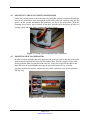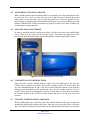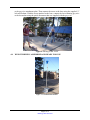
1
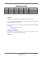
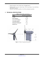
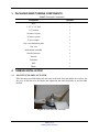
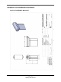
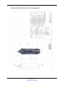
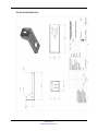
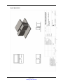
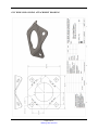
SPIN MICRO WIND TURBINE OPERATIONS AND MAINTENANCE MANUAL Version 1.0 4/25/2014 SPINergy Wind Solutions VERSION HISTORY Version # 1.0 Implemented By Yates Revision Date 4/25/14 Approved By Yates Approval Date 4/25/14 Reason First Edition 1. Preface This Manual applies to the SPIN turbine produced by SPINergy Wind Solutions. It is the responsibility of the turbine owner to only allow knowledgeable and qualified persons to operate the micro-wind turbine. Do not erect and operate the micro-wind turbine before having studied and understanding the following: Safety Measures for Operations User Manual 2. Updating of the Manual This manual will be continuously updated. Corrections to the document will be noted under the “Version History” section of the document. 3. Contents Page 2 of 14 SPINergy Wind Solutions TABLE OF CONTENTS 1 SAFETY MEASURES FOR OPERATION .......................................................................... 3 2 TECHNICAL SPECIFICATIONS ........................................................................................ 4 3 PACKAGED WIND TURBINE COMPONENTS................................................................ 5 4 TURBINE INSTALLATION .................................................................................................. 5 4.1 Mounting blades onto hub ......................................................................................... 5 4.2 mounting yawing system to main frame ................................................................... 6 4.3 mounting hub to generator ........................................................................................ 6 4.4 anchoring of base to ground ...................................................................................... 7 4.5 Nacelle onto main frame ........................................................................................... 7 4.6 Connection of tower sections .................................................................................... 7 4.7 connect tower to base and raise ................................................................................. 7 4.8 Wind turbine is assembled and ready for use ............................................................ 8 5 OPERATIONS OF TURBINE ............................................................................................... 9 6 MAINTENANCE OF TURBINE ........................................................................................... 9 6.1 Monthly ..................................................................................................................... 9 6.2 quarterly .................................................................................................................... 9 APPENDIX A: REPLACEMENT COMPONENTS ................................................................. 9 APPENDIX B: ENGINEERING DRAWINGS ....................................................................... 10 Nacelle Assembly Drawing ................................................................................................... 10 Yawing System Sectional View Drawing ............................................................................. 11 Mainframe Drawing............................................................................................................... 12 Base Drawing......................................................................................................................... 13 Guy Wire Slip on Ring attachment Drawing ......................................................................... 14 1 SAFETY MEASURES FOR OPERATION Read these safety measures in their entirety prior to assembling the SPIN micro wind turbine. Check boxes to indicate safety measures are fully understood. SAVE THE OPERATIONS MANUAL. This manual contains vital instructions that are to be followed to properly assemble, install, and maintain the wind turbine. Read, understand, and follow all warnings. Do not install the SPIN micro wind turbine on a windy day. Properly torque all fasteners during assembly and installation. Turn off the wind turbine if it emits an unusual noise. Page 3 of 14 SPINergy Wind Solutions Properly mark guy wires to make aware of tripping hazard. Rotating blades can cause serious injury. Do not put objects of any kind above safety marker on tower. Ensure the wind turbine assembly is level before putting into operation. 2 TECHNICAL SPECIFICATIONS Table 1: Wind Turbine Specifications SPIN micro wind turbine Model 4.5kg Weight Rotor Diameter 43.7cm Start Up Wind Speed 10m/s Watt Hours/month Maximum Wind Speed 600 17m/s 5W Rated Power Figure 1: Turbine Component Dimensions Page 4 of 14 SPINergy Wind Solutions 3 PACKAGED WIND TURBINE COMPONENTS Table 2: Packaged Components Component Quantity Base 1 3-1/2” x 3/4” bolt 1 3/4” locknut 1 6ft tower section 3 3ft tower section 1 Tower coupler 3 Guy wire attachment plate 1 Guy wire 3 Main frame assembly 1 Nacelle fasteners 6 Nacelle 1 Generator 1 Hub 1 Blade 3 4 TURBINE INSTALLATION 4.1 MOUNTING BLADES ONTO HUB Place the three provided blades into the seats in the hub. Once the blades are in place, put the cover of the hub over the blades and tighten the nut until the blades are secured onto the hub. Figure 2: Blade and Hub Assembly Page 5 of 14 SPINergy Wind Solutions 4.2 MOUNTING YAWING SYSTEM TO MAIN FRAME Attach the yawing system to the main frame by fitting the yawing mechanism through the hole in the main frame. Once through the main frame, place the retaining ring into the groove on the yawing mechanism that protrudes just above the main frame. With the retaining ring in place, put a locknut on the three provided bolts and place in holes for yawing system and main frame. Tighten bolts with a wrench. Figure 3: Yawing System and Main Frame Attachment 4.3 MOUNTING HUB TO GENERATOR In order to mount the blade hub to the generator, the gear box must be attached to the main frame using the supplied M3 bolts with the supplied nuts. Then the couplers for the shaft for the generator must be tightened with a hex key. Lastly, the couple for the shaft to the blade hub must be mated together by using the previously used hex key. After the generator and hub are in place, connect the red, yellow, and black wires for the generator and slip ring. Figure 4: Hub, Gearbox, and Generator Assembly Page 6 of 14 SPINergy Wind Solutions 4.4 ANCHORING OF BASE TO GROUND With a suitable location for the turbine found, it is essential to level the ground for the base to settle into. Use a level to ensure the base is level and if necessary modify the ground with a shovel or any necessary tool to make the ground level. Once the ground is level, place the base in its operating location and anchor the base to the ground with the provided anchors. IMPORTANT: Ensure the anchors are properly in place or the base is liable to tip over during the raising operation. 4.5 NACELLE ONTO MAIN FRAME In order to attach the nacelle onto the main frame, slide the lower part of the nacelle/faired tower section over the sleeve of the yawing system. Then place the upper half of the nacelle onto the bottom half of the nacelle, then tighten with the supplied M3 fasteners. Figure 5: Main Frame and Nacelle Assembly 4.6 CONNECTION OF TOWER SECTIONS Stage the tower sections starting with the single 3ft section followed by the three 6ft sections. Place couplers in between each section. Starting with the 3ft section, place the guy wire attachment plate on top of the tower section and then slide the wire from the yawing system through the tower section and screw the first coupler onto the 3ft tower section. Then run the wire through the 6ft tower section and screw that tower section into the coupler attached to the 3ft tower section. Repeat the process for the next two tower sections. 4.7 CONNECT TOWER TO BASE AND RAISE Before attaching the tower to the base, place the selected anchors for the guy wires into the ground and ensure that the anchors are secure. Once they are secure, place three of the four guy wires onto the anchors and ensure there are no obstructions from the guy wire anchors Page 7 of 14 SPINergy Wind Solutions to the guy wire attachment plate. Then connect the tower to the base using the supplied ¾” bolt and locknut. With the tower attached to the base, connect the last remaining guy wire to the last anchor using the quick disconnect that was supplied with the guy wire. Figure 6: Raising of the Tower 4.8 WIND TURBINE IS ASSEMBLED AND READY FOR USE Figure 7: Assembled Wind Turbine Page 8 of 14 SPINergy Wind Solutions 5 OPERATIONS OF TURBINE Once wind turbine is assembled, be sure that brake is disengaged and enables the blades to turn at safe speeds. Under normal, windy conditions, plug small electronics into plug located on the base to allow the electronics to be charged. 6 MAINTENANCE OF TURBINE 6.1 MONTHLY Inspect base to ensure no rust has accumulated. Check tightness of bolts. Check tension in guy wires. 6.2 QUARTERLY Inspect condition of blades. Ensure battery is functional. Inspect wiring connections. Inspect tower couplers. Inspect generator conditions. Inspect condition of nacelle APPENDIX A: REPLACEMENT COMPONENTS Part Part Number Junction Box RSC080804RC Guy Wires 6ft Tower 3ft Tower Coupler Battery 3498T41 5038K5 5038K38 44705K99 UB12120 (D5775) Page 9 of 14 SPINergy Wind Solutions APPENDIX B: ENGINEERING DRAWINGS NACELLE ASSEMBLY DRAWING Page 10 of 14 SPINergy Wind Solutions YAWING SYSTEM SECTIONAL VIEW DRAWING Page 11 of 14 SPINergy Wind Solutions MAINFRAME DRAWING Page 12 of 14 SPINergy Wind Solutions BASE DRAWING Page 13 of 14 SPINergy Wind Solutions GUY WIRE SLIP ON RING ATTACHMENT DRAWING Page 14 of 14 SPINergy Wind Solutions