1
DC Boarduino/328
A4 (PC4)
A5 (PC5)
DS1307 module
SDA
SCL
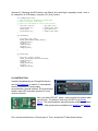
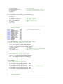
Remember than each data line needs a pull-up resistor. Check your RTC module for these resistors.
Mine uses a pair of 2.2K (red/red/red) resistors. If your module does not include these resistors, install
them on your breadboard between +5V and SDA/SCL. I also tried a pair of 4.7K resistors and they
worked fine.
Boarduino
RTC module
I2C bus
Contrast Adjust
LCD display
Here is the breadboard layout. The I2C bus is represented by the white (SDA) and blue (SCL) wires.
There are two 4.7K pull-up resistors on the bus, which are partially hidden by the four red data lines.
The LCD is a 20x4 character HD44780-compatible display. See my LCD article for more information
on this interface. A 10K potentiometer controls the display contrast.
That’s it. In my next article I’ll show how to interface a more clock-like LED display over I2C.