1
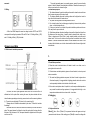
MT100L Ultrasonic Level Meter USER MANUAL Dalian Metery Technology co.,Ltd Ultrasonic Level Meter amend the card’s contents without advance notice. Receipt Acknowledgement of Warranty Card for Ultrasonic Level Meter 7 User’s name Ultrasonic Level Meter Contact address Contact person Tel. Product type Product No. Date of acceptance check Setter in-charge …………………………………………………………………… Notes on Warranty Card for Ultrasonic Level Meter Product type Date of Product No. acceptance check Setter in-charge Warranty policies: Warranty period: The warranty period of products of the company shall last The product or its part is beyond the period of free warranty. Hardware fault caused by that the application environment does not meet the product’s application requirements. 3.2 Wiring……………………………………………………………………………………2 3.3 Definitions of installation parameters……………………………………………………3 3.4 Installation principles……………………………………………………………………3 4.1 Keyboard directives …………………………………………………….…….…………4 4.2 Password directives …………………………………………………….…….………...4 4.3Parameter setting ……………………………………………………….….….…… 4 4.3.1Calibratingof level (P01) ………………………………………………………4 4.3.2Setting of 20mA (P02) …………………………………………………………5 4.3.3 Setting of Relay 1 (P03) ……………………………………………………………5 Faults or damage caused by bad power supply environment or by foreign 4.3.4Setting of Relay 2 (P04) matter’s entering the equipment. 4.3.5Setting of display mode (P05) Faults caused by the operation that is not carried out according to application 4.3.6Probe’s height (P06) ……………………………………………………………6 methods and points for attention stated in the using and operation manual. 4.3.7Setting of ID No. (P07) Faults caused by natural factors and force majeure, such as thunder, flood, and 4.3.8Setting of baud rate (P08) water. 4.3.9Setting of blind area (P09) ……………………………………………………6 Faults or damage caused by dismounting or repair without permission, by 4.3.10Setting of reaction velocity (P10) ……………………………………………6 unauthorized refit, or by abuse 4.3.11 4~20mA testing (P11) ………………………………………………………6 Points on restriction: 3.1External dimension………………………………………………………………………2 4 Debugging…………………………………………………………………………………. 4 3 Installation………………………………………………………………………………….2 3.5 Installation precautions……………………………… …………………………………4 Following cases are beyond the scope of free warranty: 2 Technical data………………………………………………………………………………1 arises because of normal using during the warranty period, the meter will be twelve months since the date of acceptance check. 1 Outline……………………………………………………………………………………….1 The user shall show the warranty card when the meter is repaired. If any fault repaired for free by virtue of the warranty card. CONTENTS The warranty card should be properly kept by the user to be as the warranty certificate. If lost, it won’t be reissued. The company shall own the warranty card’s interpretation power and have the right to ………………………………………………………5 …………………………………………………6 ………………………………………………………6 ……………………………………………………6 4.3.12 Setting of wave generating capacity (P12) …………………………………6 Receipt Acknowledgement of Warranty Card………………………………7 Analog output: 4~20mA Digital output: RS485, Agreement Modbus or custom agreement Power supply voltage: DC24V/AC220V, a built-in lightningproof device Ambient temperature: -20℃ ~ +60℃ Protection grade: IP65 Ultrasonic Level Meter 1. Outline Sincerely thank you for buying our ultrasonic l level meter. 1 Ultrasonic The meter includes several proprietary technologies, is safe and clean, with high precision and long service life, stable and reliable, and convenient to install and Meter maintain, and is applicable to various fields of acid, alkali, salt, anticorrosion, and high 4.3.5 Setting of display mode(P05) Change the display mode by Menu P05. There are 3 display modes available for temperature. The meter can be connected to display meters or various DCS systems through selection: 4~20mA or RS485 (Agreement Modbus or other custom agreements), to provide 1. “H-” displays real-time level data for the operation of industrial automation. 2. “H” displays The meter is with following features: Level For circuit design, high-quality power modules are selected to be as power supply level and the state of the relay; level and temperature; 3. “d” Displays distance (with P before the number) and the state of the relay. Press ▲ to choose the mode needed and then press OK to confirm. parts and highly stable and reliably imported devices are used as components of the meter. It can fully replace imported foreign meters of the same type. 4.3.6 Probe’s height(P06) Patent sonic-wave intelligent technology software can make intelligentized echo By Menu P06, display the probe’s height, check if the probe’s height is in consistent analysis. It needs neither debugging nor other special steps. This technology has with the situation on site, or calibrate the level. Change the probe’s height value based functions of dynamic thinking and dynamic analysis. on on-site situation. Our sonic-wave intelligent patent technology greatly improves the meter’s precision, and the precision of level is up to 0.3%, which is enough to resist 4.3.7 Setting of ID No.(P07) various interference waves. Used when communication is proceeding, especially multi-computer communication is The meter is a non-contact one and does not directly contact , so the fault rate is made. The default is 01. low. The meter can be installed in several different ways, and the user can calibrate the meter according to the Manual. 4.3.8 Setting of baud rate(P08) The meter’s all input and output lines must be with such protection functions as Used when communication is proceeding. Three choices are available: 2400, 4800 and lightning protection and short circuit prevention. 9600. 4.3.9 Setting of blind area(P09) 2. Technical data Measuring range: 0~15m(Chosen based on actual measuring range) Change the meter’s blind area to adapt to some complex situations on site. For Blind area: 0.25m~0.6m example, prevent prominent things around the probe from affecting the meter. Generally, Ranging accuracy: 0.3%(Standard condition) there is no need to change the factory default. Ranging resolution: 1mm Pressure: Less than four atmospheric pressure Meter display: With LCD to display levels or distances 4.3.10 Setting of reaction velocity(P10) The faster the level changes, the quicker the meter is required to react, and the greater the data the meter displays fluctuates; conversely, the reaction velocity is slow, and the data is stable. If the level doesn’t change quite fast, there is generally no need control the draining well and the inlet well. to change the factory default. Corresponding level value or level difference value may be input at the positions of Number 1 and Number 2. 4.3.11 4~20mA testing(P11) For example: “ 3.0 -” P11: 4~20mA test menu. Press OK and then press ▲ to conduct 4~20mA output Relay closes when the level value is over 3.0m. “ 2.0 -” Relay closes when the test. “ 6.0 level value is less than 2.0m. 1.0” The pump is turned on for draining when the level is over 6m and stops when the level decreases to 1m. It is applied to the draining well. 4.3.12 Setting of wave generating capacity(P12) “ 1.0 Set the wave generating capacity, which has been set when delivered and doesn’t 6.0” The pump is turned on for water inflow when the level decreases to 1m and stops when the level rises to 6m. It’s applied to the inlet well. need changing. After setting, press Mode to exit from the setting menu. 4.3.4 Setting of Relay 2(P04) 6 Ultrasonic Level Meter Set Relay 2 in the same way as above. 5 Ultrasonic Level Meter 4.3.2 Setting of 20m(P02) When the meter works normally, press Mode to enter the parameter setting menu. Press ▲to choose P02 menu. The number in the second line is the level corresponding to 20mA. Press OK to set. 3. Installation 3.1 External dimension (The probe’s dimension changes with different measuring range. Any difference will be informed in advance) 4.3.3 Setting of Relay 1(P03) When the relay logic is edited, the twinkling number is the number changeable currently. Press ▲, the number will be changed. Positions A and C: “ ”: More than; “ ”: Less than; Positive B: “ ”: AND, means when the level value simultaneously meets two conditions, the relay closes; otherwise, the relay releases. “|”: OR, means when the level value meets any of the two conditions, the relay close; otherwise, the relay releases. “ - ”: Only under the former condition, Position C and Number 2 will become invisible. It means when the level value meets the former condition, the relay closes; otherwise, the relay releases. “ ”: Under the former condition, the relay closes (generally to turn on pump); under the latter condition, the relay releases (generally to stop pump). It’s mainly used to Installation way: In an open environment, install it with brackets, and fix with the built-in flange. For pools or tanks, make a hole that is a little larger than the probe’s diameter (60mm) at the installation position. Then screw and tighten the flange. The installation must ensure that the probe surface is horizontal to the level measured. 3.2 Wiring 4~20mA and RS485 adopts the same two wiring terminals. SPST1 and SPST2 correspond to the setting of parameters P03 and P04. See 4.3.3 Setting of Relay 1 (P03) and 4.3.4 Setting of Relay 2 (P04) for details. 2 Ultrasonic Level Meter The probe’s generating wave is a spreading process, namely, there are direction angles, to which the attention should be paid in installation. Otherwise, the wave may hit bumps on pool walls or the channel’s edges. 3.4 Installation principles 1)The distance between the probe’s emitting surface and the lowest level must be less than the measuring range of the meter chosen. 2) The distance between the probe’s emitting surface and the highest level must be larger than the blind area of the meter chosen. 3)The probe’s emitting surface must keep parallel to surface. 4)Do not install probe at feed or discharge ports positively below and other positions where surface fluctuates fiercely. 5)If the poor or tank wall is not smooth, the probe’s installation position must be over 0.3m away from the poor or tank wall. 6) I If the distance between the probe’s emitting surface and the highest level is less than the blind area of the meter chosen, it needs to install a extension tube, which is over 120mm in diameter and 0.35m~0.50m in length, installed vertically, and with smooth internal walls. The hole on the tank must be larger than the extension tuber’s inside diameter. Or, the tube touches the tank bottom. The tuber diameter is over 80mm. A hole is made at the tube bottom, so as to the surface inside the tube is the same high as that inside the tank. 3.3 Definitions of installation parameters 3. Ultrasonic Level Meter 3.5 Installation precautions 1) Where the meter is installed outdoors, it’s better to install a sun shied, so as to prolong the meter’s service life. 2)Electrical wires and cable protective pipes must be well sealed, in order to prevent water accumulation. 3)The meter has lightning protection component, but, when it is used in regions where it thunders frequently, it is suggested that a lightning protection device for exclusive use be separately installed at wire inlet and outlet of the meter. 4)If the meter is used at place where it is quite hot or cold, namely ambient temperature may exceed the meter’s working requirement, it is suggested that the high or low As shown, the meter’s probe generates wave, which hits the level and then is reflected back to the probe. After receiving the wave, the probe calculates the time temperature resistance device be set around the level meter. 4. Debugging interval between generating and receiving wave and works out the measuring distance (L). The meter’s mounting height (TH) minus L is the current level (H). Mileage refers to the distance measurable by the meter. TH should be less than the mileage. Blind area refers to the area which cannot be measured by the meter around the probe. The space between the highest level and the probe should be larger than the blind area. If the blind area is 0.3m, the space between the highest level and the probe must be over 0.3m. 4.1 Keyboard directives 【 Mode 】: Menu. Press 【 Mode 】 , the password interface will appear, and input password to enter the menu. When setting, press 【Mode】to cancel the setting; after finishing setting, press 【Mode】 to withdraw from the menu. 【▲】: Page down and number. In menu, the key is used as the page down key of menu; when changing data, the key is used as number key. 【 】: Shift and page up. In menu, the key is used as the page up key of menu; when changing data, the key is used as shift key. 【OK】:Confirmation. Choose menu or confirm option and data. 4.2 Password directives Press key Mode, the password interface will appear: “----------”; press key 【▲】to change the first place into 1, and press key 【OK】to enter the interface of parameter setting menu. 4.3 Parameter setting 4.3.1 Calibrating of level(P01) After the meter is installed and electrified, the value of level will display. The datum is often inconsistent with the actual level, so it needs to calibrate the level. Steps to calibrate the level are as follows: Press Mode, input the password, and then press OK to enter the parameter setting menu. P01 is the press OK to calibrate the (such as 2.100) with level calibration menu; level P01. Change the number into the actual value of level (shift) and ▲ (change number), and press OK to confirm. Then press Mode to exit from the parameter setting menu. Now, it displays 2.100 on LCD screen. 4