1
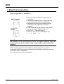
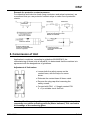
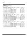
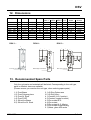
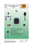
Service Manual
for
Flow Meter / Monitor
Typ: DSV-...
DSV
1. Contents
1.
2.
3.
4.
5.
6.
7.
8.
9.
10.
11.
12.
13.
13
Instructions ......................................................................... 3
Contents ............................................................................. 2
Suggested Application........................................................ 3
Operating Principles ........................................................... 4
Instrument Inspection ......................................................... 4
Mechanical connection ....................................................... 5
Electrical connection........................................................... 6
Commission of Unit ............................................................ 7
Maintenance ....................................................................... 8
Technical Data.................................................................... 9
Ordering Codes ................................................................ 10
Dimensions....................................................................... 11
Recommended Spare Parts ............................................. 11
Declaration of Conformance............................................. 12
Manufactured and sold by:
Kobold Messring GmbH
Nordring 22-24
D-65719 Hofheim
Tel.: +49(0)6192-2990
Fax: +49(0)6192-23398
E-Mail: [email protected]
Internet: www.kobold.com
Seite 2
DSV 12/02
DSV
2. Instructions
Please read this operating instruction carefully before unpacking and set-up.
These devices may be used, maintained and installed only by personnel, who are
familiar to work with operating instructions and can observe appropriate safety
measures.
PED 97/23/EG
In acc. with Article 3 Paragraph (3), "Sound Engineering Practice", of the
PED 97/23/EC no CE mark.
Table 8, Pipe, Group 1 dangerous fluids
3. Suggested Application
These units of type DSV are employed for measurement and monitoring of flow
of liquids.
Only those liquids may be measured which are homogeneous, free from
impurities and have low viscosity. Also, they must withstand against materials
used in fabrication of these units. Media, having high viscosity can introduce
considerable measurement errors (partly).
Large dust particles can block the float, resulting in error-messages and
erroneous measurements. Also, ferrite particles, which deposit on the embedded
magnets of float, can trigger the same effect. To overcome this problem,
installation of a magnetic filter is recommended.
The units are provided as follows:
Flow measurement
The reading of current flow takes place on the spot. Top edge of the float
displays the flow directly in l/min (water) on the scale attached to the graduated
measuring glass.
Limit-contacts (only with type DSV-2... and DSV-3...)
With a view to monitor the flow values, all units are provided with one or two
adjustable limit-contact(s).
Standard version:
Special version:
Special version:
Normally Open function (with increasing flow)
Switch-over function
Ex-contact N.O., Ex-contact switch-over
To a large extent, the contact is adjustable (over the entire measuring range),
while giving due consideration to hysteresis.
DSV 12/02
Seite 3
DSV
4. Operating Principles
The flow meter and monitor of type DSV
operate according to the famous principle of
float flow metery, though, without using
generally employed extended conical
measuring tube. These patented units
incorporate instead a cylindrical lead-pipe,
which has a slit along the periphery of the
cone. Inside this lead-pipe, a float is situated
which lifts up as the liquid rushes into the
pipe. Every float position corresponds to a
definite flow value, which can be read from
scale attached to the measuring glass.
Inside float element, permanent magnets
are embedded, which energise a protective
gas contact (Reed Switch). The triggering
of contact takes place in a non-contacting
fashion (through magnetic force) i.e. the
contact is hermetically separated from
entering medium.
5. Instrument Inspection
These devices are examined before dispatch and sent away in perfect condition.
Should damage to a device be visible, then we recommend an exact check of the
delivery packing. In case of damage please inform the postal service/forwarding
business immediately, since they hold the responsibility for any damages during
transit.
Scope of delivery
Scope of delivery applies to all parts assembled within the unit.
Seite 4
DSV 12/02
DSV
6. Mechanical connection
Before installation:
· Make sure that the permitted max. operational pressure and temperature limits
are not exceeded (see Ch. 10 Technical Data)
· The installation of the unit is rendered vertically in the piping scheme. The flow
should take place from bottom to top.
· Remove all transport safety locks and ensure that no remains of packing
material reside inside the unit.
· The sealing of union fittings is carried out through Teflon band or similar
material.
· During installation of these devices, attention must be paid to the ascertain
that no large course or pressure-load is exercised on the union fittings. We
recommend to fasten the inlet and outlet line at approx. 50 mm distance
mechanically, from the union fittings.
· The units may not be installed at a location within an inductive field.
Note! The union fittings of these devices must be held fixed by means
of a suitable fork-wrench while screwing in. Otherwise stresses will
transfer to the housing which may lead to the destruction of graduated
measuring glass.
· If possible, it should be checked after mechanical installation whether the
connections between union fittings and pipes are properly sealed
Attention! While installing in a free and open environment, please pay
attention to the fact that the freezing of medium can destroy the
measuring tube.
DSV 12/02
Seite 5
DSV
7. Electrical connection
(Only for type DSV-2... and DSV-3...)
· Ascertain, that the electric supply lines are
not active.
· Loosen the stopping screw of plug-cap and
draw off the cap (crown) from plug-base.
· Assemble the power lines inside plug-cap,
according to the adjoining connection
diagram.
· If the contact is not adjusted yet, this should
be done for good reason at this point.
· (see Ch. 8 - "Commissioning").
· Place the plug on the contact base and
f t it ith th
f t
Note! The given electrical parameters of contact may not be exceeded
individually, even for a brief period of time. For higher switching values, we
recommend a protective contact relay or some other contact protection
measure.
After connecting the limit contact with the external devices you wish to
incorporate within the system and adjusting the desirable switching points all
connection work is completed.
The unit can now be put into operation.
Seite 6
DSV 12/02
DSV
Example for protective contact measures.
For capacitive and inductive loads (long conductors and relays/contactors), we
recommend that you use protective contact relays or make use of protective
circuits.
8. Commission of Unit
Application in machines, according to guidelines 89/392/EWG, the
commissioning of these units is barred till it is determined that the machine is in
agreement with the designations of guidelines.
Adjustment of limit-values
· Loosen both the safety screws on the
contact base, with the help of a screw
driver.
· Dislocate the contact base till lower catch.
· Remove the plug-cap after loosening the
safety screws.
· Connect with PIN 1 + 2 (toggle contact PIN
2 + 3) a suitable circuit test unit.
Attention! Sudden opening of the supply can lead to pressure peaks, which
repeatedly exceed the operating pressure (Water hammer!) This can lead to
the breakage of the measuring glass.
DSV 12/02
Seite 7
DSV
Case 1: Device in circuit
Open the supply line.
Let the medium flow slowly, till the
Top edge of the float shows the flow
Volume of desired switching point.
Case 2: Device outside circuit
Raise the float with a suitable tool,
till the top edge of the float shows
the desired flow volume of desired
switching point.
· The reed contact is now closed (electrically closed-circuit).
· Dislocate switch-housing upwards, till the reed-contact is just open (no
electrical passage). The contact is now adjusted for decreasing flow. If the
contact needs to be adjusted for increasing flow, it must be relocated now
around the hysteresis about 3-5 mm downwards.
· Adjust the safety screws in this position by tightening them. Put on plug-cap.
The unit is ready for operation.
· The correct adjustment of limit-contact has the bistable switching behaviour;
i.e. on exceeding the adjusted limit, contact remains closed and below the
adjusted limit, contact stays open.
Hysteresis
Hysteresis reflects the difference between switch-on and switch-off points of
contact. Through standard tuning of magnet and contact pith (AW number) a
hysteresis of about 3-5 mm float stroke is achieved. Thereby, simultaneously
ensuring that the contact exhibits bistable behaviour.
Transgression of measuring range
Attention! Continuous violation of measuring range by pulsating flow
and thereby resulting jerks of float on the limit-pin can lead to
increasing wear and damage to the unit. In such a case, please consult
your supplier.
Non-pulsating flow can essentially exceed the measuring range, merely resulting
in a notable increase in pressure-loss.
(Permitted max. operational pressure not to be transgressed)
9. Maintenance
In case, the medium to be measured is free from impurities, the units of type DSV
are almost maintenance free. If lime or other deposits on measuring glass or
within interior parts develop, the units should be cleaned on a regular basis.
After removing the upper grub-screw, screw joint can be withdrawn from the unit,
and the inner parts can be extracted for cleaning. The measuring glass can be
cleaned with the help of a suitable brush. After cleaning, the unit must be
assembled in the correct sequence.
Seite 8
DSV 12/02
DSV
10. Technical Data
Housing:
Connections:
Float:
Orifice:
Measuring glass:
Sealings:
Max.temperature:
Max. pressure:
Accuracy:
Mounting position:
Weight:
Pressure loss:
Aluminium anodised (no contact with Medium)
DSV-x1..: Brass MS 58, Ni-plated
DSV-x2..: St. Steel 1.4301
see Ch. 11 Dimensions
DSV-x1..: Brass MS 58, Ni-plated
DSV-x2..: St. Steel 1.3955
Duran 50 (Borosilicate glass)
DSV-x1..: Perbunane
DSV-x2..: Viton
100 °C (Metal-float)
70 °C (PP or PVDF float)
10 bar
± 4% (F.S.)
vertical, flow from bottom
see Ch. 11 Dimensions
see Ch. 11 Dimensions
Contacts (DSV-2..., DSV-3...)
Electrical Switching parameters
N.O contact (CSA)
max. 240 VAC / 100 VA / 1.5 A
Changeover contact (CSA)
max. 240 VAC / 60 VA / 1 A
N.O. EEx d llC T6
max. 250 VAC / 80 VA / 2 A
Changeover EEx d llC T6
max. 250 VAC / 60 VA / 1 A
N.O. EEx ia l BVS. (Mining)
max. 250 VAC / 100 VA / 1.5 A
Changeover EEx ia BVS
(Mining)
max 220 VAC / 60 VA / 1A
Electr. Connection:
Plug DIN 43 650
Except DSV-..E..; DSV-..X..:
1.5 m cable
Protection cat.:
IP 65
DSV 12/02
Seite 9
DSV
11. Ordering Codes
Seite 10
DSV 12/02
DSV
12. Dimensions
Type
SW
G
L (mm)
D (mm)
DSV-..01H
DSV-..02H
DSV-..03H
DSV-..04H
DSV-.. 05H
DSV-..06H
DSV-..O7H
DSV-..08H
DSV-..09H
32
32
32
32
32
41
41
41
46
¼(½)
¼(½)
¼ ( ½)
½(¾)
½(¾)
¾ (1)
¾ (1)
1
1¼
161 (165)
161 (165)
161 (165)
165
165
165 (176)
165 (176)
204
222
43
43
43
43
43
48
48
48
55
DSV-1...
Weight approx. (kg)
DSV-1 DSV-2 DSV-3
0.75
1.0
1.25
0.75
1.0
1.25
0.75
1.0
1.25
0.75
1.0
1.25
0.75
1.0
1.25
1.0
1.25
1.5
1.0
1.25
1.5
1.2
1.45
1.7
1.5
1.75
2.0
DSV-2...
dP
bar
0.04
0.06
0.04
0.04
0.07
0.08
0.14
0.3
0.4
Float with unit version
Brass
St.Steel
PP
PVDF
PP
PVDF
PP
PVDF
PP
PVDF
MS Ni-pl.
1.4301
PP
PVDF
MS Ni-pl.
1.4301
MS Ni-pl.
1.4301
PP
PVDF
DSV-3...
SW
30
30
43
43
SW
L
L
L
SW
Both edge connection
D
Both edge connection
Both edge connection
D
D
13. Recommended Spare Parts
Only the unit-parts and materials will be listed. Corresponding to the unit type,
parts in different sizes are available.
(Please ensure you mention the unit type, when ordering spare parts).
1.1) Float Brass
1.2) Float Polypropylene
1.3) Float St. Steel
1.4) Float PVDF
2.1) Slit-orifice Brass
2.2) Slit-orifice St. Steel
DSV 12/02
3.1) O-Ring Perbunane
3.2) O-Ring Viton
4.1) Contact (N.O. function)
4.2) Contact (toggle function)
4.3) Ex-contact N.O.
4.4) Ex-contact
4.5) Ex-contact N.O. Mining
4.6) Ex-contact toggle Mining
5.1) Meas. glass with scale
Seite 11
DSV
13 Declaration of Conformance
We, KOBOLD-Messring GmbH, Hofheim-Ts, Germany, declare under our sole
responsibility that the product:
Flow Meter / Monitor Type DSV-...
is in agreement with the following standards:
DIN EN 61010-1
1994-03
Safety requirements for electrical equipment for measurement, control and
laboratory use.
DIN VDE 0470-1
1992-11
Protection through housing (IP-code)
Also the following EWG guidlines are fulfilled:
73/23 EWG
Signature:
Date: 30.09.02
H. Peters
Seite 12
M. Wenzel
DSV 12/02