1
BLCDP-6M12LT-2RFID-A-8DI-PD
10 Parameters
10.1 PROFIBUS-DP Parameter
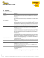
Parameter
startup when expected/actual
config. differ
static configuration
outputs fieldbus error
outputs mod. sequence error
outputs mod. sequence error
integer data format
• 2010-6-18
diagnostics from modules
14 / 62010
Description
0 = activated *)
Reaction depending on the parameter „Bit 6: Static configuration”. If the static configuration is deactivated, the process data exchange is not disturbed in case of module sequence error.
1 = deactivated
Reaction depending on the parameter „Bit 6: Static configuration”. If the static configuration is activated, the process data exchange is not disturbed in case of module sequence
error.
0 = activate *)
Changes in the station configuration are stored in the gateway following a power-on.
1 = deactivate
If the static configuration is deactivated, a dynamic configuration take-over is realized directly following station configuration changes (important for acyclic parameterization).
The station stops the process data exchange and the bus communication as soon as a
module sequence error appears, ignoring the parameterization for error handling. But,
the communication is not interrupted, if the gateway-parameter byte 1, bit 0 "startup.
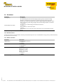
0 = output 0 *)
The gateway switches the outputs of the modules to "0”. No error information is
trans-mitted.
1 = output substitute value
The gateway switches the outputs of all modules (with the exception of analog output
modules) to "0”. Error information is transmitted to the analog output modules. Depending on their configuration, these modules set their outputs either to "0” or to a default
value, or maintain the original values. The non-configured analog output modules set
their outputs to "0”.
2 = hold current value
The gateway maintains the actual output settings of all modules (with the exception of
analog output modules). Error information is transmitted to the analog output modules.
Depending on their configuration, these modules set their outputs either to "0” or to a
default value, or maintain the original values. The non-configured analog output modules maintain their current output settings.
0 to 2, see above "outputs fieldbus error"
3 = Exchange process data
The gateway carries on exchanging process data with the other module bus stations. No
error information is transmitted.
0 to 3, see above "outputs mod. sequence error"
0 = LSB first *)
Data is converted to INTEL format (standard format).
1 = MSB first
16-bit data are transmitted with the high and low bytes reversed (MOTOROLA format).
This parameter influences the process data!
0 = activate *)
Diagnostic messages from the module bus stations are made known to the fieldbus master as extended diagnostics.
1 = deactivate
Diagnostic messages from the module bus stations will not be displayed. A station diagnostic is not automatically generated along with module diagnostics.
Hans Turck GmbH & Co.KG ñ D-45472 Mülheim an der Ruhr ñ Witzlebenstraße 7 ñ Tel. 0208 4952-0 ñ Fax 0208 4952-264 ñ [email protected] ñ www.turck.com