1
Table of Contents
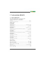
1. How to use this documentation effectively ....................................... 7
1.1
Use for the intended purpose ............................................................................. 7
1.2
Safety information .................................................................................................. 7
1.3
Warranty and liability ............................................................................................. 8
1.4
Explanations of symbols and warnings ........................................................... 8
2. Function .................................................................................................... 9
2.1
General characteristics .......................................................................................... 9
2.2
Essential functions of the A-ISOMETER® ......................................................... 9
2.3
Essential functions of the Insulation fault location system (EDS) .......... 9
2.4
Product description .............................................................................................. 10
2.5
Function .................................................................................................................... 10
2.5.1
2.5.2
2.5.3
2.5.4
2.5.5
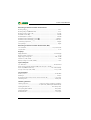
Current output for external measuring instrument .................................. 11
Real-time clock ....................................................................................................... 11
Insulation fault location ...................................................................................... 12
Interconnected systems ...................................................................................... 12
Function input F1/F2 for connection or disconnection
of IT systems being monitored ......................................................................... 12
ISOnet function for central control of the insulation monitoring
process when several IRDH575 are interconnected in IT systems. ...... 14
Self test ...................................................................................................................... 15
Relay K3: device fault alarm and EDS common message ....................... 17
Factory setting ........................................................................................................ 17
2.5.6
2.5.7
2.5.8
2.5.9
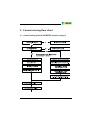
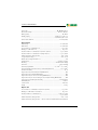
3. Commissioning flow chart .................................................................. 19
3.1
Commissioning of the A-ISOMETER® function range (1) ........................ 19
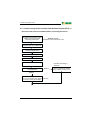
3.2
Commissioning of the insulation fault location function (EDS) (1) ..... 21
TGH1364en/04.2007
3