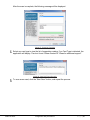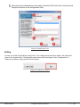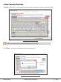
1
Configuration Utility User Manual pcProx® Plus, pcProx® Enroll & Wiegand Converter ©2015 RF IDeas Configuration Utility User Manual 99009010 Rev B2 Page |1 Thank You! Congratulations on the purchase of your pcProx® Enroll, pcProx® Plus, or Wiegand device(s). RF IDeas hopes you enjoy using the readers as much as we enjoyed creating and developing them. Configuration is easy, so you will be able to quickly take advantage of a more secure environment in your business, school, or organization. Please call our Sales department if you have any questions or are interested in our OEM and Independent Developer’s programs. We look forward to your comments and suggestions for our product line! Please go to www.RFIDeas.com and follow the Support Learning Center link for more details about our product line. We are always discovering new applications for our product line(s). There are several software developer’s licensing our technology so the solution you are looking for may already be developed. Thank you, The RF IDeas Staff Need Assistance? Phone: +1 (847) 870 - 1723 Toll Free: (866) 439 - 4884 Fax: (847) 483 - 1129 Email: [email protected] Support: [email protected] ©2015 RF IDeas Configuration Utility User Manual P a g e | ii Glossary of Terms Terms ASCII Contactless FAC OEM pcProx SDK CSN UID Definitions The American Standard Code for Information Interchange codes represent text in computers, communications equipment, and other devices that use text. The high frequency 13.56 MHz smart card technology. Facility Access Code. The card and badge reader without case. Available in self-contained modules for easy system integration. The RF IDeas brand name given to all 125 kHz proximity and 13.56 MHz contactless smart card readers. Software Developer’s Kit. Software Developer’s Kits from RF IDeas provide the high level command capabilities to integrate software applications with our devices. Also known as the Card Serial Number, is part of the ISO 15693 standard for vicinity cards operating at the 13.56 MHz frequency. The User ID or User Identification, can be encoded as data on the card when a security key is needed. Information Symbols Symbol Meaning Note Tip Important ©2015 RF IDeas Definition Notes are useful information related to the text. Tips can provide hints and pointers in addition to the text. Important information can include prerequisites, limitations, and caution. Configuration Utility User Manual P a g e | iii Contents Device Menu ............................................................ 13 Navigation Menu ...................................................... 20 View Menu ............................................................... 20 Glossary of Terms .............................................. iii Card Analyzer Menu ................................................ 22 Information Symbols .......................................... iii Chapter 1. 1.1 The Basics ...................................... 1 Wireless Identification Overview ................. 1 Help Menu ............................................................... 34 3.4 Connect ................................................................... 35 pcProx® Activated Identification ................................1 1.2 ID Card Reader System .............................. 1 1.3 Output Formats ........................................... 2 1.4 Credential Form Factors.............................. 3 1.5 Manufacturer/Vendor Card Compatibility .... 3 1.6 Reader Configuration Purposes .................. 4 1.7 Difference Between pcProx Plus and NonPlus Reader .............................................................. 4 Chapter 2. Hardware ......................................... 5 2.1 What’s in Your Part Number? ..................... 5 2.2 Interface (Connectors)................................. 6 Disconnect ............................................................... 37 Write Settings/Write Active ...................................... 38 3.5 pcProx Plus Configuration ........................ 39 3.6 Connect Tab ............................................. 40 Output Test Area ..................................................... 42 Status Bar ................................................................ 43 3.7 Timing Tab ................................................ 43 3.8 SDK Tab.................................................... 44 3.9 Format Tab ............................................... 48 Data Format Tab ...................................................... 48 Delimiters Tab .......................................................... 50 Connectors .................................................................6 Extended Tab .......................................................... 53 Output ........................................................................7 2.3 USB Readers and Wiegand Converters ..... 7 2.4 RS-232 Readers and Converters ................ 7 2.5 Minimum System Requirements ................. 8 2.6 Reader Setup Basics................................... 8 2.7 LED.............................................................. 8 2.8 Beeper ......................................................... 9 Chapter 3. Software ........................................ 10 3.1 pcProx Configuration Utility ....................... 10 3.2 Utility Overview .......................................... 10 3.3 Menu Toolbar ............................................ 11 File Menu ................................................................. 11 Icon Toolbar .............................................. 35 Hashing Tab ............................................................ 71 Chapter 4. Tips and Troubleshooting ........... 74 4.1 Troubleshooting ........................................ 74 4.2 Precautions ............................................... 75 4.3 Before You Call Technical Support ........... 75 4.4 Talking To the Technician ......................... 75 Index ……… ...................................................... 78 Appendix …. ...................................................... 79 Standard 26-Bit Format Structure ............................ 79 Use the pcProx Device for Password Security Complex Passwords ................................................ 80 Other Products & Accessories ......................... 81 Connect Menu .......................................................... 12 ©2015 RF IDeas Configuration Utility User Manual P a g e | iv Chapter 1. The Basics 1.1 Wireless Identification Overview pcProx® Activated Identification Employers are more security conscious than ever. More buildings, machines, systems, and applications require identification information to gain access. RF IDeas devices allow the building access cards to be used as a digital identifier throughout the workplace. Various pcProx applications include: Card enrollment Application log-on Form filler to existing software applications PC/LAN log On Cafeteria purchases/vending Machine access PLC and embedded controllers Time/attendance Our pcProx Plus devices are easily configured to increase security and reliability. Companies using proximity and/or contactless technology for building access immediately benefit, as their employee identification cards can also be used with the proximity/contactless device for additional authentication applications. Thus, the majority of deployment and enrollment costs are quickly recovered. 1.2 ID Card Reader System The diagram on the following page is a high level overview of how the reader works. The reader sends RF signals to the card and the card sends signals back to send data. The card data is output by the reader in keystrokes or ASCII characters. This card data can be configured to include delimiters to separate the data. This reader can be used as a standalone system or seamlessly integrated with other software applications using the optional Software Developer’s Kit (SDK). ©2015 RF IDeas Configuration Utility User Manual Page |1 Image 1: Card Reader Overview 1.3 Output Formats Image 2: Output Formats ©2015 RF IDeas Configuration Utility User Manual Page |2 1.4 Credential Form Factors Credentials are inactive electronic devices that rely on readers to supply the required power for start-up and communication. The credential itself, consists of antennas that produce proximity or contactless frequencies. Proximity and contactless smart card technology cards allow users to effortlessly manage multiple applications through a single credential. Data: The data on access cards are a string of binary numbers set with a fixed configuration and length. Frequencies: RF IDeas’ access control readers and credentials utilize the low-frequency 125 kHz (proximity) band and/or the high-frequency 13.56 MHz (contactless) band. Credential Form Factors: With over 300 million physical access credentials in use worldwide, there are a variety of low and high frequency form factors, customers can choose from to meet their particular needs. Image 3 illustrates some of the various form factors available: Image 3: Available Form Factors 1.5 Manufacturer/Vendor Card Compatibility Please go to www.RFIDeas.com for specific device part numbers associated to card types. ©2015 RF IDeas Configuration Utility User Manual Page |3 1.6 Reader Configuration Purposes The method of encoding data on a card and transmitting data to the reader differs accordingly in each technology involved. The reader itself is not aware of the makeup of the card data format or access privileges for the cardholder. This information is only accessible through the configuration process of the reader utilizing the supplied software. The reader is very flexible and may need to be configured in order to present an exact desired output for the user, such as, singling out FAC or ID, obtaining a desired base (i.e. decimal, lowercase, upper- case, hexadecimal). 1.7 Difference Between pcProx Plus and Non-Plus Reader The pcProx Plus is a dual frequency programmable reader that combines 125 kHz and 13.56 MHz technologies into the same reader. It’s the only reader in the industry that reads two cards of your choice among more than 45 different card types, delivering flexibility to any customer struggling with different card technologies. In contrast to the pcProx Plus reader, our standard pcProx Enroll proximity and contactless readers function on a single frequency band, which is either 125 kHz proximity or 13.56 MHz contactless. ©2015 RF IDeas Configuration Utility User Manual Page |4 Chapter 2. Hardware 2.1 What’s in Your Part Number? All RF IDeas reader part numbers follow a distinct system of categorization to allow for an ease of differentiation between products. Below is the basic part number scheme: Image 4: Reader Part Number Scheme Device Type: The device type distinguishes between Standard Reader (RDR), Wiegand Converter (OEM), Converter (C), Kit (KT), or Mag Stripe Reader (MS3). Frequency: RF IDeas' badge readers are available in low-frequency 125 kHz proximity (6), highfrequency 13.56 MHz contactless (7), or dual with both 125 kHz and 13.56 MHz technologies (8). Card Compatibility: The card type allows for the selection of over 45 different card types for reader compatibility. (Please visit www.RFIDeas.com, choose a product and locate the Part Numbers (SKUs) tab for specific device part numbers associated to card types.) Housing: Various form factor housing options exist for RF IDeas' readers. The housings include; Desktop (8), Surface Mount (W), USB Dongle (D), PCMCIA (P), Non-Housed (N), ExpressCard (E), or custom (call Sales for custom housing). (For more on form factors, please visit www.rfideas.com/products/readers, click your appropriate reader and select the Data Sheets tab.) Model: The model selection corresponds to the type of reader, whether it is a Standard "Keystroker" (1), SDK (2), Writer (0), or Playback (5). (For more on model types, visit www.rfideas.com/products/readers) ©2015 RF IDeas Configuration Utility User Manual Page |5 Version: The version refers to the selection of either our Standard (A) or Custom builds. (For more on Custom builds, call our Sales department at (866) 439 - 4884). Housing Color: The color category simply allows for the selection of either our Black (K), Pearl (P), White (W), or Gray (G) housings. (Colors are not available in all housings.) Interface: This option specifies the type of connection for the reader. Connectors include: Ethernet ASCII (E), Ethernet ASCII PoE (E-P), E/IP PoE (B-P), ExpressCard (U), PCMCIA (P), Serial 5V Ext Power RS232 (8), Serial 5V Pin9 RS232 (5), Serial 5V PS2 RS232 (2), Serial 5V USB Power Tap RS232 (9), Serial 9V Pin9 RS232 (6), USB (U), USB CDC Virtual COM (0). 2.2 Interface (Connectors) Connectors Connectors include: Image 5: Connector Types ©2015 RF IDeas Configuration Utility User Manual Page |6 Output Output includes: Image 6: Output Types 2.3 USB Readers and Wiegand Converters The pcProx USB keystroke device operates in two primary modes: 1. USB keyboard. It reads the card data and sends it as keystrokes as if the user typed the ID data on a keyboard. 2. Under the application programmer interface (API) defined in the pcProx SDK. When it reads card data, the active application receives the entire card data. T The pcProx ExpressCard operates as a USB reader. 2.4 RS-232 Readers and Converters The RS-232, Ethernet, or virtual COM port device operates in two primary modes: 1. ASCII output device. In this mode the user card data is read and sent as a decimal or hexadecimal number in ASCII characters. 2. API defined in the pcProx SDK. The device attaches to a computer serial port. When it reads card data, the active application receives the entire card data. The pcProx PCMCIA operates as an RS-232 reader. ©2015 RF IDeas Configuration Utility User Manual Page |7 2.5 Minimum System Requirements Components Hardware Memory Disk I/O Operating System Minimum System Requirements Pentium Class PC 64 MB RAM 650 MB Hard Disk Space 1 available RS-232 or USB Port Any operating system that supports a USB keyboard including Microsoft Windows 2000®, XP®, Vista®, 7®, 8®, 8.1®, 8.2®, Server 2003®, and Server 2008®. The software does not perform any data validation checking. The data must be known before it is read to verify its validity. 2.6 Reader Setup Basics To setup the reader: 1. Plug the connector into the workstation’s (or available on any peripheral) open RS-232, USB, or Ethernet plug. 2. Place the device next to the monitor, beside the workstation, or where appropriate. 3. The workstation should detect new hardware for USB connections. Verify the workstation recognizes this connection using Device Manager. 4. Verify the correct COM port for RS-232 DB9 connections using Device Manager. When the software is installed, it should recognize these connections in order to configure the appropriate device. Once the device is configured and written to its flash memory, these settings will not have to be configured again. 2.7 LED The desktop, USB dongle, surface mount, and non-housed model readers are all equipped with a light up LED on the front cover. ©2015 RF IDeas Configuration Utility User Manual Page |8 2.8 Beeper To allow the device to produce a beep when a credential is detected by the reader. The LED and Beeper are configurable through the utility software. (See LED and Beeper functions in the Software section) ©2015 RF IDeas Configuration Utility User Manual Page |9 Chapter 3. Software 3.1 pcProx Configuration Utility The pcProx Configuration Utility provides users with the ability to configure their pcProx Enroll, pcProx Plus, or Wiegand devices to meet their needs. Through the configuration process, desired credential data output and access privileges for cardholders can be established. In contrast to the pcProx Enroll readers, for which only one configuration can be programmed into the reader, the utility allows the pcProx Plus configuration process to create two separate configurations for users. RF IDeas pcProx Plus readers with extended functionality uses two modes “Standard” ID processing or the “Extended” ID processing for output generation. The default mode of processing is Standard mode. The RF IDeas pcProx Plus readers with extended functionality broadens the ability to manipulate card data, output card data in a variety of codes and increase security with data encryption. These highlyconfigurable readers help organizations leverage their existing card technology, streamline the enrollment process, and also provides options for increasing security. 3.2 Utility Overview Image 7: Utility Overview ©2015 RF IDeas Configuration Utility User Manual P a g e | 10 3.3 Menu Toolbar Image 8: Menu Toolbar The Menu toolbar contains all the basic configuration options for the utility. File Menu Image 9: File Overview The file menu entry will only be enabled for USB readers, and not for serial readers. The File menu lists the options for Opening .hwg and saving .hwg files. For pcProx Plus reader, all configurations need to be written to the file. The configuration numbers should be labelled as 1 through N to match the pcProx Config app. Open hwg/hwg+ file…: Opens either an .hwg or .hwg+ file. An .hwg or .hwg+ file contains all the configuration settings for the reader. The utility comes with sample .hwg/.hwg+ files. Save device data to hwg+ file: Saves the configuration settings to the reader. What is an .hwg/.hwg+ file? There are two kinds of configuration files - an .hwg file, and an .hwg+ file. An .hwg file can only be created with previous pcProx application utility version. An .hwg+ file can only be saved using this new utility. An .hwg+ can configure a pcProx Plus reader as well as a single configuration reader. Install libusb for NTWCC Reader: Installs the libusb-Win32 port of the USB library if it is not on the system. It’s necessary to install libusb because a different communication protocol is used by NTWCC readers. ©2015 RF IDeas Configuration Utility User Manual P a g e | 11 What is libusb? “libusb-win32” is a port of the USB library. The library allows user space applications to access many USB devices on Windows. Save USB device hex raw data to (SDK) file…: A USB raw feature report dump to an ASCII text file. Save USB device hex raw data to (SDK) file option is enabled for USB readers, not for serial and NTWCC readers. All bytes are displayed as upper case hex digits, with one space between the hex bytes. Exit: Exits out of the entire utility. Connect Menu The Connect menu provides options for device to utility connections. Auto Connect to USB on Start-up: Set as utility default connection. Through this connection the utility searches for a USB connection on startup. Auto Connect to Serial on Start-up: With this selection, the utility searches for any available serial connections on startup. Auto Connect to Ethernet on Start-up: Utility option to search for Ethernet connections on startup. Why use the Auto Connect feature? Provides easy access to all the available readers on the specified port during application start-up. Connect: This selection has the utility search for a device connection through all available port connections. Why use the Connect feature? The utility’s general connect option gives users the ability to connect their device to the utility, without the need of the user to identify the devices actual interface connection. This feature cycles through all available interfaces until a device is found. For further information on the connect option, see 3.4 Icon Toolbar, under the Connect section. ©2015 RF IDeas Configuration Utility User Manual P a g e | 12 Connect to USB: Connects to current specified reader through USB. Connect to Serial: Connects to current specified reader through serial. Connect to Ethernet TCP/IP: Connects to current specified reader through Ethernet TCP/IP. Why use the Connect to feature? The Connect to feature allows the utility to connect to a device through the specified port upon selection. This is especially helpful when users are switching out and changing devices with different connections. Disconnect: Disconnects all connected devices from every available interface connection from the configuration utility. For further information on the disconnect option, see 3.4 Icon Toolbar under the Disconnect section. Device Menu The Device menu lists the options for resetting, writing to, and reading the device’s configuration. The device menu options are altered depending on the type of device that is connected. A single configuration reader device has different device menu options than a two configuration reader device. Single Configuration Readers Image 10: Device Menu for Single Configuration Readers 1. Reset to Factory Defaults: Resets all configuration parameters to factory defaults. 2. Read Settings: Displays the current connected device configuration. 3. Write Settings: Writes the current configuration settings to the connected device. ©2015 RF IDeas Configuration Utility User Manual P a g e | 13 For more information on the Write Settings option, see 3.4 Icon Toolbar under the Write Settings/Write Active section. For more information on the Clone selected reader configuration to other devices option, refer to the next page. pcProx Plus - 2 Configuration Reader Image 11: Device Menu for pcProx Plus -2 Configuration Readers Reset to Defaults: Resets all configuration parameters to defaults. Defaults are set as HID Prox and RDR-758x Equivalent (covers 5 different card types; HID iCLASS CSN, ISO 14443A CSN, ISO 15693A CSN, MIFARE CSN, MIFARE DESFire CSN). Reset to Stored Settings: This selection allows users to reset the device to their own personally defined stored settings. Write Stored Settings: Writes the current configuration settings to stored settings. Stored settings are defined as configuration settings created by a user and set/written to the device through the utility as a stored settings. Read Active: Reads the current configuration. Active settings are what allow the device to function. Write Active: Writes the current configuration to active settings. For more information on the Write Active option, see 3.4 Icon Toolbar under the Write Settings/Write Active section. Device Menu options are altered when a two configuration device (pcProx Plus) is connected to the utility. Clone Reader Configuration ©2015 RF IDeas Configuration Utility User Manual P a g e | 14 The cloning feature clones the current device configuration settings to other devices. Functions Only update readers within the LUID range Descriptions Check to filter which devices will be cloned. Uncheck to clone all devices. Minimum LUID Minimum LUID value to filter a range of devices to be cloned. Default is 0x0000. Maximum LUID Maximum LUID value to filter which devices will be cloned. Default is 0xFFFF. Write LUID Check to write a new LUID to the device after cloning. Starting LUID The next LUID value to be written. Default is 0x1000. Increment by Adds Increment by value to the LUID after writing to the device. Default is 0x0001. Default Log Clear Log Reset the fields to their default value. Logs of cloning process. Clears all log info from Log area. To enter LUID value in hex use ‘0X’ prefix. To initiate the cloning process: 1. Connect to the reader and click the “Connect” button. 2. Under the “Device” menu, click “Clone selected reader configuration to other devices…” option. Image 12: Starting the Cloning Process 3. The “Clone Reader Configuration” dialogue box will appear as shown below: ©2015 RF IDeas Configuration Utility User Manual P a g e | 15 Image 13: Clone Configuration Reader Dialogue Box The range displayed in the Minimum LUID and Maximum LUID fields will only come in effect when the “Only update readers within the LUID range” option is selected. Starting LUID and Increment by fields will be written in the new readers only when the Write LUID field is checked. ©2015 RF IDeas Configuration Utility User Manual P a g e | 16 4. Disconnect the reader. Image 14: Reader Disconnected You have approximately 18 seconds after disconnecting the reader to connect the readers to be cloned. ©2015 RF IDeas Configuration Utility User Manual P a g e | 17 If there are multiple readers that will be connected to undergo the cloning process, it is suggested that a hub be used for the readers to be cloned. See the following image. Image 15: Reader Disconnected 5. Connect the reader(s) that will be undergoing the cloning process. Image 16: Connecting Other Readers More than one reader can be configured. Configuration must be done one reader at a time. ©2015 RF IDeas Configuration Utility User Manual P a g e | 18 Image 17: Connecting Second Reader Once the configuration process has finished, the below message will be displayed. Image 18: Configuration Finished 6. Click the “Close” button to close the “Clone Reader Configuration” dialogue box. 7. Click the “Connect” button in the “Configuration Utility” to check the new cloned configuration of the connected readers. ©2015 RF IDeas Configuration Utility User Manual P a g e | 19 Navigation Menu The Navigation menu gives users the ability to navigate in and out of the utility tabs through the use of hot keys. This menu lists the hot key commands for the tabs as seen on the Standard Configuration Area (an explanation of each tab can be found in the Standard Configuration Area section of this manual). For example, pressing the F5 key on the keyboard will open the Data Format sub-tab: Image 19: Navigation Menu Hot Keys A Test App hot key command is also available in this list. This command opens any keystroking capturing program (i.e. Notepad, WordPad etc.) in a new window. The Test App default opening program is set as Notepad. View Menu The view menu provides options for altering the appearance of certain functions of the application utility. All the options in this menu are set to appear by default. Show Tooltip Balloon: Menu option for displaying or not displaying the tooltip pop-up balloon. Tooltip balloons appear automatically, or pop up, when the user hovers over a tool or other UI element. The tooltip appears near the pointer and disappears when the user moves the pointer away from the tool, or simply waits for a few seconds. The tooltip displays descriptive information of the specific element or tool that the mouse is currently hovering over. Show Text under Toolbar Icons: Provides option to display or remove text under icons in the Icon Toolbar (for more information on the Icon Toolbar, see 3.4 Icon Toolbar section of this manual). Show Pop-Up Warning Dialogues: Gives option for user to display or remove warning pop-up dialogue boxes. For example, if the Show Pop-Up Warning Dialogues option is selected, then a warning dialogue box, as seen below, will display on your screen. The below warning dialogue box has been displayed to alert the user that the utility has not detected a connected device. ©2015 RF IDeas Configuration Utility User Manual P a g e | 20 Image 20: Pop-Up Warning Dialogue Example Show Confirm Dialogue: Menu option for displaying yes/no confirmation dialogues before certain utility operations are completed. For example, if the Show Confirm Dialogue option is selected, a confirmation dialogue window will appear when a user clicks to reset their device to factory defaults. If the Show Confirm Dialogue option is not selected, all utility operations will continue upon user selection without the need for confirmation. Beep on Warnings: Provides an audible system beep when warnings are detected. With the Beep on Warnings option, the audible beeps will sound even if the Show Pop-Up Warning Dialogues option is not selected. Resize Window: The utility window is designed for users to optionally resize, by making the window larger or smaller (the smallest resize choice will eliminate the view of the Output Test Area). If a user resizes the utility window, clicking this Resize Window option will resize the window to its original size. ©2015 RF IDeas Configuration Utility User Manual P a g e | 21 Card Analyzer Menu The Card Analyzer makes it easy to learn and analyze a card in order to configure a reader. The Card Analyzer comes in handy especially when setting up a new reader system or issuing new cards. The Card Analyzer will quickly learn the card, then allow the reader to be configured based on the analysis of the card. The Card Analyzer also makes it easy to configure and write custom card IDs. It is possible to configure a card from the main utility, but leading/trailing parity and number of bits for the ID are required. ©2015 RF IDeas Configuration Utility User Manual P a g e | 22 To begin, navigate to Card Analyzer from the menu on the utility. Image 21: Card Analyzer Menu The Card Analyzer utility supports pcProx® Plus RDR-80581AKU or RDR-80081AKU readers only. Detecting the Reader The Welcome screen provides a brief introduction, and provides the reader connection status. Image 22: Detecting the Reader Function Status Back Learn Card Exit Description The status may display the following: “Reader not connected”. Ensure the reader is connected properly. “Incorrect reader connected, The Card Analyzer feature is only compatible with pcProx® Plus Readers (RDR-80081AKU or RDR-80581AKU). “Reader connected”. By default, this button is disabled in the welcome screen. Press to transition to the Learn Card screen. This button becomes active only when connected to the correct reader. Close the Card Analyzer and return to pcProxConfig window. ©2015 RF IDeas Configuration Utility User Manual P a g e | 23 Learning Card After the reader is detected, proceed to Learning Card process. This is where the Card Analyzer will attempt to learn the type of card by scanning for matches. Each screen of the Card Analyzer also gives a general overview of the process, and the steps being performed in each phase of the utility. The first part is the scanning phase, where the application will scan the card for matches. Image 23: Learn Card Screen Field/Button Card Type Supporting Readers Start Scan Halt Scan Back Auto Config Description Card type matches are displayed here. Displays the supported RF IDeas readers when a card type is selected. Start the scan function. Stop the scan. This button becomes active after the “Start Scan” button is pressed, and the scanning starts. By default, this button is disabled on this screen. Takes the user to the “Auto Config” screen. This screen allows the user to configure the reader using the default Card Type settings. This button has the following functions – Exit ©2015 RF IDeas If the user has not written configurations, pressing the “Exit” button will return user to pcProx utility without making any changes. If the user has written configurations, pressing the “Exit” button will return user to pcProx utility with new card settings. Configuration Utility User Manual P a g e | 24 Every time the Start Scan button is pressed, the application scans for the Contactless 13.56 MHz, and Proximity 125 KHz Card Types. To learn a card: The application saves the current reader settings prior to scanning. They are restored if the user exits without writing the discovered settings. Click the “Start Scan” button. The “Pop-up Window” appears. Image 24: Starting the Scan The “Back” button is disabled and the “Auto Config” button is unavailable during scanning. ©2015 RF IDeas Configuration Utility User Manual P a g e | 25 When prompted, place a card on the reader, click the “OK” button. Image 25: Placing the Card The analyzer will begin scanning the card for potential card type matches. Matches are displayed in the “Card Type” field. Image 26: Scanning Process “Start Scan” button will be unavailable during the scan process. User can use the “Halt Scan” button to stop the scan process. ©2015 RF IDeas Configuration Utility User Manual P a g e | 26 After the scan is complete, the following message will be displayed: Image 27: Scanning Complete Select any card type to view the list of supporting readers. If no Card Type is detected, the application will display “Card not found: Please contact RF IDeas for additional support”. Image 28: Card Not Found Scenario To scan a new card, click the “Start Scan” button, and repeat the process. ©2015 RF IDeas Configuration Utility User Manual P a g e | 27 To configure the reader, click the “Auto Config” button. Image 29: Starting the Auto Configuration Auto Config After Learn Card has determined the card type from the card scan, the reader can be configured to send the Card ID displayed in the Card ID status window. The utility displays the Card ID found based on the default reader settings. The user can highlight each listed Card Type and validate the Card ID number to the card. It’s also possible to double-click the bit string at the bottom and copy it to the clipboard. Image 30: Auto Config Screen ©2015 RF IDeas Configuration Utility User Manual P a g e | 28 It is not possible to jump directly to the “Auto Config” feature without first performing the “Learn Card” feature. Field/Button Card ID Card Type Configuration# Write Learn Card Analyze Exit Description Contains the Card ID based on the defaults settings for the selected Card Type. When the user selects a “Card Type”, the application displays the Card ID based on the most popular default settings for the selected card type. Write multiple configurations to the reader by selecting the configuration# from the drop-down and clicking the “Write” button. Writes the configuration to the reader for the selected card type. Go back to the “Learn Card” screen. Move to the “Analyze Card” screen. This button has the following functions – If the user has not written configurations, pressing the “Exit” button will return user to pcProx utility without making any changes. If the user has written configurations, pressing the “Exit” button will return user to pcProx utility with new card settings. To auto configure: Select each card type and match the Card ID listed with the ID on the card. Select the Configuration # and click the “Write” button. The “pop-up” window appears. Image 31: Writing Configuration Settings to the Reader ©2015 RF IDeas Configuration Utility User Manual P a g e | 29 If you’re unable to locate the ID listed on the card, you can click the “Learn” button and try a new card, or press the “Analyze” button to find the card settings. By default, “Configuration #” is set to off prior to writing. After the card is removed from the reader, click the “OK” button to continue writing the configuration to the reader. Image 32: Pop-up Window for Removing the Card The Card Analyzer will then automatically begin writing the chosen configuration to the reader. Image 33: Writing the Configuration to Device ©2015 RF IDeas Configuration Utility User Manual P a g e | 30 After configuring the reader with default settings, a message will appear in the status bar. Image 34: Writing Process Complete Analyze Card Configurations can be written in the Analyze Card section, much like the Auto Config section. This is a useful feature, especially if the card has a custom settings or doesn’t match the default ID. It’s also possible to analyze the reader settings for the selected Card Type. On-screen instructions are provided to add clarity. Image 35: Analyze Card Screen ©2015 RF IDeas Configuration Utility User Manual P a g e | 31 Field/Button FAC ID Analyze Card Types Analyze Card ID Configuration # Write Learn Card Description Field to enter a Facility Access Code (FAC). Field to enter a card ID. Starts the card analyze function. The application will attempt to learn the settings for the selected Card Type. Displays learned Card Types. Each card type is selectable. Displays status to the user: “Card ID found”, or “Contact RF Ideas for additional support” if no results are found. Write multiple configurations to the reader by selecting the configuration # from the drop-down and clicking the “Write” button. Writes the configuration to the reader. Go back to the “Learn Card” screen. This button has the following functions – Exit If the user has not written configurations, pressing the “Exit” button will return user to pcProx utility without making any changes. If the user has written configurations, pressing the “Exit” button will return user to pcProx utility with new card settings. To analyze a card: Enter the “ID” and “FAC” numbers (A) in the “User Input Fields” section. “ID” field is mandatory to analyze the card. FAC is optional, omit if unknown. The fields support numeric data. Click the “Analyze” button (B) to begin the search. The result is displayed in the “Analyzed Card ID” (C) field. During Analyze the status changes to “Analyzing”. After the completion the status changes to “Analyze Completed”. If Card ID is not found, a “Card ID not found” message is displayed in the “Analyzed Card ID “field. Select the Configuration # from the “Configuration #” drop-down (D) and press the “Write” (E) button to write the settings to the reader. If “Card ID not found” is displayed, retry with a different card by pressing “Learn Card” button (F), or proceed to step 5. ©2015 RF IDeas Configuration Utility User Manual P a g e | 32 After writing the configurations to the reader, Press the “Exit” button (G) to stop the Card Analyzer and return to the configuration Utility. Image 36: Analyzing the Card Exiting It’s easy to exit the Card Analyzer at any time. If no configurations have been written, the reader will return to the original state. If configurations have been written during the “Auto Configuration” or “Analyze” processes, simply exit the Card Analyzer. Image 37: Exit Button on Screen ©2015 RF IDeas Configuration Utility User Manual P a g e | 33 After exiting, the main pcProx Plus Configuration screen appears. Either continue with additional configuration settings or close the utility. Image 38: New Configuration in the Utility Help Menu The Help menu provides options for which users can seek out additional assistance using the utility and/or device. Read User Manual: Opens the pdf user manual that is bundled in the download with the configuration utility. The user manual can also be found in the directory folder in which the configuration utility was installed. www.RFIDeas.com: This operation will open a new window to the RF IDeas website. About: This selection’s menu options differ when a device is connected to the utility vs. when there is no device connected. Without a connected device, the “About” informational content simply displays the utility version. When a device is connected, the firmware information is also provided. The RF IDeas Tech support email and website address are displayed in both modes. ©2015 RF IDeas Configuration Utility User Manual P a g e | 34 3.4 Icon Toolbar Image 39: Icon Toolbar The Icon Tool Bar contains the three most general configuration controls for the utility. These controls are also found in the Menu Toolbar under Connect (for connect and disconnect) and Device (for write settings and write active). Connect Image 40: Connect Button Clicking the Connect icon button commands the utility to search for a device through all available port connections. Once the utility detects a device connection, the Device List pull-down menu in the Standard Configuration Area displays the interface connection, firmware, and LUID information for the connected device. The model number of the device will be displayed below the Device List pull-down and the Output Test Area will turn from gray to green (Image 24). More than one device can be connected simultaneously to the utility. To switch between devices, select the desired connected device from the Device List pull-down menu. ©2015 RF IDeas Configuration Utility User Manual P a g e | 35 Image 41: Device List Output If an attempt to connect to a device is made and the utility does not detect a device through any of the available interface connections, a no devices found message will display in the utility’s status bar area, as shown in Image 24. ©2015 RF IDeas Configuration Utility User Manual P a g e | 36 Image 42: Status Bar Disconnect Image 43: Disconnect Button Clicking the disconnect icon button, commands the utility to disconnect from all devices connected through any and all available port connections. Once the utility disconnects from all available device connections, the Device List pull-down menu and device model number are cleared from the Standard Configuration Area and the Output Test Area will turn from green to gray. ©2015 RF IDeas Configuration Utility User Manual P a g e | 37 The status bar will display a Disconnected message, as shown in Image 26: Image 44: Disconnected Message Write Settings/Write Active Image 45: Write Settings Button The Write Settings icon button prompts the utility to write the current defined configuration settings to the device. Since the writing options differ between a single configuration device and a two-configuration device (pcProx Plus), the Write Settings icon will change depending on whether a single or twoconfiguration device is connected. When a two-configuration device is connected, the icon text will change to read “Write Active,” as shown in Image 28. Image 46: Write Active Button ©2015 RF IDeas Configuration Utility User Manual P a g e | 38 3.5 pcProx Plus Configuration The pcProx Plus Configuration Area is only available to configure selections when a two configuration device (pcProx Plus) is connected to the utility. Image 47: pcProx Plus Configuration Area When a single configuration device is connected to the utility, the pcProx Plus Configuration area is greyed out (as seen above) and selections within this area are not possible, as shown in Image 29. The pcProx Plus Configuration area allows users to set-up two different configurations for their device. The configurations could be either one 125 kHz or one 13.56 MHz, or two 125 kHz or two 13.56 MHz. The configurations can also be of the same card type. The device is set with two default configuration settings, the HID Prox and RDR-758x equivalent. If configuring the system for HID 26-bit and HID 35-bit, remember to set one configuration to read only 26 bits and the other configuration to read only 35 bits. Image 48: pcProx Plus Configuration Functions Configuration # (Number): This option provides the ability to switch between configurations. Users can set and edit settings for two separate configurations quickly and easily. Card Type Drop-Down Menu: As stated above, the device is set with two default configuration settings, the HID Prox and RDR-758x Equivalent. This drop-down menu lets users choose the desired card type for their own configuration settings. Each configuration has the ability to have separate card types. ©2015 RF IDeas Configuration Utility User Manual P a g e | 39 High Priority: Provides a pcProx Plus user the ability to give a certain configuration a higher priority than another. This is useful when the user has a population of cards consisting of a combination of 13.56 MHz/125kHz cards as well as single-technology cards, and one of those is preferred over the other. When the High priority feature is enabled, the reader will try to read that card type 10 times before switching to the other configuration. 3.6 Connect Tab Image 49: Connect Tab The Connect tab offers various ways a device can connect to the configuration utility. The different selections allow the user to choose the connection type for the specific logical protocol of their reader. Only one connection type at a time will be shown. USB: Make this selection if the connected device has a USB logical protocol. The utility will then proceed to scan any available USB bus for connected devices. Serial RS-232 and Virtual COM Ports: This option provides devices that are RS-232 or Virtual COM port logical protocols to connect to the utility. This section scans for RS-232, CDC, and PCMCIA devices. When making this selection, the lower and upper limits of the COM ports to scan need to be set. The port values range from 1 to 256. The default COM ports are set at 1 through 8. Default 1.8: This option sets the COM port values back to the default of 1 and 8. ©2015 RF IDeas Configuration Utility User Manual P a g e | 40 Serial devices may slow when scanning a wide port range. Ethernet (Local IP 10.10.10.65): Connects to an Ethernet reader at the given IP address and opens a TCP/IP on the given port. The first, second, third, and fourth byte of the TCP/IP address must be entered for the interface to connect to the reader. The IP port number will also be required. Port Option: Allows for changing the Internet socket port numbers. Ports below 1024 are for system use only. Find Next IP Button: Looks for other readers on the same Ethernet connection. Device List Pull-down: Contains a list of devices found by the utility. For example, if you have an RJ45 connector (as seen below) then the specific logical protocol connection to be selected is Ethernet. Connectors Remember, not all USB interface connections necessarily connect logically through a USB. If your device has a USB connector, and your device part number suffix is xx0 or xxF, the logical protocol connection is made through COM. A device with a USB interface connector and a part number suffix of xxU will connect through the USB connect option. Image 50: Connectors ©2015 RF IDeas Configuration Utility User Manual P a g e | 41 Output Test Area Image 51: Output Test Area This is the test area for the keystrokes entered by the reader. On serial devices this displays the unsolicited serial port data. The Auto GetID box can be checked for the utility to poll the reader for a card ID every 500 milliseconds and displays the results directly under the checkbox, as seen in Image 34. Image 52: Auto GetID The Auto Focus box keeps the cursor in the test area box to capture the keystrokes output by the device. When the Auto Focus box is checked, it is possible that the selection may conflict with the menus and drop downs, due to the fact that the cursor will attempt to move back into the test area. If this problem arises, simply uncheck the box. The Auto Clear box auto selects all text in the Output Test Area, so that new keystrokes output by the device will replace the old text. The Clear button erases all text in the Output Test Area each time the user manually presses the clear button. The Test button (Green Flag) starts the batch file “testarea.bat” or script “testarea” to bring up a user’s own application to view the readers keystrokes. It opens any keystroking capturing program (i.e. notepad, wordpad etc). ©2015 RF IDeas Configuration Utility User Manual P a g e | 42 Status Bar Image 53: Status Bar 3.7 Timing Tab Use this tab to configure the device’s card timing and USB keystroke timing. Card Data Hold Time: This option allows users to determine in millisecond’s how long they need to wait before the device is able to read the next card in line (which is also how long the LED will remain green after a card read). The timing options can range from 50 to 9950 min/max (50 milliseconds increments only) and the default is set to 1000. This is how long the data is available for the SDK user. Continuous Read, Sends Data upon Read: When a card is placed on a device, this option will allow the data to be sent continuously. Lock-Out Time for Repetitive Reads: The time that it takes the reader to read another card must be equal to or greater than the hold time and is only done in 50 milliseconds increments. For a 2 configuration device (pcProx Plus) the lock-out time is the same as card data hold time. Image 54: Card Read Timing Card data hold time, and Lock-out time for repetitive reads are adjustable in increments and decrements of 50 msec. ©2015 RF IDeas Configuration Utility User Manual P a g e | 43 Key Press Time: The length of time the key is held down. The minimum value is 0. The maximum is 640. The default is 20. Key Release Time: Enter the time delay between keystrokes. If set to 0, the reader will output as fast as possible. The minimum value is 0. The maximum is 640. The default is 20. Image 55: USB Keyboard Emulation Timing Key press time and Key release time are adjustable in increments and decrements of 4 milliseconds. 3.8 SDK Tab Use this tab to configure the Software Developer’s Kit (SDK) functions, as well as enable and disable keystroking. Image 56: SDK Tab ©2015 RF IDeas Configuration Utility User Manual P a g e | 44 Software Developer’s Kit Function Description Disable Keystrokes for SDK (Halt Keyboard Send) Check to disable keystroking. When keystroking or unsolicited (Halt Keyboard Send) serial out is disabled, all card data must be read via the SDK functions. LED The LED section allows users to control the LED light actions on the device to provide users info regarding the card data. Functions Auto Off Red Green Amber Descriptions Select this to make the device set the LED color. Select this to set the LED to off. Select this to set the LED color to red. Select this to set the LED color to green. Select this to set the LED color to amber. Logical Unit ID A user defined 16-bit Logic Unit ID to identify one device from another. Image 57: Logical Unit ID Beeper Functions Enable Beep on Card Read Beep Now Long Beep(s) ©2015 RF IDeas Descriptions Check this to set the device to beep when a card is read. Press to listen to the beep the reader will provide when in use. Check the box to configure a long beep of 375 msec. By default the beep is set to a short beep of 125 msec. 2 long beeps or 5 short beeps are allowed only. Configuration Utility User Manual P a g e | 45 Image 58: Beeper The number value input area to the right of the Long Beep(s) box is designated for the number of beeps to produce when the device is in use. OEM Converter Board Functions Descriptions Beeper On (Output Active Low) Relay On Check this to turn the device beeper on. Check this to turn on relay output on converter board. Image 59: OEM Converter Board Card ID Functions Descriptions GETID Click while scanning a card over the device. The ID displays under the button. This returns 64 bits maximum. GETID(32) Click while scanning a card over the device. The ID displays under the button. This returns 255 bits maximum. GetQueuedID Clear Lockout Clear UID Click to display the last card data read. This returns 255 bits maximum. Check to clear the time remaining to allow the device to read the next card immediately. If clear UID is set, the card and the overrun counters will be cleared for the next read. If clear Hold is set, the reader will be ready to read another card. GETID Data Display ©2015 RF IDeas Configuration Utility User Manual P a g e | 46 Image 60: GETID Data Display The Most Significant Byte is first – 79. The Least Significant Byte is last – A1 GETID (32) Data Display Image 61: GETID (32) Data Display GetQueuedID Data Display Image 62: GETQueuedID Data Display HH:MM:SS displays – 00:00:06 ©2015 RF IDeas Configuration Utility User Manual P a g e | 47 3.9 Format Tab Data Format Tab Image 63: Data Format Tab This tab provides users the ability to format how the data on a card will be keystroked out by the utility. Image 64: Data Characters Image 46 illustrates the various characters that can be displayed upon a card detection by a connected device. ©2015 RF IDeas Configuration Utility User Manual P a g e | 48 The number portions of the diagram are values that are displayed from a card. The letter portions of the character diagram are values that are formatted by the user through the utility and are keystroked from the device. Wiegand to Keystroke Data Format Strip Leading and Trailing Bit Count: By altering the numbers in the leading and trailing bit count, users have the option to strip and discard bits from the card data. The leading and trailing bit counts can be set to range from 0 to 15. Send FAC (Facility Access Code): Allows for option to display the FAC code. Send FAC as Hexadecimal Number: Sends FAC as a hex number. The default is set to output as a decimal. Send ID: Keystrokes out the ID portion of the card data. When the Send ID option is checked, the defined ID field bit counts that are entered will be used. When it is unchecked, all non-parity bits are used. Send ID as Hexadecimal Number: Sends ID as a hex number. The default is set to output as a decimal. ID Field Bit Count: Sets the number of bits in the ID field from 0 to 80. Fix length FAC/ ID Fields: Makes the FAC and ID a fixed length. FAC Digits: Alters the FAC output by forcing a set length of digits, between 0 and 32, to be displayed. ID Digits: Alters the ID output by forcing a set length of digits, between 0 and 32, to be displayed. Advanced Settings Only Read Cards With This Bit Count: Filters out cards that are not the specified bit number. The bit number is specified in the box to the right and can range from 2 to 255 bits. Display Hex in Lowercase: Displays hex in lowercase format. The Send FAC as Hexadecimal or Send ID as Hexadecimal must first be selected before Display Hex in Lowercase option can be provided. Use Numeric Keypad: Defines which keypad will be used (whether across the top or with keypad). ©2015 RF IDeas Configuration Utility User Manual P a g e | 49 AZERTY Keyboard Shift Lock: Displays the output as if it were being output from an AZERTY keyboard. FAC Extended Precision Math On: Check this to display the true representation of the number or if the card is over 32 bits. ID Extended Precision Math On: Interprets the ID data from a card to allow for the proper amount of bits to provide appropriate info. Reverse Wiegand Bytes: Reverses data in byte chunks (8 bits = 1 byte). Example using 26bit card output in Hexadecimal: Non-Reverse Wiegand Bytes: 37C3E80 Reverse Wiegand Bytes: 803E7C03 Reverse Wiegand Bits: Reverses each bit. Non- Reverse Wiegand Bits: 37C3E80 = 11011111000011111010000000 Reverse Wiegand Bits: 5F0FB = 00000001011111000011111011 Invert Wiegand Bits: Inverts each bit. Emulate ProxPro-Append Serial Checksum: This option is only for serial devices. It adds a digit to the end of the serial data. It emulates the serial data format to match HID Corp. Prox Pro reader by sending a 2 byte checksum after the card data. Delimiters Tab The delimiter tab provides a way for users to add pre or post keystrokes to the card data. Click the appropriate keyboard icon to select the appropriate corresponding delimiters. Image 65: Delimiters Tab ©2015 RF IDeas Configuration Utility User Manual P a g e | 50 Only 3 pre and post delimiters total can be configured. If 3 pre-delimiters are set, no post delimiters can be set. Pre Data Delimiters (ABC): Select from 0 to 3 characters to display at the beginning of the card data. These characters are shared with the post string of characters. FAC/ID Delimiter (:): Select a character to display between and separate the FAC and ID data. Image 66: FAC/ID Delimiter Post Data Delimiters (XYZ): Select from 0 to 3 characters to keystroke to the end of the card data. These characters are shared with the pre string of characters. Termination Keystroke (T): Adds a keystroke to the end of the card data to signify the end of the card data. Card Gone Delimiters (GN): Adds a keystroke to the end of the card data when the card is removed. The Card Gone Delimiters will not be functional or enabled, only if any FIPS201 reader is connected to the utility. ©2015 RF IDeas Configuration Utility User Manual P a g e | 51 Delimiter Keyboard Image 67: Delimiter Keyboard The Delimiter Keyboard is used to select user defined delimiters (keys). Once opened users can: Left Click: Selects desired delimiter (key). Left Double Click: Selects desired key and auto insert (the Insert button will also insert the key). Right Click: Toggles between keeping the left Shift on or off. The selected delimiter keys will highlight and appear in the top left corner that is initially labelled <NONE>. Once a chosen delimiter is inserted, the virtual keyboard will close. Revert: Takes user back to previously inserted delimiter choice. <None>: Deletes any selected/inserted delimiter. Insert: Applies selected delimiter to be used. Depending on the type of device connected (i.e. serial, USB, etc.), certain keys may be defaulted to highlight upon opening the keyboard. To deselect, simply toggle between your desired delimiter key. ©2015 RF IDeas Configuration Utility User Manual P a g e | 52 Special Keys - Sp1, Sp2, and Sp3 There are some additional measures that can be taken to make it more difficult for unauthorized users to reproduce passwords, such as, by adding additional keystroke characters to the card information that is difficult to reproduce, while configuring the data. These additional characters are labeled as Sp1, Sp2, and Sp3 on the delimiters Virtual Keyboard. The Sp1, Sp2, and Sp3 keys are used only for keystroking environments to send unprintable characters to a specified application. Special keys don’t function for pcProx and pcProx Plus readers with extended feature. Extended Tab This tab allows manipulation of all fields. For pcProx & pcProx Plus readers with extended feature, 31 separator keystrokes can precede its displayed data. Typically the last field will not be displayed, but will instead have separators to terminate or signal the end of card data. The reader processes and displays the fields in the order of the green (enabled) buttons from top to bottom. The Blue button is the selected field; the Red buttons are the disabled fields. Each field may or may not have separator keystrokes. Each field may or may not be enabled to display card data. Each field is defined as a starting bit and number of bits from the 256 bit of card data. There are popular 64, 75, and 200 bit modes already predefined for you. These set the starting bit and number of bits and display type (hex or decimal) for each field. The displayed number can have fixed length (i.e. padded with zeros). Image 68: Extended Tab ©2015 RF IDeas Configuration Utility User Manual P a g e | 53 Image 69: Define Fields Functions Descriptions Define Fields Click to select the number of source bits to define the fields. The correct type must be selected to allow for all card bits to be manipulated. Enable Check to enable the highlighted field. This allows the delimiters to be output and the corresponding card field to be processed and output. All green fields are enabled. All red fields are disabled. Keyboard Clear Decimal Click to select key delimiters that are stored in the device’s flash memory that precede card data output. Click to clear keystrokes preceding the card data. Click to display the card field in decimal format. Hex Click to display the card field as a base 16 number in uppercase HEX 0 – 9 and A – F. BCD/Parity Displays the card data in binary coded decimal, where each 5 bits represent 1, 2, 4, 8, and parity. FASCN data is always odd parity. It’s a mutually exclusive display mode. No other conversion is applicable afterwards. Octal Invert Bits Reverse Bits Enables Octal output for the selected field. It’s not a mutually exclusive display mode, so Wiegand and Hashing key conversion will also be applicable. The Octal mode is available for pcProx Plus reader with extended feature only. Invert bits. Zero becomes 1 and One becomes 0. Reverse the bits from the card. Reverse Bytes Reverse the Wiegand data bytes from the card. The settings on the Extended tab perform the same functionality as the Data Format tab in Standard mode. The Reverse bytes, Reverse bits, and the Invert bits are disabled and greyed out when the pcProx readers with extended feature in octal mode. Hashing Key Selects hashing key to use for encrypting the selected field. The Hashing Key selection box allows the user to select the key they wish to use for encrypting the selected field. The options are “Off, “A” or “B”. The Hashing key is only available to pcProx and pcProx Plus readers with extended feature and operating in extended mode. ©2015 RF IDeas Configuration Utility User Manual P a g e | 54 GetID Start Bit Bits Digits Up Down Click to display the binary bit pattern captured from the card. Enter a number to define the left most significant starting bit for the field. Enter the number of bits to add to the Start Bit to define the range of bits in the field. This is the number of digits that will display in a selected field. Click to move the highlighted field up one position. Click to move the highlighted field down one position. Several of the field operators are mutually exclusive and all are performed in a relative order that can have a significant impact on the final conversion. If more than one field operator is selected, this is the order in which the configuration settings are applied to the card ID data. Octal Conversion is mutually exclusive with all others 5-bit mag stripe data is mutually exclusive with all others Reverse Bits Reverse Bytes Invert Bits Hashing algorithm. Bits Window This window displays the bit ranges for each of the enabled fields on the card. For FIPS201 reader each field may have from 0 – 15 key strokes, but for pcProx Plus reader with extended feature each field may have 0-31 key strokes. ©2015 RF IDeas Configuration Utility User Manual P a g e | 55 Image 70: Output Example In the example Image 52, the Personal ID starts at bit 111, and is 50 bits long.The Bit Range is 111 .. 160 and the card bit pattern is highlighted. This output format is displayed in binary coded decimal with parity (BCD with parity). This is the 245 bit configuration. If any additional keystrokes were entered to precede the card data, click Clear to remove them. The Bit Range that displays to the left of the binary bit pattern is the Start Bit field total + the Bits field total – 1 . The status message displays the number of bytes used and the remaining number of available keystrokes. The amount is determined by the reader’s memory size. In the example the “Keystrokes: 0 of 32 bytes used. Room for 15 keystrokes.” Each field has a 15 keystroke limit. This may be reduced because all the fields share 92 bytes of the extended device memory. ©2015 RF IDeas Configuration Utility User Manual P a g e | 56 Image 71: 31 Keystroke Limit In case of pcProx Plus reader with extended feature, each field has a 31 keystroke limit. This may be reduced because all the fields share 122 bytes of the extended device memory. GetID Click GetID and scan the card to display the output format of the FIPS 201 and proximity card and the interpretation display of the card data. Click GetID to define the fields to set up the device. Image 72: Get Active ID Dialogue Box Example In this example Image 72, The Agency data starts at bit 11, and is 15 bits long. The location of the agency data is highlighted in the binary bit pattern. The Bit Range is 11 ... 25. The actual card data displays in blue below the binary bit pattern layout. The interpretation of the card data displays in red in the text field. The card data in blue will always be the same. The card data in red changes based on configuration settings flashed to the device. ©2015 RF IDeas Configuration Utility User Manual P a g e | 57 Click Clear to delete the red card data in the text field. A confirmation message will display. The Start Bit changes the actual location of the selected field on the binary bit pattern. Image 73: Start Bit Example The ‘????’ that display below the Number of bits field indicate the BCD parity is incorrect. Verify the correct field is selected. Change Fields Configuration Click on the appropriate field button and uncheck Enable to remove field data from being displayed. In the example below, the Agency, Personal ID, and Expiration Date fields have been removed. Additional function keys display to configure more fields. Image 74: Change Fields Configuration Example ©2015 RF IDeas Configuration Utility User Manual P a g e | 58 Assign Preceding Keystrokes If Enable is checked for a field, specific keystrokes can be assigned to precede card data output. Image 75: Enable Field Example The Scan Code output for the key selected displays above the list of keys. Click Clear to remove all preceding keystrokes as appropriate. Image 76: Removing Preceding Keystrokes ©2015 RF IDeas Configuration Utility User Manual P a g e | 59 Image 77: Single Keystroke Example Each single keystroke entered to precede card data equals 1 byte of memory for FIPS201 devices, and serial pcProx Plus devices with the extended feature. Image 78: Special Character Keystroke Example If any special character Left control, Left GUI, Left Alt, Right control, Right GUI, Right Alt, Right Shift except for ‘Left Shift’ is selected with a keystroke, this equals 2 bytes of memory for FIPS201 USB devices. ©2015 RF IDeas Configuration Utility User Manual P a g e | 60 Every keystroke entered to precede card data equals 2 bytes of memory for pcProx Plus USB devices with extended feature. If all the keystrokes have been assigned to the fields, the following message displayed below will appear: Image 79: Key Stroke Memory Full Depending on the active document/window, additional functionality can be assigned to a field. For example, if the card data is read in Notepad, Print dialogue can be opened. Select the FAC field. Click the keyboard icon. Check Left Control and Click P. Click Insert. Image 80: Print Feature Click Flash to write this configuration to flash memory. Verify the active window is Notepad. Scan the card. The Print dialogue function works when the card is read. ©2015 RF IDeas Configuration Utility User Manual P a g e | 61 Image 81: Print Dialogue Box ©2015 RF IDeas Configuration Utility User Manual P a g e | 62 FIPS201 Reader Configuration To configure Reader for FIPS201 card: 1. Click “GetID” and present the card to the reader. Image 82: Get Active ID Dialogue Box ©2015 RF IDeas Configuration Utility User Manual P a g e | 63 2. Define the fields to match the specific output. There are 6 predefined configurations for FIPS201 cards. Image 83: Define Fields Dialogue Box 3. Configure any additional fields as appropriate. Image 84: Configuration of Additional Fields ©2015 RF IDeas Configuration Utility User Manual P a g e | 64 4. Save the configuration to memory. Image 85: Saving Configuration to Memory The Bits Window displays: Start bit location Number of bits for a specific field Number of digits for the field Location of the field within the 245 bit range Image 86: Bits Window ©2015 RF IDeas Configuration Utility User Manual P a g e | 65 Configuring the Reader in Extended Mode 1. Connect to the reader using the available communication port supported by your reader and press the “Connect” Button (A). 2. Select the Extended/Hashing radial button and press the “Write Active” button (C). 3. Select the “Extended” tab (D), all fields on this tab are active for the pcProx Plus with the Extended feature. Image 87: Configuring the Reader in Extended Mode ©2015 RF IDeas Configuration Utility User Manual P a g e | 66 Determining the Card Size 1. Press “GETID” (A) and wait for the “GetActive ID” dialogue box to appear. 2. Place the curser in the dialogue box (B) and present the card to the reader. 3. The default field setting values will appear in the dialogue box (B) and automatically close. 4. Now the application is configured using the default settings determined by the card size. Image 88: Determining the Card Size ©2015 RF IDeas Configuration Utility User Manual P a g e | 67 Selecting the Bits to Use for the Facility Code (FAC) Field 1. In this example field 1 “FAC” is used as the field for our facility code. In the “Where” box, the “Start bit” (A) field is used to determine the facilitiy code start position. 2. The size or number of bits used for the facility code are determined by the “Number of bits” field (B). 3. The bit box (C) displays the selected bits in blue. 4. The blue data box (D) contains the value of the selected bits. Image 89: Selecting the Bits to Use for the Facility Code (FAC) Field ©2015 RF IDeas Configuration Utility User Manual P a g e | 68 Selecting the Bits to Use for the Card ID Field 1. In this example field 2 “ID” (A) is used as the field for card ID. In the “Where” box, the “Start bit” (B) field is used to determine the ID start position. 2. The size or number of bits used for the ID are determined by the “Number of bits” field (C). 3. The bit box (D) displays the value of the selected bits in blue. 4. The blue data box (E) contains the value of the selected bits. 5. Press the “Write Active” button to store the new settings in the reader. Image 90: Selecting the Bits to Use for the Card ID Field ©2015 RF IDeas Configuration Utility User Manual P a g e | 69 Verify the Reader Settings 1. Open Notepad and place the curser inside the editor (A). 2. Present the card to the reader and verify the values match the selected bits for fields 1 and 2. Image 91: Verifying the Reader Settings Determining the Card Format It is important to be able to determine the format of the card data in order to locate the ID and FAC bits. Cards come in many bit formats. It is necessary to determine any Leading and Trailing parity bits and exactly how the ID and FAC are configured. This data must be correctly interpreted to properly read card data. Card data format in binary is typically: parity + FAC + ID + parity. There can be leading or trailing zeros to many parity bits. In this example the card is 26bit number is 00.00.00.00.00.6C.7C.DB. Enter the above hexadecimal number into the Windows calculator and use the programmer mode to find the binary equivalent. ©2015 RF IDeas Configuration Utility User Manual P a g e | 70 MSB LSB 00011011000111110011011011 001101100011111001101101 (FAC54) (ID15981) Enter the decimal number you believe is on the card into the Windows calculator and use the scientific mode to find the binary equivalent. In the example above, a FAC of 54 and ID of 15981 were known values. The leading parity bits are the most significant. The trailing parity bits are least significant. Hashing Tab Hashing tab is used to write two configurable 16-byte Hash Keys to the device's flash memory. These Hashing keys can be selected using Hashing Key drop down box available on the Extended tab to enable hashing for the selected defined field. It protects user's login information from unauthorized changes. Image 92: Hashing Tab Only the pcProx Plus reader with extended feature supports the hashing feature. ©2015 RF IDeas Configuration Utility User Manual P a g e | 71 Function Definition Key A First 16 byte hash key. Key B Second 16 byte hash key. Enhance Security Enables security flag within device’s memory. Image 93: Hashing Code Values User can enter maximum 16 character string in one or both fields to create the new hashing key or keys. If user enters less than 16 characters, the string will be padded with null value. After successful write operation, the application will clear the text boxes. Image 94: Enhance Security Enable Box ©2015 RF IDeas Configuration Utility User Manual P a g e | 72 The Enhance security feature enables the security flag within the reader’s memory. Entering the Hashing key or keys, checking the Enhance Security enable box, and pressing Write Active enables the Enhance Security feature. The user can enter keys or enable the security function separately. Image 95: Write Active Warning The Enhance security feature removes the Hashing keys if the user tries to reconfigure the reader after the security feature is enabled. Pressing the “Write Active” button after the security bit is set will cause the application to reset the Hashing keys and write the new configuration. A warning popup window will appear. The user can change the extended fields without resetting the Hashing keys, when the device is in extended mode and the security feature disabled. The “Reset to default” operation will clear the both Hashing keys and the Enhance Security flag. ©2015 RF IDeas Configuration Utility User Manual P a g e | 73 Chapter 4. Tips and Troubleshooting 4.1 Troubleshooting If the device is not working or the following error message is displayed: Image 96: No Device Connected 1. Check to be sure the device is connected to the USB or RS-232 port. When the workstation is on and no card is being read, the LED is red. A valid proximity card causes the LED to turn green, provided the configuration is not set to only read certain bit lengths. 2. Only one COM port application can own the RS-232 port at a time. Make sure there is not another COM port application running. This prevents our software from seeing the device. 3. Verify the correct model and the software configuration screen agrees with the device attached. 4. Verify the port agrees with the workstation connector. 5. If the device still does not work, disconnect it, remove ‘General USB Device’ using Windows ‘Control Panel’ ‘Add/Remove’ Hardware. Then reboot the workstation. When the workstation boots up, re-attach the device USB and the OS should re-install the Windows driver automatically. Change the release time to 1000 on the Timing tab for USB keystrokes to slow down the device. Open Notepad or Word and swipe a card to display the card data to see the actions of any non-printable symbols. If the device does not read the card, contact the card manufacturer/vendor to verify that the card type is compatible with the device model. ©2015 RF IDeas Configuration Utility User Manual P a g e | 74 4.2 Precautions Do not mount the device directly on a metal surface. This could interfere with the RF signal and the operation of the device. The device may not recognize valid cards in the presence of high RF fields. If current readings are erratic, take the following step: Move the equipment from any known transmitters nearby. Contact Technical Support at (866) 439 - 4884 for more information. 4.3 Before You Call Technical Support Please make sure you’ve identified your reader model and credential type being used. Have this information ready so that your call will be routed to the correct specialist. For Assistance: Phone: (847) 870 -1723 Email: [email protected] 4.4 Talking To the Technician Provide the reader model and credential type being used to the Technical Support Specialist. Explain your problem to the specialist. Be prepared to provide the following information: Error messages displayed on the computer. What you were doing when the problem occurred. What steps you have taken to resolve the problem, including results from each steps. Listen and follow the steps provided by the specialist. Let the specialist know what happens when you perform the steps. ©2015 RF IDeas Configuration Utility User Manual P a g e | 75 END-USER LICENSE AGREEMENT LICENSE AGREEMENT End-User License Agreement for RF IDeas™ SOFTWARE and HARDWARE - RF IDeas’ pcProx®, Proximity Activated Readers, Software Developer’s Kit, and Proximity Reader DLLs, and Protocol(s). IMPORTANT-READ CAREFULLY: This End-User License Agreement (“EULA”) is a legal agreement between you (either an individual or a single entity) and the manufacturer RF IDeas (“Manufacturer”) with which you acquired the RF IDeas software and hardware product(s) identified above (“PRODUCT”). The PRODUCT includes the RF IDeas reader, computer software, the associated media, any printed materials, and any “on line” or electronic documentation. The SOFTWARE PORTION OF THE PRODUCT includes the computer software, the associated media, any printed materials, and any “on line” or electronic documentation. By installing, copying or otherwise using the PRODUCT, you agree to be bound by the terms of this EULA. If you do not agree to the terms of this EULA, RF IDeas is unwilling to license the PRODUCT to you. In such event, you may not use or copy the SOFTWARE PORTION OF THE PRODUCT, and you should promptly contact the vendor you obtained this PRODUCT from for instructions on return of the unused product(s) for a refund. The products described in this publication are intended for consumer applications. RF IDeas assumes no liability for the performance of product. RF IDeas products are not suitable for use in life-support applications, biological hazard applications, nuclear control applications, or radioactive areas. None of these products or components, software or hardware, are intended for applications that provide life support or any critical function necessary for the support of protection of life, property or business interests. The user assumes responsibility for the use of any of these products in any such application. RF IDeas shall not be liable for losses due to failure of any of these products, or components of these products, beyond the RF IDeas commercial warranty, limited to the original purchase price. SOFTWARE PRODUCT LICENSE: The PRODUCT is protected by copyright laws and international copyright treaties, as well as other intellectual property laws and treaties. The SOFTWARE PORTION OF THE PRODUCT is licensed, not sold. 1. GRANT OF LICENSE. This EULA grants you the following rights: *Software. You may install and use one copy of the SOFTWARE PORTION OF THE PRODUCT on the COMPUTER. *Network Services. If the SOFTWARE PORTION OF THE PRODUCT includes functionality that enables the COMPUTER to act as a network server, any number of computers or workstations may access or otherwise utilize the basic network services of that server. The basic network services are more fully described in the printed materials accompanying the SOFTWARE PORTION OF THE PRODUCT. *Storage/Network Use. You may also store or install a copy of the computer SOFTWARE PORTION OF THE PRODUCT on the COMPUTER to allow your other computers to use the SOFTWARE PORTION OF THE PRODUCT over an internal network, and distribute the SOFTWARE PORTION OF THE PRODUCT to your other computers over an internal network. 1.1 General License Grant. RF IDeas grants to an individual, a personal, nonexclusive license to make and use copies of the SOFTWARE PRODUCT for the sole purposes of designing, developing, and testing your software product(s) that are designed to operate in conjunction with any RF IDeas designed proximity reader product. You may install copies of the SOFTWARE PRODUCT on an unlimited number of computers provided that you are the only individual using the SOFTWARE PRODUCT. If you are an entity, RF IDeas grants the right to designate one individual within your organization to have the sole right to use the SOFTWARE PRODUCT in the manner provided above. 1.2 Documentation. This EULA grants an individual, a personal, nonexclusive license to make and use an unlimited number of copies of any documentation, provided that such copies shall be used only for personal purposes and are not to be republished or distributed (either in hard copy or electronic form) beyond the user’s premises and with the following exception: you may use documentation identified in the SOFTWARE PRODUCT as the file format specification for RF IDeas’ proximity readers solely in connection with your development of software product(s) or an integrated work or product suite whose components include one or more general purpose software products. 1.3 Storage/Network Use. You may also store or install a copy of the SOFTWARE PRODUCT on a storage device, such as a network server, used only to install or run the SOFTWARE PRODUCT on computers used by a licensed end user in accordance with Section 1.1. A single license for the SOFTWARE PRODUCT may not be shared or used concurrently by other end users. 1.4 Sample Code. RF IDeas grants you the right to use and modify the source code version of those portions of the SOFTWARE PRODUCT identified as “Samples in the SOFTWARE PRODUCT (“Sample Code”) for the sole purposes to design, develop, and test your software product(s), and to reproduce and distribute the Sample Code, along with any modifications thereof, only in object code form. 2. DESCRIPTION OF OTHER RIGHTS AND LIMITATIONS. *Limitations on Reverse Engineering, De-compilation and Disassembly. You may not reverse engineer, decompile, or disassemble the PRODUCT, except and only to the extent that such activity is expressly permitted by applicable law notwithstanding this limitation *You may not reproduce or otherwise emulate, in whole or in part, any form the protocol(s) defined within this PRODUCT for use without a RF IDeas PRODUCT Redistributable Code. If you are authorized and choose to redistribute Sample Code (“Redistributables”) as described in Section 1.4, you agree to: (a) distribute the Redistributables in object code only in conjunction with and as a part of a software application product developed by you using the PRODUCT accompanying this EULA that adds significant and primary functionality to the SOFTWARE PRODUCT (“Licensed Product”); (b) not use RF IDeas’ name, logo, or trademarks to market the Licensed Product; (c) include a valid copyright notice on the Licensed Product; (d) indemnify, hold harmless, and defend RF IDeas from and against any claims or lawsuits, including attorney’s fees, that arise or result from the use or distribution of the Licensed Product; (e) otherwise comply with the terms of this EULA; and (g) agree that RF IDeas reserves all rights not expressly granted. You also agree not to permit further distribution of the Redistributables by your end users except: (1) you may permit further redistribution of the Redistributables by your distributors to your end-user customers if your distributors only distribute the Redistributables in conjunction with, and as part of, the Licensed Product and you and your distributors comply with all other terms of this EULA; and (2) in the manner described in Section 1.4. *Separation of Components. The PRODUCT is licensed as a single product. Its component parts may not be separated for use on more than one computer. *Single COMPUTER. The PRODUCT is licensed with the COMPUTER as a single integrated product. The PRODUCT may only be used with the COMPUTER. *Rental. You may not rent or lease the PRODUCT without permission from RF IDeas. *Software Transfer. You may permanently transfer all of your rights under this EULA only as part of a sale or transfer of the COMPUTER, provided you retain no copies, you transfer all of the PRODUCT (including all component parts, the media and printed materials, any upgrades, this EULA and, if applicable, the Certificate(s) of Authenticity), AND the recipient agrees to the terms of this EULA. If the PRODUCT is an upgrade, any transfer must include all prior versions of the PRODUCT. *Termination. Without prejudice to any other rights, RF IDeas may terminate this EULA if you fail to comply with the terms and conditions of this EULA. In such event, you must destroy all copies of the SOFTWARE PORTION OF THE PRODUCT and all of its component parts. 3. UPGRADES. If the SOFTWARE PORTION OF THE PRODUCT is an upgrade from another product, whether from RF IDeas or another supplier, you may use or transfer the PRODUCT only in conjunction with that upgraded product, unless you destroy the upgraded product. If the SOFTWARE PORTION OF THE PRODUCT is an upgrade of a RF IDeas product, you now may use that upgraded product only in accordance with this EULA. If the SOFTWARE PORTION OF THE PRODUCT is an upgrade of a component of a package of software programs which you licensed as a single product, the SOFTWARE PORTION OF THE PRODUCT may be used and transferred only as part of that single product package and may not be separated for use on more than one computer. ©2015 RF IDeas Configuration Utility User Manual P a g e | 76 4. OEM COPYRIGHT. All title and copyrights in and to the PRODUCT (including but not limited to images, photographs, animations, video, audio, music, text and “applets,” incorporated into the PRODUCT), the accompanying printed materials, and any copies of the SOFTWARE PORTION OF THE PRODUCT, are owned by RF IDeas or its suppliers. The PRODUCT and SOFTWARE PORTION OF THE PRODUCT is protected by copyright laws and international treaty provisions. You may not copy the printed materials accompanying the PRODUCT. 5. DUAL-MEDIA SOFTWARE. You may receive the SOFTWARE PORTION OF THE PRODUCT in more than one medium. Regardless of the type or size of medium you receive, you may use only one medium that is appropriate for your single computer. You may not use or install the other medium on another computer. You may not loan, rent, lease, or otherwise transfer the other medium to another user, except as part of the permanent transfer (as provided above) of the SOFTWARE PORTION OF THE PRODUCT. 6. OEM PRODUCT SUPPORT. Product support for the product is not provided by RF IDeas or its subsidiaries. For product support, please refer to the OEM supplies support number provided in the documentation. Should you have any questions concerning the EULA, or if you desire to contact OEM for any other reason, please refer to the address provided in the documentation provided. FOR THE LIMITED WARRANTIES AND SPECIAL PROVISIONS PERTAINING TO YOUR PARTICULAR JURISDICTION, PLEASE REFER TO YOUR WARRANTY BOOKLET INCLUDED WITH THIS PACKAGE OR PROVIDED WITH THE SOFTWARE PRODUCT PRINTED MATERIALS. Limited Warranty: RF IDeas warrants to the original buyer of this product, that the hardware and related disk(s) are free of defects in material and workmanship for a period of one year from date of purchase from RF IDeas or from an authorized RF IDeas dealer. Should the RF IDeas products fail to be in good working order at any time during the one-year period, RF IDeas will, at its option, repair or replace the product at no additional charge, provided that the product has not been abused, misused, repaired or modified. This warranty shall be limited to repair or replacement and in no event shall RF IDeas be liable for any loss of profit or any commercial or other damages, including but not limited to special, incidental, consequential or other similar claims. No dealer, distributor, company, or person has been authorized to change or add to the terms of this agreement, and RF IDeas will not be bound by any representation to the contrary. RF IDeas SPECIFICALLY DISCLAIMS ALL OTHER WARRANTIES, EXPRESSED OR IMPLIED, INCLUDING BUT NOT LIMITED TO IMPLIED WARRANTIES OF MERCHANTABILITY AND FITNESS OF PURPOSE. Since some states do not allow such exclusion of limitation of incidental or consequential damages for consumer products, check the statute of the state in which your business resides. This warranty gives you the specific legal rights in addition to any rights that you have under the laws of the state in which your business resides or operates. Returns: RF IDeas products which require Limited Warranty service during the warranty period shall be delivered to the nearest authorized dealer or sent directly to RF IDeas at the address below with proof of purchase and a Return Materials Authorization (RMA) Number provided by RF IDeas Technical Support Dept. Replacement parts or complete boards become the property of RF IDeas If the returned board or unit is sent by mail, the purchaser agrees to pre-pay the shipping charges and insure the board or unit or assume the risk of loss or damage which may occur in transit. The purchaser is expected to employ a container equivalent to the original packaging. Copyright: Copyright by RF IDeas 2013. All rights reserved. Reproduction or distribution of this document in whole or in part or in any form is prohibited without express written permission from RF IDeas. Trademarks: All RF IDeas products are trademarks of RF IDeas. All other product names or names are trademarks or registered trademarks of their respective holders. Applicable Patents: RF IDeas pcProx Plus card readers supporting HID formats retain US Patent No. 5,952,935 and U.S. Patent No. 7,439,862. Disclaimer: This Reference Guide is printed in the U.S.A. Any resemblance mentioned in the Reference Guide to persons living or dead, or to actual corporations or products is purely coincidental. RF IDeas believes that the information contained in this manual is correct. However, RF IDeas does not assume any responsibility for the accuracy of the content of this User Manual, nor for any patent infringements or other rights of third parties. RF IDeas reserves the right to make any modifications in either product or the manual without giving prior written notification. FCC Compliance Statement FCC ID: M9MPCPROXHUSB100 (HID USB Model) FCC ID: M9MPCPROXM101 (Indala Model) FCC ID: M9MRDR6X8X (Kantech, Indala, Casi-Rusco) FCC ID: M9MPCPROXC101 (Casi-Rusco Model) FCC ID: M9MRFID1856I100 (MIFARE/iCLASS Models) FCC ID: M9MRDR7580 (iCLASS MIFARE and Other 13.56MHz) FCC ID: M9MRDR7581 (iCLASS MIFARE and Other 13.56MHz) FCC ID: M9MRDR7081AKE (iCLASS MIFARE and Other 13.56MHz) FCC ID: M9MRDR8XX8U (Plus combo Model) FCC ID: M9MRDR8058X (Multi-protocol Combo Model) FCC ID: M9M758XCCL (MIFARE and Contact Model) FCC ID: M9MRDR80081 (Plus SIO Combo Model) FCC ID: M9MRDR60DX (125kHz USB Dongle Model) FCC ID: M9MOEM805NX (Multi-protocol Combo Model) FCC ID: M9MSB758X (Mifare 13.56MHz) FCC ID: M9MLC6T8X (132 kHz USB Model) FCC ID: M9MLC608XU0 (125 kHz Virtual Com Model) FCC ID: M9MLC6X8X (Multi-protocol 125kHz) FCC ID: M9MLC805X (Multi-protocol Combo Model) FCC ID: M9MBUPCPROXH100 (HID RS-232 Model) FCC ID: M9MBUPCPROXA100 (AWID) FCC ID: M9MPCPROXP100 (Pyramid) FCC ID: M9MRDR7081 (iCLASS Module based) FCC ID: M9MRDR7P71 (FIPS 201 13.56MHz) FCC ID: M9MRDR7L81 (Legic 13.56MHz) FCC ID: M9MRDR7081AKF (iCLASS MIFARE and Other 13.56MHz) FCC ID: M9MRDR75DX (iCLASS MIFARE and Other 13.56MHz) FCC ID: M9MRDR758X (iCLASS MIFARE and Other 13.56 MHz) FCC ID: M9M8058XCCL (Multi-protocol and Contact Model) FCC ID: M9M7580CCL (MIFARE and Contact Model) FCC ID: M9MRDR70EX (13.56MHz Express Model) FCC ID: M9MLC608X (125KHz USB Model FCC ID: M9MSB708X (iCLASS 13.56MHz) FCC ID: M9MSB6X8X (Multi-protocol 125kHz) FCC ID: M9MLC60DX (125 KHz USB Model) FCC ID: M9MLC758X (13.56 MHz USB Model) FCC ID: M9MLC6X11U (125 kHz USB Model) “Pursuant to FCC 15.21 of the FCC rules, changes not expressly approved by RF IDeas might cause harmful interference and void the FCC authorization to operate this product. Note: This device complies with Part 15 of the FCC Rules and Industry Canada license-exempt RSS standard(s). Operation is subject to the following two conditions: (1) This device may not cause harmful interference, and (2) this device must accept any interference received, including interference that may cause undesired operation. This product complies with FCC OET Bulletin 65 radiation exposure limits set forth for an uncontrolled environment. The reader may not recognize value cards in the presence of high RF fields. If the current reading is erratic, the user shall take the following step: Move the equipment from any known transmitters nearby. For more information contact Tech Support at (866) 439 - 4884. ©2015 RF IDeas Configuration Utility User Manual P a g e | 77 Index Key Release Time · 44 A ASCII · 1, 7, 12 B Beep · 21 Beeper · 9 binary · 70, 71 C Card Compatibility · 3 Card Data Hold Time · 43 Change Fields Configuration · 58 Clear button · 42 Connectors · 6, 41 Continuous Read · 43 L LED · 45 Lock-Out Time · 43 Logical Unit ID · 45 LSB · 71 M MIFARE · 14 Minimum System Requirements · 8 MSB · 71 O OEM · iii, 46 Output Test Area · 21, 35, 37, 42 D P decimal · 70 Delimiter Keyboard · 52 parity · 70, 71 PCMCIA · 7, 40 pcProx Plus · 1, 4, 10, 11, 14, 38, 39, 40, 43 E Ethernet · 7, 8, 12, 13, 41 R RS-232 · 7, 8, 40, 74 F FAC · iii, 4, 49, 70 Factory Defaults · 13, 21 FIPS 201 · 57, 63 S G SDK · iii, 1, 7, 12, 43, 44, 45 serial · 7, 11, 12, 13, 42, 45, 50, 52 Special Keys · 53 Start Bit · 55, 56, 58 GetID · 42, 46, 55, 57 GetQueuedID · 46, 47 T H Termination Keystroke · 51 Test button · 42 Hashing · 54, 71, 72 U I USB · 7, 8, 11, 12, 13, 40, 43, 44, 61, 74 Icon Toolbar · 35 ID Digits · 49 W Wiegand · 7, 10, 49, 50, 54 K Key Press Time · 44 ©2015 RF IDeas Configuration Utility User Manual P a g e | 78 Appendix Standard 26-Bit Format Structure There are several bits constructed together that comprise of data sent from the proximity card to the device. There are numerous bit formats and lengths for proximity cards. The most popular is a 26-bit card format. The typical layout for this format is 24 bits of usable information as the first and last are parity bits to ensure data integrity. The 26-bit format consists of 256 possible facility codes. Within each facility code there is a total of 65,535 unique card numbers. The standard 26-bit Wiegand format is H10301. It is binary encoded data. The format consists of 2 parity bits, 8-bit facility code (F) and 16-bit card number fields (B). This format displays below: PFFFFFFFFBBBBBBBBBBBBBBBBP EXXXXXXXXXXXX............. .............XXXXXXXXXXX XO Bit Coding P = Parity O = Odd Parity E = Even Parity X = Parity Mask F = Facility Code, range = 0 to 255 B = Card Number, range = 0 to 65,535 In general, the 26-bit format is the industry standard format. Primary benefits of this include: Open format Convenient to order Universal access control panel acceptance The sale of this format is not limited to any one company yet the range of card numbers available in this format is limited. There is a potential for card numbers to be duplicated. Please go to www.RFIDeas.com and follow the Support Learning Center Proximity Card Formats link for more details. The card manufacturer may also have additional details about the card format. ©2015 RF IDeas Configuration Utility User Manual P a g e | 79 Use the pcProx Device for Password Security - Complex Passwords It is possible with certain limitations, to use the proximity token as a password for an application or operating system log on. The unique card bit-stream converted to either decimal or hexadecimal becomes the entire or a portion of the password. Enroll this card data to the password of the operating system application for the user. Since the proximity token has no read/write memory, there is no way to change this or write alphanumeric characters such as a user name to the proximity token. Some examples are shown below. Please see RF IDeas pcProx Playback Starter Kit or call the Sales Department if this capability is needed. Several companies have adopted a policy that requires users to change their password every xx number of days to increase security. The PIN is the portion of the password the user changes every xx number of days. Since the card data is completely numeric, any alpha and upper/lower case letter constraints are handled in the user supplied PIN. A two-factor authentication system is made up of: 1. Card ID data 2. Personal Identification Number (PIN) The device may be configured to allow operation under either a one or two-factor authentication system. One-Factor In a one-factor system, the user simply scans the ID card. The device may be configured to add TAB keystrokes ahead of the data as well as a TAB or ENTER keystroke after the card data. Two-Factor The two-factor approach is especially useful when insisting on password construction rules or periodic changing of passwords. In a two-factor system, the user may enter the PIN either before or after the card data. If the user adds the PIN before the card data, the device may be configured to append the ENTER keystroke. Pre and Post Characters There are some additional measures that can be taken to make it more difficult for unauthorized users to reproduce passwords. Adding additional keystroke characters to the card information, that is difficult to re-produce, while configuring the data. These additional characters are labeled as Sp1, Sp2, and Sp3 on the Delimiters Tab menu selections. ©2015 RF IDeas Configuration Utility User Manual P a g e | 80 Other Products & Accessories ©2015 RF IDeas Configuration Utility User Manual P a g e | 81 RF IDeas © 2015 RF IDeas. All rights reserved. Specifications subject to change without notice. Windows is a trademark of Microsoft. All other trademarks, service marks, and product or service names are property of their respective owners. Mention of third-party products is for informational purposes only and constitutes neither an endorsement nor a recommendation. RF IDeas assumes no responsibility with regard to the performance or use of these products. All understandings, agreements, or warranties, if any, take place directly between the vendors and the prospective users. Please feel free to call, e-mail, or visit our web site for a full list of applications, products, configuration options, supported cards, and form factor specifications. Our web site includes application videos, support materials, case studies, and detailed information about our product line. Every effort has been made to ensure that the information in this manual is accurate. RF IDeas is not responsible for printing or clerical errors. ©2015 RF IDeas Configuration Utility User Manual P a g e | 82