1
~ ~
- -
- - -
~:.-~~ ~:.::-~
-
-
-- ----
--::~ ~-=--
'<
-----:.-
-
-
-
-
---,
-
",,""--
-
,
,
--~--
----;:-~::.-.;;.~-":
--
-~
-,~
---,
- - -
~-,-
""
-
-
~--=--
.,.,-..
",,--
~--
-
--
~
Design and implementation of
a second prototype of the
intelligent alarm system in
anesthesia
by
J.A. Nederstigt
EUT Report 9O-E-233
ISBN 90-6144-233-8
January 1990
Eindhoven University of Technology Research Reports
EINDHOVEN UNIVERSITY OF TECHNOLOGY
Faculty of Electrical Engineering
Eindhoven
The Netherlands
Coden: TEUEDE
ISSN 0167- 9708
DESIGN AND IMPLEMENTATION OF A SECOND PROTOTYPE
OF THE INTELLIGENT ALARM SYSTEM IN ANESTHESIA
by
J.A. Nederstigt
EUT Report 90-E-233
ISBN 90-6144-233-8
Eindhoven
January
1990
This report Was submitted in partial fulfillment of the requirements
for the degree of Master of Electrical Engineering at the Eindhoven
University of Technology, The Netherlands.
The work was carried out from November 1988 until October 1989 at the
Department of Anesthesiology, College of Medicine, University of Florida,
Gainesville, Florida, under supervision of Professor J.E.W. Beneken, Ph.D.,
and J.J. van der Aa, M.E.E.
CIP-GEGEVENS KONINKLIJKE BIBLIOTHEEK, DEN HAAG
Nederstigt, J. A.
Design and implementation of a second prototype of the intelligent
alarm system in anesthesia / by J.A. Nederstigt. - Eindhoven: Eindhoven
University of Technology, Faculty of Electrical Engineering. - Fig., tab. (EUT report, ISSN 0167-9708, 90-E-233)
Met lit. opg., reg.
ISBN 90-6144-233-8
SISO 608.1 UDC 616-089.5 HUG I 742
Trefw.: anesthesie; patientbewaking.
SUMMARY
In today's operating room (OR), a number of monitors is connected to both
patient and equipment. Each individual monitor is equipped with its own, usually
rather unspecific, alarms. Therefore, there is a clear need for an integrated alarm
system that, by combining data from all monitors, generates useful and intelligent
alarm messages about possible abnormalities occurring in patient and/or equipment.
A first prototype of such a system, combining data from three different
monitors to detect mechanical malfunctions in the breathing circuit, was tested on
an anesthesia simulator and in the OR.
During tests with the simulator, the
system identified 88% of the introduced malfunctions correctly within 30 seconds.
No false alarms were recorded in the OR, although the signals were often
disturbed.
A second prototype was designed to adapt automatically to adjustments in
one or more of the control settings on the anesthesia machine or the anesthesia
ventilator during surgery.
Furthermore, a user-friendly interface screen was
designed for this system. During tests on the simulator, 95.5% of the malfunctions
was detected correctly. The system could keep up with high pediatric respiratory
rates.
After some additional refinements and improvements, the system can be the
platform for the development of a completely integrated intelligent alarm system
for patient as well as equipment during anesthesia.
An Intelligent Alarm System in Anesthesia
SAMENVATIING
In de moderne operatiekamer (OK) wordt zowel de toestand van de patient
als het functioneren van de anesthesiemachine continu in de gaten gehouden met
behulp van een steeds groeiend aantal meetapparaten. Elke monitor is uitgerust
met zijn eigen, niet specifieke, alarms.
Daardoor is er een duidelijke behoefte
ontstaan aan een geintegreerd alarm systeem dat, door het combineren van data
van verschillende monitoren, in staat is bruikbare en intelligente alarmboodschappen te genereren wanneer er iets misgaat.
Een eerste prototype van zo'n systeem, dat data van drie verschillende
meetapparaten gebruikt om mechanische defecten in het beademingscircuit op te
sporen, is getest met behulp van een anesthesiesimulator en in de OK. Tijdens
de testen met de simulator was het systeem in staat om 88% van de geintroduceerde defecten correct te identificeren binnen 30 seconden. In de OK werden
geen valse alarms geregistreerd, ondanks het feit dat de signal en vaak gestoord
werden.
Een tweede prototype is ontworpen dat in staat is zich automatisch aan te
passen wanneer instelwaarden op de anesthesiemachine en/of de ventilator tijdens
de operatie worden veranderd. Verder is een gebruikersvriendelijk, gemakkelijk
te interpreteren display ontworpen voor dit systeem.
Tijdens testen met de
simulator kon dit systeem 95.5% van de defecten correct opsporen.
Tevens
leverden de hoge beademingsfrequenties die vaak bij jonge kinderen worden
gebruikt geen problemen op.
Met enkele verbeteringen en uitbreidingen kan het systeem als basis dienen
voor de ontwikkeling van een compleet geintegreerd, intelligent alarm systeem voor
de combinatie patient-anesthesiemachine.
An Intelligent Alarm System in Anesthesia
ii
ACKNOWLEDGEMENTS
First of all, I would like to thank Ir. Jan van der Aa, M.E.E., for all the
help, advice and useful criticism he provided throughout the entire research period
and during the writing of this report. Furthermore, I would like to thank Ir. Hans
Blom and Ir. Hans van Oostrom for their valuable suggestions for improvement
in this thesis, Professor Dr. Ir. J.E.W. Beneken and Professor J.S. Gravenstein,
M.D., Dr. h.c., for making it possible to do my graduate research in the inspiring
environment of the Department of Anesthesiology at the University of Florida, the
cooperating anesthesiologists of the department without whose medical knowledge
a project like this would be sure to fail, my colleagues for making my stay in
Gainesville such a great time, and, finally, Leontien for having patience for nearly
11 months.
An Intelligent Alarm System in Anesthesia
iii
CONTENTS
SUMMARy . . . . . . . . . . . . . . . . . . . . . . . . . . . . . . . . . . . . . . . . . .
SAMENVATfING
.....................................
ii
ACKNOWLEDGEMENTS . . . . . . . . . . . . . . . . . . . . . . . . . . . . . . . . iii
Table of Abbreviations . . . . . . . . . . . . . . . . . . . . . . . . . . . . . . . . . ..
Vll
Table of Medical Terms . . . . . . . . . . . . . . . . . . . . . . . . . . . . . . . . . . viii
INTRODUCTION . . . . . . . . . . . . . . . . . . . . . . . . . . . . . . . . . . . . .
1
CHAPTER 1: A SHORT INTRODUCTION TO ANESTHESIA . . . . . .
3
1.1 The Anesthesia System . . . . . . . . . . . . . . . . . . . . . . . . . . .
3
1.2 The Most Important Monitoring Equipment . . . . . . . . . . . . .
7
CHAPTER 2: ALARM STRATEGIES IN ANESTHESIA. . . . . . . . . . .
9
2.1 Current State of Alarm Technology
9
2.2 Survey of Modern Alarm Strategies
10
2.2.1 Overview of Implemented Integrated Systems . . . . . ..
12
2.3 The Gainesville Approach . . . . . . . . . . . . . . . . . . . . . . . ..
13
CHAPTER 3: IASA: THE FIRST PROTOTYPE . . . . . . . . . . . . . . . .
16
3.1 The Data Flow through the System . . . . . . . . . . . . . . . . . ..
16
3.2 Signals and Signal Processing . . . . . . . . . . . . . . . . . . . . . ..
17
3.2.1 From Monitors to Sampled Signal Waveforms
......
18
3.2.2 From Signals to Signal Features . . . . . . . . . . . . . . ..
20
3.2.2.1 How to Estimate the Time Constant . . . . . . .
22
3.2.3 Signal Validation
An Intelligent Alarm System in Anesthesia
.........................
25
IV
3.3 Symbolic Data . . . . . . . . . . . . . . . . . . . . . . . . . . . . . . . . .
25
3.4 The Real Time Expert System Approach . . . . . . . . . . . . . . .
26
3.5 Software Upgrades . . . . . . . . . . . . . . . . . . . . . . . . . . . . . .
29
CHAPTER 4: TESTING PROTOTYPE I . . . . . . . . . . . . . . . . . . . . .
31
4.1 Simulator Testing . . . . . . . . . . . . . . . . . . . . . . . . . . . . . . .
31
4.1.1 Test Protocol and Results . . . . . . . . . . . . . . . . . . . .
33
................................. .
37
4.3 Final Conclusions about the First IASA Prototype . . . . . . . . .
39
CHAPTER 5: IASA: THE SECOND PROTOTYPE . . . . . . . . . . . . . .
41
5.1 The Automatic Baseline Reset . . . . . . . . . . . . . . . . . . . . . .
41
5.1.1 When to Reset the Feature Baselines . . . . . . . . . . . .
41
5.1.2 Which Feature Baselines Change?
42
5.1.3 Simple Breathing Circuit Modeling
44
4.2 OR Testing
......................... .
46
............................ .
48
5.3 Software Upgrades . . . . . . . . . . . . . . . . . . . . . . . . . . . . . .
50
CHAPTER 6: TESTING PROTOTYPE II . . . . . . . . . . . . . . . . . . . . .
53
5.1.4 Implementation
5.2 The User Interface
............................ .
53
6.2 Multiple Malfunctions . . . . . . . . . . . . . . . . . . . . . . . . . . . .
57
6.3 Future Testing
58
6.1 Single Malfunctions
............................... .
CHAPTER 7: CONCLUSIONS AND RECOMMENDATIONS
7.1 Conclusions
...... .
59
................................. .
59
............... .
60
7.2 Recommendations for Future Research
An lnlclligcnl Alarm System in Anesthesia
v
REFERENCES . . . . . . . . . . . . . . . . . . . . . . . . . . . . . . . . . . . . . ..
63
APPENDIX 1: THE KNOWLEDGE BASE . . . . . . . . . . . . . . . . . . ..
65
APPENDIX 2: DATA FLOW IN PROTOTYPE II . . . . . . . . . . . . . . .
66
APPENDIX 3: FORMAL DESCRIPTION INTERFACE ROUTINES. ..
67
APPENDIX 4: TECHNICAL DATA PROTOTYPE II .. . . . . . . . . . ..
72
An Intelligent Alarm System in Anesthesia
vi
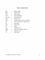
Table of Abbreviations
AD
BOVI
CO2
ECG
E.T. tube
FGF
IASA
I:E
I/O
N20
°2
OR
PEEP
RR
VT
=
=
=
=
=
=
=
=
=
=
=
=
=
=
=
analog to digital
electrocautery
carbon dioxide
electro-cardiogram
endotracheal tube
fresh gas flow
intelligent alarm system in anesthesia
ratio of inspiration to expiration time
input/output
nitrous oxide
oxygen
operating room
positive end expiratory pressure
respiratory rate
tidal volume
An Intelligent Alarm System in Anesthesia
VII
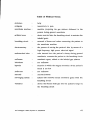
Table of Medical Terms
abdomen
belly
analgesia
insensitivity to pain
anesthesia machine
machine preparing the gas mixture delivered to the
patient during general anesthesia
artificial nose
device inserted into the breathing circuit to moisten the
inhaled gases
breathing circuit
network of hoses and valves connecting the patient to
the anesthesia machine
electrocautery
the process of cutting the patient's skin by means of a
high frequency, high power electrical signal
endotracheal tube
tube inserted into the patient's airway during general
anesthesia, connects the patient to the breathing circuit
enflurane
anesthetic agent, added to the inhaled gas mixture
halothane
see enflurane
hypoxia
situation in which the oxygen saturation of the patient's
blood is too low
isoflurane
see enflurane
narcosis
unconsciousness
scavenging system
system that removes excess anesthetic gases from the
breathing circuit
ventilator
device that forces fresh gas into the patient's lungs via
the breathing circuit
An Intelligent Alarm System in Anesthesia
Vlll
INTRODUCTION
During surgery the patient is under anesthesia: unconscious and insensitive
to pain. The anesthesiologist maintains the patient's vital organ function during
anesthesia.
The clinician gets important information about the patient's status
from several monitors connected to both patient and equipment. However, the
number of monitors increases steadily in today's operating room (OR), making the
situation more and more complex. Each monitor is equipped with its own alarms,
generating a sound or displaying a message whenever a measured quantity exceeds
its user-defined threshold. During a number of situations, many monitors sound
an alarm simultaneously, making it very difficult for the clinician to diagnose the
situation and correct an emerging problem.
A few years ago, the Intelligent Alarms Project was started as a joint
venture between the University of Florida, Gainesville, U.S.A., and the Eindhoven
University of Technology, Eindhoven, the Netherlands, with the intention to
develop a working prototype of an integrated alarm system. This system should
combine several signals in order to come up with intelligent alarm messages
whenever an abnormality is detected during the course of anesthesia.
In 1988,
Van Oostrom [1] implemented a first version that processes three signals measured
in the anesthesia breathing circuit, transforms the signals into symbolic "feature"
data and evaluates and combines these symbolic data using a rule based expert
system.
From this first prototype, a refined system was developed and tested.
The system concentrates on mechanical malfunctions in the breathing circuit.
After an introduction to anesthesia (chapter 1) and current alarm strategies
(chapter 2), the configuration of the final version of this first prototype is
described in chapter 3. The results of extensive testing procedures are given in
chapter 4.
The second goal of this thesis research project is to design and implement
a second prototype Intelligent Alarm System, able to adapt automatically whenever
the clinician changes control settings on the anesthesia machine or ventilator (the
An Intelligcnt Alarm Systcm in Anesthesia
1
first prototype is not able to do this). In chapter 5 the concepts and algorithms
used in this second prototype are described, while in chapter 6 the first test results
of this system are presented.
Funding for the research was provided by Ohmeda Medical Products,
Madison WI, U.S.A., a company manufacturing anesthesia equipment.
An Intelligent Alarm System in Anesthesia
2
CHAPTER 1: A SHORT INTRODUCTION TO ANESTHESIA
Before addressing the issues of monitoring and alarms during anesthetic
procedures a brief introduction to anesthesiology is given in this chapter.
During surgery the patient is in a state of narcosis (unconsciousness), muscle
relaxation and analgesia (insensitivity to pain), usually referred to as general
anesthesia [2). This condition is induced by an anesthesiologist who administers
a combination of intravenous and inhalation drugs to the patient. The task of the
anesthesiologist is to maintain the patient's vital organ function while adequate
levels of anesthesia are sustained.
In order to facilitate this task the patient is
connected to an anesthesia machine via a breathing circuit and to all kinds of
monitoring equipment. In the next paragraphs a short functional description of
the anesthesia system and the most common monitoring equipment is given.
1.1 The Anesthesia System
An important part of the anesthesia system is the anesthesia machine. It
helps the anesthesiologist by preparing a gas mixture with precisely known but
variable composition which is administered to the patient. In the United States
the gas combination most frequently used consists of oxygen (02)' nitrous oxide
(N 20) and an anesthetic agent (halothane, isoflurane, or enflurane).
The
anesthesiologist can control the relative volume of each of these composites. He
delivers the gas mixture to the patient by manually squeezing a "breathing bag" or
by using a mechanical ventilator usually mounted on the anesthesia machine.
The anesthetic system is generally divided into 5 major parts [1):
1. High pressure system,
2. Low pressure system,
3. Breathing circuit,
4. Ventilator system,
5. Scavenging system.
An Intelligent Alarm System in Anesthesia
3
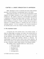
A schematic of the entire anesthesia system is given in figure 1.1.
OXYGEN IN
NITROllS OXIDE IN
I
FWWMETER 1
VENTILATOR
+ SCAVENGING
SYSTEM
EXCESS GAS
OUT
Figure 1.1: Schematic of the anesthesia system. The arrows indicate gas flows.
The 5 parts of the anesthesia system from figure 1.1 can be described as
follows:
1. The high pressure system regulates the gases coming from the hospital
pipeline system (Oz, NzO, and usually air) or, in case of pipeline failure, from
cylinders mounted on the back of the anesthesia machine. The highly pressurized
gases are converted to low pressure by a network of pipes, valves and regulators
inside the anesthesia machine [3] before they enter the low pressure system.
2. The low pressure system contains separate flowmeters that are calibrated
for either 0z, NzO or air. With control knobs the anesthesiologist can adjust the
gas flow for each of the components.
An Intelligent Alarm System in Anesthesia
Upon exiting the flow meters the gas
4
components are mixed and driven through a vaporizer,
In
which a controllable
volume of anesthetic agent is added to the mixture. After passing the vaporizer
the gas mixture leaves the anesthesia machine at the fresh gas outlet and enters
the breathing circuit.
3. The breathing circuit shown in figure 1.1 is the circle breathing circuit,
in which carbon dioxide (C02) is removed from the exhaled gas mixture by a CO2
absorber. Most of the times the CO 2 absorber is placed in between the ventilator
and the fresh gas inlet. In this way exhaled gases can be reused so that as little
gas and anesthetic agent as possible is lost to the scavenging system.
The circle system is the most common breathing circuit used in the United
States today, and is the main focus of our research.
Other hreathing circuits
include the Bain and Mapleson systems [3) in which no rehreathing of anesthetic
gases takes place. These circuits are not considered in our research.
TO VENTllATOR/
SCAVENGING
FRESH GAS IN
~YSTEM
\ ===---=fCo~1
EXPIRATORY
HOSE
INSPIRATORY
~
HOSE
-PIECE
E.T. TUBE
g
PATIENT
}'igure 1.2: Detailed schematic of the circle breathing
circuit. The arrows indicate gas flows.
An Intelligent Alarm System in AneSlhesia
5
A detailed schematic of the circle breathing circuit is given in figure 1.2.
Important components include the inspiratory and expiratory hoses, two unidirectional valves, the CO2 absorber and the endotracheal (E.T.) tube. All these parts
The
together compose a system through which the patient is ventilated.
unidirectional valves (one is placed in the inspiratory, one in the expiratory hose)
accomplish that gas inhalation and gas expiration take place through different
hoses. In this way the expired (02 poor, CO2 rich) gases cannot be reinspired at
the next inhalation without having passed through the CO2 absorber and along the
fresh gas inlet.
The E.T. tube is placed into the patient's airway by the
anesthesiologist at the beginning of general anesthesia. The tube is connected with
a "Y-piece" to the inspiratory and expiratory hoses. At the fresh gas inlet new 02
rich gas from the anesthesia machine is mixed with the gas coming from the CO 2
absorber. This mixture is delivered to the patient [J ,2,3).
4. The mechanical ventilator is the driving force behind the breathing
system.
It is used to move gas into the patient's lungs.
Usually this is ac-
complished by periodically applying a positive pressure to a bellows connected to
the airway, forcing the gas mixture through the inspiratory hose and the E.T. tube
into the patient's lungs. When the lungs are filled to a suitable level, the positive
pressure is removed.
In this way the lungs can empty passively through the
expiratory hose into the ventilator bellows. This process is repeated continuously.
The two types of mechanical ventilators commonly used in the United States
are the constant flow generator and the constant pressure generator [4].
The
constant flow generator delivers, as its name states, a constant but adjustable
inspiratory gas flow to the patient whereas the constant pressure generator
maintains a constant airway pressure during inspiration.
On the ventilator the anesthesiologist can make changes to adjust for type
of operation, demographic patient data or specific patient conditions [1,4].
Adjustments can be made for tidal volume (VT ), respiratory rate (RR) and
inspiratory to expiratory ratio (I:E). VT is the gas volume delivered to the patient
An Intelligent Alarm System in Anesthesia
6
during one breath, RR the number of respirations in one minute and I:E the ratio
of inspiration to expiration time. Depending on the type of ventilator used, the
fourth important setting is either the inspiratory flow (FI' constant flow generator)
or the inspiratory pressure (PI' constant pressure generator).
The anesthesiologist can also switch to a breathing bag with which he can
manually ventilate the patient.
This is often used during emergency or during
critical phases in anesthesia like intubation (entering the E.T. tube at the
beginning) and extubation (taking out the E.T. tube thereby allowing the patient
to breathe by himself after surgery).
5. The scavenging system removes excess gases from the breathing circuit.
At the end of expiration a valve to the scavenging system opens, thereby allowing
gas to leave the circuit. The scavenging system removes the excess gas from the
operating room (OR) to prevent pollution of the clean OR air with anesthetic
gases.
1.2 The Most Important Monitoring Equipment
During surgery a variety of monitors is connected to the patient while other
measuring devices are inserted into the breathing system.
This gives the
anesthesiologist the ability to discover changes in the state of the patient or
malfunctioning equipment as early as possible so that corrective action can be
taken in time.
A standard for minimal monitoring defined by the American
Society of Anesthesiologists (ASA) in 1986 (5) requires that at least the patient's
oxygenation, ventilation, circulation and temperature are monitored continuously.
In most cases the oxygen level of the inspired gas is measured with an 02
analyzer placed in the breathing circuit near the fresh gas inlet.
Oxygenation of blood is usually measured with a pulse oximeter.
This
monitor uses differences in light absorption characteristics between hemoglobin and
oxyhemoglobin to calculate the oxygen saturation of the blood.
An Intelligent Alarm System in Anesthesia
7
The ventilation of the patient is typically measured with a capnograph. This
device monitors the partial pressure of CO2 in the gas mixture. The signal
contains a variety of information about the patient and equipment statuses [6).
Most of the times the CO 2 content of the gas is measured at the Y-piece of the
breathing circuit. Other common monitors that help the anesthesiologist evaluate
the patient's ventilation are an airway pressure monitor (usually placed near the
inspiratory one way valve) and a tidal volume or flow monitor in the expiratory
limb of the breathing circuit [2).
In order to provide the anesthesiologist with some information about the
patient's blood circulation two more variables are measured. The first signal, the
electro-cardiogram (ECG), gives information about the electrical activity of the
heart.
The ECG
patient's chest.
IS
measured with three or more electrodes attached to the
The second variable is the blood pressure.
Blood pressure is
measured continuously, usually noninvasively with an inflatable cuff. Sometimes,
when the anesthesiologist wants to see a real time waveform, blood pressure is
measured invasively with an arterial catheter.
Other variables monitored are temperature (typically measured with a thermocouple or thermistor based sensor) and the degree of muscle relaxation [2).
Despite this abundance of mechanical and electrical devices available to
help the anesthesiologist, his own eyes, ears and sense of feeling are still the most
important "monitors" available [2,7).
Thus, the alarm system described in this
thesis should be considered as an attempt to provide the anesthesiologist with
valuable extra information when time, an extremely important factor in emergency
situations, is limited. It is certainly not an attempt to replace the anesthesiologist.
An Intelligent Alarm System in Anesthesia
8
CHAPTER 2: ALARM STRATEGIES IN ANESTHESIA
Before describing our approach to design an "intelligent" integrated alarm
system we review the work that already has been done in this area. In the next
paragraphs an overview of the literature of the last decennium about alarms and
integrated alarm systems in anesthesia is presented. A brief introduction to our
strategy is given at the end of this chapter.
2.1 Current State of Alarm Technology
The purpose of alarms during anesthesia is to get the clinician's attention
whenever a potential hazard is detected regarding the patient or the anesthesia
equipment. For this purpose the monitors used during anesthesia are equipped
with their own alarm limits. Currently, the available alarm technology relies on
the "threshold-check". For each variable measured by a particular monitor, the
clinician has to define what he considers the "normal" band before the start of
anesthesia. This means that an alarm message will be generated when a variable
exceeds either its upper or its lower limit.
Usually the alarm is a tone of a
certain frequency, sometimes combined with a text message on the monitor's
display.
When, for example, one only considers a blood pressure monitor, this
strategy will certainly be appropriate. An alarm message is generated whenever
e.g. the systolic blood pressure exceeds its set upper limit. In this case, the audio
alarm will be specific and easy to interpret for the anesthesiologist.
However, the monitoring situation in today's operating room (OR) is more
complicated.
In paragraph 1.2 the minimal array of monitors used during
anesthesia was briefly described.
independent of all the others.
Each of these monitors has its own alarms,
Considering the fact that an alarm is usually
accompanied by all sorts of other alarms some of the problems of the current
strategy already become clear.
An Intelligent Alarm System in Anesthesia
9
In an emergency situation, when many measured variables can exceed their
set limits, the clinician's first reaction will be to silence the abundance of audio
alarms.
In these situations it is often very difficult for the anesthesiologist to
diagnose the problem because the alarms are not specific and do not point out
possible causes. Other problems that can be identified are (2):
- It becomes increasingly impractical for the clinician to set all the
thresholds for all the variables manually.
- The alarms do not give an early indication when the situation
tS
slow-
ly deteriorating without variables exceeding thresholds.
- There is no priority scheme for alarms coming from different monitors.
All triggered alarms will ring the bell simultaneously.
- It is very difficult for a single variable monitor to detect the difference
between a potentially hazardous situation and a threshold crossing triggered
by a motion or other interference. This is the well-known artifact detection
problem [9].
For all these reasons research efforts in the last few years have focused on
how to generate helpful and specific alarms. Recent publications point out that
multivariable analysis and integration is needed in order to come to more
"intelligent" alarm messages. A brief survey of recently proposed alarm strategies,
their problems, and examples of implemented and tested (prototype) systems is
presented in the next paragraph.
2.2 Survey of Modern Alarm Strategies
The first attempt to compile a survey of research activities regarding alarm
strategies and implementations other than the threshold-check was performed by
Gravenstein et al. in 1987[8]. In this survey, Philip, Fukui, and Beneken propose
three different approaches to sophisticated and useful alarms in patient monitoring.
An Intelligent Alarm System in Ancsthcsia
10
Philip [10] defines the patient's state as the set of variables that must be
known to manage the patient.
In a first approximation he looks at only two
possible patient states: the "correct state" and the "incorrect state".
For the
detection of abnormalities, a change detection scheme is used for all the monitored
variables.
Whenever a change is detected the patient will enter the "incorrect
state". At the same time the dimension of the state vector changes from 1 (fault
or no fault) to 4 (four different fault categories are distinguished) and an alarm
message is generated. The algorithm determines whether the abnormality occurred
in circulation, anesthesia, respiration, or metabolism (the 4 subsystems). The state
dimension increases with growing severity of the situation.
Circulation, for
example, can be subdivided into medium (blood), conduits (blood vessels), and
pump (heart).
The advantage of this system is that the clinician only needs to
observe a minimum number of variables during stable situations. A disadvantage,
however, is the fact that the complexity of the system increases rapidly with a
growing number of states.
Fukui [11] uses an approach borrowed from Artificial Intelligence (AI). A
number of patient variables, including blood pressure, ECG, and temperature are
continuously sampled and translated into one of three symbolic values.
By
comparing them to certain predefined thresholds each variable gets assigned a
value "high", "low" or "just right".
Pattern recognition techniques are used to
identify abnormalities in the patient system. Fukui has implemented this algorithm
together with a graphical display on which, among others, the blood pressure trend
is displayed.
Furthermore a sad or happy cartoon face gives an immediate and
easy to interpret indication about the patient's condition.
Beneken et al. [12] use systems engineering principles in their approach.
They consider the measured output quantities as a function of input variables,
actual outputs, a noise component, and time. They use a patient model together
with a library of fault models (each possible fault will have a certain unique effect
on the measured output quantities).
The algorithm reduces each measured
variable to a three-digit number, which indicates the static, dynamic and stochastic
An Intelligent Alarm System in Anesthesia
11
properties of the respective variable. Each fault model is stored as a set of these
three-digit numbers. At any moment the algorithm can decide whether the patient
is OK, and, if not, which is the most probable "fault".
Recently Philip (13) and Fukui (14) published an update on their ongoing
research regarding their alarm algorithms mentioned before. Also, Beneken et al.
(15) looked at alarms and their limits, on which issue we will come back in later
chapters.
Apart from the Fukui system very few implemented integrated alarm
systems are described in the literature.
Most of them are outlined in the next
paragraph.
2.2.1 Overview of Implemented Integrated Systems
One of the best structured alarm systems that is already commercially
available is implemented in the Narkomed II anesthesia machine manufactured by
North American Drager. It is described by Schreiber et al. (16). The system uses
several sensors distributed over anesthesia machine, breathing circuit and patient,
together with a centralized display.
In this way the time the clinician needs to
identify and correct a problem is minimized. A priority scheme is used to divide
the alarm messages into warning, caution and advisory messages. Although the
alarms are still threshold-based and no multivariable analysis is performed this is
a first step toward smarter alarm systems.
Another implementation, although only on a prototype basis, is the Data
Acquisition and Display System (DADS), developed at the Eindhoven University
of Technology and described by Meijler (17).
This system incorporates a
centralized display, automatic record keeping capabilities, and a threshold and
trend detection scheme. The problem of many superfluous alarms is not solved
however, basically because no multivariable analysis is performed.
A ventilator alarm system for use at the NASA Space Station, developed
at the University of Utah by Brunner et al. (18), already incorporates some
An Intelligent Alarm System in Anesthesia
12
"intelligence". A large number of transducers is placed at different sites of the
breathing circuit and ventilator in order to identify several malfunctions during
mechanical ventilation. Specific alarm messages can be generated by combining
the signals coming from the different monitors via "if-then-else" rules. Early results
indicate 98% correct identification of mechanical faults.
The large number of
sensors prevents the system from being commercially attractive at this moment.
Furthermore, an implementation of a "breathing gas interruption" monitor
for use in the breathing circuit during mechanical ventilation is described by
McEwen et al. [19,20]. This monitor can detect different hazardous situations in
the breathing circuit by measuring only the pressure waveform. The waveform is
compared to a learned "correct" waveform and when differences are detected an
alarm message is generated.
The alarms are not specific however, and no
multisignal analysis is performed.
Other papers present only general conceptional or philosophical descriptions
of system integration and use of computers for alarms in anesthesia [21,22,23].
2.3 The Gainesville Approach
As demonstrated in the beginning of this chapter there is a clear need for
a system that is able to detect and identify abnormalities in the patient-machine
combination during anesthesia. This has to be done in real time, by combining
and evaluating several signals, derived variables and other patient data.
The
Intelligent Alarms System in Anesthesia (IASA) project started a few years ago at
the University of Florida in Gainesville and the Eindhoven University of
Technology with the intention to develop a working prototype of such a system.
In this paragraph the general method is explained briefly before an extensive
description of the first prototype configuration is presented in the next chapter.
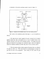
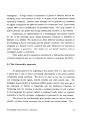
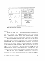
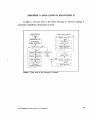
The process the anesthesiologist goes through when he tries to locate and
identify a problem during anesthesia can be divided into several phases. This
An Intelligent Alarm System in Anesthesia
13
subsequent checking of different parts of the patient-equipment combination is
schematically pictured in figure 2.1.
LEVEL 1
!SITUATJON STABLE?
1
1
LEVEL 2
PATIENT
OK?
EQUIPMENT
OK?
1
LEVEL 3
GAS
SUPPLY
OK?
---
---:---1-
1
PCAVEN- _ VENTIGING
LATOR
OK?
OK?
------ ; - - - -
.
~
BREA
TIIIN G
CIRCUIT
OK?
I'IWTOTYPE I
PROTOTYPE II •
Figure 2.1: Schematic of the decision process of the anesthesiologist.
The final goal is to design a system that can give intelligent messages about
abnormalities occurring in the patient as well as in the equipment. Because of the
enormous complexity of especially the patient "system" (many factors influence the
situation of the patient during anesthesia) we choose to start cautiously. The first
prototype incorporates an alarm scheme that detects mechanical malfunctions in
the breathing circuit during mechanical ventilation.
This is performed by
measuring and combining a carefully chosen set of signals in or close to the circle
breathing circuit.
An Intelligent Alarm System in Anesthesia
14
The goal for the second version is to incorporate ventilator related
malfunctions in the alarm system.
The target parts of prototypes I and " are
illustrated in figure 2.1. The design and testing of these first two prototypes are
described in the next chapters.
Once proven, these designs will be the platform to incorporate other patient
variables and signals to come to a truly integrated alarm scheme.
An Intelligent Alarm System in Anesthesia
15
CHAPTER 3: IASA: THE FIRST PROTOTYPE
The goal for the first prototype is the automated detection of the
malfunctions that can occur in the circle breathing circuit during mechanical
ventilation in the operating room (OR). In this chapter a detailed description of
the software and hardware that composes this prototype alarm system is presented.
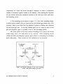
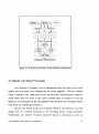
3.1 The Data Flow through the System
Before we look in more detail into the configuration of the system, a
schematic of the data acquisition, signal processing, feature extraction and rule
evaluation performed before an alarm message appears on the screen is pictured
in figure 3.1. This design was proposed and first implemented by Van Oostrom
[1] although the implementation of the signal processing part was already
performed earlier by Bastings [24].
The system first processes three real time signals measured in the breathing
circle: partial pressure of carbon dioxide (C0 2) at the Y-piece, airway pressure
close to the inspiratory valve and airway flow through the expiratory valve. The
signals are transformed into symbolic "feature" values and subsequently fed into a
real time expert system at the end of each breath period (later on in this chapter
we will define "breath period" and "feature").
Signals and signal features are
chosen so that each fault that can occur in the breathing circuit will be reflected
as a change in the set of symbolic data.
The expert system evaluates and
combines the feature data derived from the different signals, looks for changes in
this data set, reaches a conclusion about the status of the breathing circle ("OK"
or "ALARM"), and gives an "intelligent" indication about mechanical malfunctions
that have occurred, together with their most probable site.
The signal processing, feature extraction and expert system approaches are
described in detail in the following paragraphs.
An Intelligent Alarm System in Anesthesia
16
SIGNAL
P~OCESSING ~
FEATURE
_/
. :- _~~~~CTc:N-~ ~-~ 1
SYWBOIJCj
[
s¥unOl.H:
SIGNAL
SII;NAI.
FUTIlHES
nATURES
~-l--=.l·
C
--RUu.:
-I ..
~
~
HASED
EXPERT SYSTEM
INTELUGENT ALARM MESSAGES
Figure 3.1: Data now in prototype I of the Intelligent Alarm System.
3.2 Signals and Signal Processing
Van Oostrom (1) defines a list of malfunctions that can occur in the circle
system and thus need to be detected by the alarm program. This list includes
leaks at different sites, obstruction of the various hoses, disconnections, unidirectional valves that are stuck in the "open" position (due to moisture in the gas
mixture), and exhaustion of the CO2 absorber (the absorber can no longer remove
CO2 from the exhaled gas mixture).
Because the system needs to be clinically usable, it was decided to use only
signals that are routinely measured in the breathing circuit during anesthesia.
Furthermore, the number of sensors should be kept to a minimum in order not
An Intelligent Alarm System in Anesthesia
17
to make the system more complicated than necessary. The set of signals chosen
for prototype I consists, as mentioned in § 3.1, of the partial CO 2 pressure
measured at the Y-piece of the breathing circuit, the airway pressure measured
downstream (at the patient side) of the inspiratory unidirectional valve and the
airway flow measured upstream (at the patient side) of the expiratory unidirectional valve (see also figure 1.2).
This is the most common way of placing the
sensors in today's clinical practice.
3.2.1 From Monitors to Sampled Signal Waveforms
Standard monitors manufactured by Ohmeda, Madison, WI, are used to
obtain the waveforms. The Ohmeda 5200 CO 2 Monitor and the Ohmeda 5500
Airway Pressure Monitor provide analog outputs for the respective signals. The
analog signals are fed to an analog to digital (AD) board inside an IBM AT
compatible computer. With the AD-board sampled versions of the signals are
produced.
The samples serve as input to the signal processing software.
Van
Oostrom [1] describes how a real time flow signal is created by counting pulses
generated by the Ohmeda 5410 Volume Monitor. Tests showed that a sampling
frequency of 20 Hz is enough to calculate all signal features even at the highest
respiratory rates (sometimes an RR of up to 30 breaths/min is used in pediatric
or neonatal anesthesia).
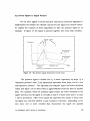
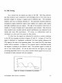
A typical example of the three real time waveforms in a no-malfunction
situation during mechanical ventilation of an adult patient is given in figure 3.2.
During patient inspiration the pressure signal will go up linearly due to the
constant flow the ventilator forces into the lungs.
There is no flow
In
the
expiratory limb of the circuit during inspiration. When the positive pressure from
the ventilator is removed, the expiratory valve opens and the flow through the
expiratory limb suddenly starts. This marks the start of patient expiration (see
figure 3.2). At this moment CO 2 rich gas from the lungs starts passing the CO 2
sensor.
An Intelligent Alarm System in Anesthesia
18
/
Delay lime
IdChClC
:CAJ
a
0":10
:
'61018
,
Time [!lee]
10
10
ao
a6
Time [gee]
~[mk ~ ~
\
Figure 3.2:
"
Time [_ee]
Start of patient expiration
Example of 3 real time waveforms in an adult
patient.
Since the lungs empty passively the flow and pressure signals show an
exponential down slope (much like the discharging of a capacitor via a resistance),
whereas the CO 2 signal increases quickly to an end expiratory "plateau" value.
This value is approximately equal to the alveolar CO2 concentration. With
another inspiration, the patient will inhale fresh gas without CO2 and thus the
signal will go down to zero.
Due to the fact that the CO 2 monitor removes gas from the Y -piece via
a sampling line, a delay is observed in this signal compared to the flow and
pressure recordings.
As can be seen from figure 3.2, gas transport from the
Y-piece to the monitor takes approximately 2.5 seconds.
An Intelligent Alarm System in Anesthesia
19
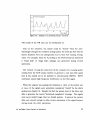
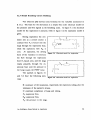
3.2.2 From Signals to Signal Features
For all three signals a breath detection and feature extraction algorithm is
implemented that divides one (breath-) period of each signal into several "states".
To explain the concepts of these algorithms we take the pressure signal as an
example. In figure 3.3 the signal is pictured together with some help variables.
Pressure
2 : 3:
j Inllpiration
4
Elpiration lime
time
••- -_ _ nrl!'ftlh time
Time
------oi
Figure 3.3: The pressure signal divided into several states.
The pressure signal is divided into 1) a linear inspiratory up slope, 2) a
"maximum pressure" state, 3) an exponential expiratory down slope, and 4) a low
end-expiratory "plateau". The algorithm uses adaptive upper and lower threshold
values (see figure 3.3) to detect when a signal switches from one state to another
[24]. For example, when the pressure signal crosses the lower threshold in the
upper direction and the signal is currently in state 4 a switch from state 4 to state
1 will be performed. After every sample the algorithm first checks in which state
the signal was, and then whether a state transition is detected. Depending on the
new state, one or more variables that characterize the signal are updated
An Intelligent Alarm System in Ancsthesia
20
thereafter. For the pressure signal, the variable to be updated in state 1 is the
pressure derivative or slope value (P slope)'
In state 2 this is the maximum
pressure (P max)' whereas the time constant of the down stroke (Tp) has to be
estimated in state 3.
pressure (P min)'
Finally, in state 4 the algorithm looks for the minimum
Other variables have to do with the timing and include
inspiration time, expiration time and breath time. The theoretical value of these
variables is indicated in figure 3.3. The inspiration time is estimated by adding the
time periods of state 1 and 2, the estimated expiration time is the sum of the state
3 and state 4 time, breath time is the sum of both.
For the pressure signal, the transition from state 2 to state 3 is considered
the start of a new breath period. For the flow signal a breath period starts with
the detection of the "jump" in expiratory flow which ends the "zero-flow-period",
whereas a new breath period for the COz signal starts at the beginning of the up
slope (see figure 3.2). This means that breath detection is performed at the start
of patient expiration for every signal.
Thus, as soon as a new breath has been detected on every signal a
complete set of numerical "features" representing one breath period of all signals
is available. These features are used in the fault detection scheme. For the COz
signal the features include the inspired COz level (P iCOZ )' the end-tidal COz level
(PetCOZ)' the values of the (linear) expiratory up slope and inspiratory down slope
and the "plateau" time. The flow features are, next to timing variables, maximum
flow (Fmax)' minimum flow (Fmin)' the time constant of the expiratory down stroke
(T F) and tidal volume (VT). The latter variable is calculated by integrating the
positive part of the flow curve during one breath period.
Van Oostrom (1) describes the algorithms used in the initial implementation
for calculating m'!Ximum and minimum values, slopes and time constants.
However, the time constant and slope algorithms have been updated to speed up
the signal processing.
The derivative of the pressure waveform is updated and filtered after each
incoming sample.
The value of the filtered derivative at the moment the
An Intelligent Alarm System in Anesthesia
21
algorithm detects a transition from state 1 to state 2 (see figure 3.3) equals Ps1ope '
The results of this method turned out to be reliable and stable and were
practically the same as the slope values acquired with the old least squares
algorithm, whereas the speed of the new method is considerably higher.
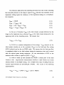
In the following the technique used for estimating the time constant of the
exponential down stroke in the pressure and flow signals is explained.
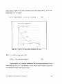
3.2.2.1 How to Estimate the Time Constant
We assume that the analog pressure signal yet) enters state 3 (see figure
3.3) at t = 0 sec. and exits this state at t = Tend (for the flow signal a similar
state is implemented). So, the following formula is valid:
yet) = Ystart x exp(-trrc) for O<t<Tend
(3.1 )
The time constant Tc of this signal has to be estimated from z(k), a
sampled version of yet):
z(k)
=
y(kTs) for k
=
0, I, 2, ... , (Tendrrs)
(3.2)
In (3.2) Ts is the known sample time, which is equal to (1IFs) with Fs the
sample frequency. In our case Fs
= 20
Hz. In figure 3.4 a graph of yet) and its
samples y(kTs) is pictured.
From (3.1) and (3.2) we see that when two consecutive samples z(k) and
z(k+ 1) are divided the result is a constant, independent of k:
z(k+1)/z(k) = exp(-Tsrrc)
(3.3)
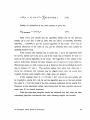
Tests on pressure and flow signals recorded in the OR showed that Tc
almost always lays in between 0.3 and 1.5 sec. In our algorithm we take an extra
An Intelligent Alarm System in Anesthesia
22
safety margin of 50% of the lower boundary value and assume that Te > 0.15 sec.
Filling this in in (3.3) gives:
0.7 < ( z(k+ l)/z(k) ) < 1, for Te > 0.15 sec.
r - z(O)
:;;;:
(3.4)
Yi!ltarl
.......... /=..z(1)
,
,,,
,,
~ __
:
z(2)
····:1,
.. : ........ j....
:
:
'
!
_t
Figure 3.4: Graph of an exponentially decreasing time scries.
With Ts = (ifFs) we get from (3.3):
(lITe)
=
-Fs x In( z(k+ I)/z(k) )
(3.5)
Suppose there are n samples available in the decreasing exponential curve,
called z(O) up to z(n-I). An estimation of the inverse time constant is given by
the following average value (from (3.5»:
An Intelligent Alarm Systcm in Anesthesia
23
n-2
!, InC z(i+l)/z(i) )
i~O
(3.6)
Finally, an estimation of the time constant is given by:
[Tel estimated
= 1/< lfTc>
(3.7)
After every new sample z(i) the algorithm divides z(i) by the previous
sample z(i-l) and uses a look-up table with the values of In(0.700), In(0.701),
In(0.702), ... , In(0.999) to get the natural logarithm of the result.
This wayan
updated estimation of the value of 1fTc can be obtained after each sample by
updating formula (3.6).
If by accident (for example due to noise) z(i) > z(i-l) the algorithm waits
for z(i+ 1), divides z(i+ 1) by z(i-l), and if the result lays in between 0.7 and 1 it
looks up the natural logarithm of the result. The logarithm is then added to the
sum in (3.6) twice, because the time between z(i+l) and z(i-l) is two times Ts.
This process goes on until a value z(i+j) is found so that z(i+j) divided by z(i-1)
lays in between 0.7 and 1. This method implies that, when very often z(i) >
z(i-l), the calculated time constant may be slightly lower than the actual time
constant because some samples with a high value are skipped.
If (for example when Tc < 0.14) z(i) < (0.7 x z(i-l» the new sample will
be rounded to exactly (0.7 x z(i-1» and the algorithm goes on to the next sample.
So, when Tc < 0.14 the result of the time constant estimation will be exactly 0.14.
However, as was mentioned earlier, tests showed that the time constant was never
lower than 0.3 in clinical situations.
With this algorithm adequate results are obtained very fast, since the time
consuming logarithm calculations after each incoming sample are avoided.
An
Intelligent Alarm System in Anesthesia
24
3.2.3 Signal Validation
Slope values and time constants are only considered valid if they are based
on a minimum number of samples in the respective curve parts. At this moment,
a minimum of six samples is required for both features to be valid.
Furthermore, the breath time is stored for every signal after breath
detection. The signal processing waits a maximum of 120% of this previous breath
time for the next breath detection. If no new breath is detected within this time
span the signal is declared invalid and a time-out flag is set.
When a signal is
invalid all of its features are considered invalid for that particular breath period.
By setting a time-out flag the system is prevented from waiting forever until a
breath is detected.
When all the numerical feature values are available (after breath detection
or time-out on all three signals) an extra cross check is performed to test whether
the timing variables of the signals are in accordance with each other. For all the
valid signals, the inspiration, expiration and breath times are compared.
If the
data from one signal vary more than 20% from the variables coming from the
other two, the signal is declared invalid.
In this way the redundancy that is
available is used as good as possible for signal validation.
3.3 Symbolic Data
Since the expert system needs symbolic data rather than numerical data as
its input the calculated numerical features are translated into symbolic format.
Features that are declared invalid (see § 3.2.3) get the symbolic value 'NV' (Not
Valid). As Van Oostrom (1] describes the valid feature values are compared to
a value that is considered -to be "normal" for that feature in a no-malfunction
situation. This reference value will be called the "feature baseline" from now on.
At the beginning of an operation, the anesthesiologist currently has to push
a "RESET BASELINES"-hutton when the signals are stationary and he accepts
An Intelligent Alarm System in Anesthesia
25
them as normal. At that moment all baselines will be reset to the current running
average of the feature value, thereby assuming that no malfunction is present.
Resetting the baselines is necessary because the set of initial (default)
baselines (based on an average adult patient) is often inadequate. The "normal"
values depend heavily on the ventilator settings used, demographic patient data
(age, weight, sex) and type of operation.
Tidal volume, for example, can vary
from 100 ml for neonatals to over 1 liter for young athletes.
For every feature a particular low and high threshold is defined, with the
baseline of that feature as a reference, in a look-up table.
The zone between
upper and lower threshold is called the normal band for that feature.
For
example, assume a default baseline value for the maximum flow of 600 ml/sec.
When the low and high thresholds for the maximum flow feature are set to 30%
and 20% respectively the normal zone will be the band between 420 and 720
ml!sec.
Also, for each feature a minimum value is defined. When the baseline is
below this minimum the thresholds are absolute rather than relative to the baseline
to prevent the normal band from becoming too small.
This is particularly
necessary for features that have a natural baseline close to zero, like minimum
flow or inspired CO 2,
At the end of each breath period, each valid feature gets assigned a
symbolic value.
These values range from 'UC' (UnChanged) when the feature
value lays within the normal band, 'UP' (Up) when the feature value lays above
the upper threshold, to 'ON' (Down) when the feature value is smaller than the
lower threshold. The set of symbolic values (,UP', 'ON', 'UC', 'NV') serves as
input to the expert system after each breath period.
3.4 The Real Time Expert System Approach
The goal for the first prototype of the Intelligent Alarms System is to
provide the user with a conclusion about the integrity of the anesthesia breathing
An Intelligent Alarm System in Anesthesia
26
circle after every breath period.
Van Oostrom [1] explains the reasons for
choosing the SIMPLEXYS Expert System Language, developed at the Eindhoven
University of Technology, Eindhoven, The Netherlands by Blom [25,26] as a tool
for our implementation. The main advantage of SIMPLEXYS is the fact that it
provides "hooks" to a high level programming language (currently, SIMPLEXYS
versions for Pascal and for C are available) and therefore data acquisition and
graphical user interface routines can easily be interfaced with the expert system
body.
After compilation, this provides a fast and efficient program.
The
SIMPLEXYS language was especially designed for real time expert system
applications.
The expert system body consists of a set of rules, that contain the expert
knowledge in the system. Starting with one or more "root" rules the complete rule
set (or a part of the rule set) is evaluated after every breath. Every rule to be
evaluated gets assigned a value 'TR' (True ), 'FA' (False) or 'PO' (Possible).
Depending on the result other rules may be triggered and evaluated as a
consequence.
For every malfunction in the breathing circle to be detected, a rule
describes how different feature values change when this malfunction occurs. In
order to make every rule unique, some features that remain unchanged CUC) can
also be added to the rule. Van Oostrom [1] gives the complete set of rules in the
prototype I system. This preliminary rule set was the result of extensive research
and discussions with anesthesiologists (the "experts").
In order to make clear how the rule evaluation concept works a simplified
version of some of the SIMPLEXYS rules is given in table 3.t.
Every SIMPLEXYS run starts with looking at one or more rules of the
"STATE" type. Each rule of this type has one or more "GOALS". The rules to
be evaluated next are the GOALS belonging to the STATE rule(s) with value 'TR'
(True). So, in table 3.1 the rule that checks whether there is no malfunction in
the breathing circle (BREATHING_SYSTEM_OK) is always evaluated first. This
rule is composed of different "subrules" like the rules that test for incompetent
An Intelligent Alarm System in Anesthesia
27
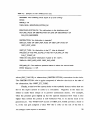
Table 3.1: Example of some SIMPLEXYS rules.
RUNNING: 'The breathing circutt expert is up and running'
STATE
INITIALLV TR
THEN GOAL: BREATHING_SVSTEM_OK
BREATHING_SVSTEM_OK: 'No maijunctions in the breathing circle'
NOT (INC_VALVE OR OBSTRUCTION OR LEAK OR DISCONNECT OR
EXH_C02_ABSORBER)
OBSTRUCTION: 'An obstruction is detected'
OBST_ET_TUBE OR OBST_INSP_HOSE OR OBST_EXP_HOSE OR
OBST_VENT_HOSE
OBST_ET_TUBE: 'An obstruction in the E.T. tube is detected'
PRS_MAX_UP AND PRS_SLOPE_UP AND NOT FLW_MAX_UP AND
FLW_T_CONST_UP
THEN DO wrtte_alarm( 'Obstruction V-piece or E.T. tube' );
THEN FA: OBST_INSP_HOSE, OBST_EXP_HOSE
PRS_MAX_UP: 'The maximum pressure feature is above the normal band'
BTEST (Maxpres = = UP)
valves (INC_VALVE) or obstructions (OBSTRUCfION) somewhere in the circle.
The OBSTRUCfION rule is again composed of subrules that look at the site of
the obstruction, like OBST_ET_TUBE.
Finally, at this level the system looks at the symbolic feature values that are
fed to the expert system to come to a conclusion.
Negatives in the rules are
added to make them unique or to prevent unnecessary alarms.
For example,
when the pressure goes slightly up but the expired maximum flow value is also
higher than normal the patient is still ventilated well, so no alarms need to be
generated yet. The "THEN DO" section of OBST_ET_TUBE provides a hook to
C, if the rule gets assigned a value 'TR' the C code on the rest of the line is
An Intelligent Alarm System in Anesthesia
28
executed. In this case this means that an alarm message is put on the screen.
The rules after ''THEN FA:" are immediately set to 'FA' without evaluation. The
word "BTEST" provides a second hook to C; the C code on the remainder of the
line is executed and the rule is set to the result of this boolean test. So, the rule
PRS_MAX_UP will get the value 'TR' when the C-variable Maxpres (one of the
symbolic features) has a value UP.
This means that the maximum pressure
feature is higher than the upper boundary of the "normal zone" (see § 3.3).
In the same way the whole rule base is constructed, as can be seen from
table 3.1 this setup is much like a tree structure. In the real implementation an
alarm message is only put on the screen when the same alarm has been triggered
during two consecutive runs.
When an alarm is detected for the first time a
general "CAUTION" message is generated.
This is a protection against false
alarms due to motion artifacts of the patient or other external disturbances.
3.5 Software Upgrades
Compared to the preliminary prototype I system that Van Oostrom [l]
describes some important changes have been implemented before testing the
prototype. Some of them have already been mentioned, like the new algorithms
for slope and time constant estimation, the use of an AD-board to sample the
pressure and CO2 waveforms (§ 3.2) and the possibility to set the threshold values
for every feature separately instead of using a general margin of ± 20% (§ 3.3).
Other important changes are mentioned below:
- The flow, pressure and CO 2 signal processing is done using fixed point
rather than floating point calculation where possible, in order to increase
program speed.
An Intelligent Alarm System in Anesthesia
29
- A new C version of SIMPLEXYS has become available. Since the signal
processing as well as the feature extraction software was already written in
C the Pascal routines in the expert system body were translated into C.
- The use of MultiOos-Plus as a multitasking extension to the MS-OOS
operating system caused a lot of overhead because lots of data had to be
sent from one task to another and back. Therefore we choose to pause the
signal processing during the feature extraction and expert system evaluation
that is performed once a breath. The incoming samples are stored in a
buffer during this short period since the three different programs (signal
processing, feature extraction, rule evaluation) do not run concurrently
anymore. Because all the functional parts are now in the same program
all pertinent data is automatically accessible for all routines. Since the C
version of SIMPLEXYS is able to evaluate approximately 2000 rules per
second, and the prototype I system contains about 60 rules, the "pause"
period is very short and provides no problems for the data acquisition.
- The one-program approach also overcomes the major drawback imposed
by MultiOos-Plus: no support for high resolution graphics. Thus, the real
time graphs of the CO2, pressure and flow waveforms can be presented on
the same screen as the alarm messages now. The raw samples do not have
to be sent to a second PC anymore, the whole system is implemented on
one IBM AT compatible computer.
- Oataiogging capabilities for storing the raw flow, pressure and CO2 data
on hard disk are implemented.
- The rule set is extended with rules that perform extra signal validation
checks before the malfunction detection starts.
An Intelligent Alarm System in Anesthesia
30
CHAPTER 4: TESTING PROTOTYPE I
The system described in chapter 3 has been tested in a clinical environment
as well as on an anesthesia simulator. The protocol and the results of these tests
are presented in the next sections. At the end of the chapter the limitations of
Prototype I and the improvements to be made in a second prototype system are
summarized.
4.1 Simulator Testing
Before going into the operating room (OR) with the system its performance
was tested on the Gainesville Anesthesia Simulator, developed by Good et al. at
the University of Florida, Gainesville, U.S.A. [27]. The simulator consists of an
Ohmeda Modulus II Anesthesia Machine together with an Ohmeda 7800 series
ventilator and the standard monitoring equipment used in the OR.
Using a
standard breathing circuit and endotracheal (E.T.) tube a mechanical lung is
Carbon dioxide (C0 2) is fed to the lung to simulate the CO2
production of the patient. The signals we are interested in, airway pressure in the
ventilated.
inspiratory hose, airway flow through the expiratory hose, and partial CO 2 pressure
at the Y-piece, are obtained with exactly the same monitors as they would be in
the OR.
A number of sensors and actuators makes it possible to introduce
mechanical malfunctions in the breathing circuit or anesthesia machine.
These
include a stuck inspiratory or expiratory valve, an exhausted CO2 absorber and
leaks at different sites. By manipulating circulation-related variables and signals,
like the oxygen (02) saturation of the blood, the electro-cardiogram (ECG), and
the blood pressure, also patient-related mishaps like hypoxia (the 02 saturation of
the blood is too low) and deep or light anesthesia can be simulated. Since blood
circulation is not really present in the simulator these signals are generated by
software rather than physically measured.
An Intelligent Alarm System in Anesthesia
31
~'-'=~~~=+==;----;:=._
Inspiratory
valve
Mechanical
lunC
d _
Fresh gas now
(from Modulus II)
Ohmeda 7610
ventilator
Expiratory valve
To scavenging
CO, cylinder
system
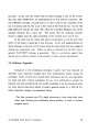
Figure 4.1: Schematic of the test setup with the Gainesville Anesthesia Simulator. The
dashed lines represent electrical signals.
The original purpose of the simulator was to teach anesthesiologists how to
react on rare catastrophic events during anesthesia.
With the simulator the
clinician can practice his reactions to mishaps, and even make mistakes without the
stress of exposing a real patient to a life-threatening condition.
Since the
malfunctions we would want to detect never can be introduced during real
anesthesia, the simulator is the ideal testbench for the Intelligent Alarm System.
The simulator setup and the locations of the sensors used by our system are
schematically pictured in figure 4.1 1.
1 Figure 4.1 is based partly on a drawing of the anesthesia system by 1.S. Gravenstein, MD.
An Intelligent Alarm System in Anesthesia
32
4.1.1 Test Protocol and Results
Using 4 different combinations of ventilator- and fresh gas flow (FGF)
settings, a number of malfunctions was introduced (one at a time).
During a
maximum of 30 seconds or 5 breath periods, whichever came first, the alarm
system was expected to detect a malfunction and generate the correct alarm
message. After that period the system was brought back into the "no-malfunction"
state, and subsequently the next critical event was simulated.
Whenever settings were changed we waited until the system had adapted
to the new signals (this usually takes about 5 or 6 breath periods) and then reset
the feature baselines to their new running average value (see § 3.3). This was
necessary in order to avoid false alarms or missed detections due to the fact that
the baselines were not adequate for the setting combination.
The different combinations of ventilator- and FGF settings are given in
table 4.1. The compliance of the mechanical lung was set to 0.1 I/cmH 20, which
resembles a normal lung compliance value of an adult patient.
The malfunctions introduced by the simulator were: incompetent expiratory
valve, incompetent inspiratory valve, exhausted CO2 absorber, disconnect of the
ventilator hose, CO 2 canister leak, and a leak in the E.T. tube cuff. Manually
introduced were: leaks in different hoses, obstructions of different hoses and
disconnections of hoses other than the ventilator hose.
Table 4.1: Selling combinations used during the tests at the simulator.
Setting DO.
VT (ml)
RR (breaths/miD)
I:E
FGF (I/miD)
1
500
12
1:2
6
2
500
12
1:2
3
3
750
6
1:2
6
4
750
6
1:2
3
An Intelligent Alarm System in Anesthesia
33
Leaks of two different sizes were introduced in the various hoses by
connecting an open tube with a length of 7.5 cm and a diameter of either 1.5 mm
(small leak) or 3 mm (large leak) to the system at the respective locations.
Obstructions were simulated by pinching the hoses.
For setting combination 1 the critical events were repeated 4 times to test
the consistency of the system. The results of all the tests are given in the matrix
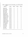
in table 4.2. In this table, two different locations for leaks in the expiratory hose
can be distinguished. Leak 1 was introduced upstream (at the lung side) of the
flow sensor connection, while leak 2 was inserted downstream of the flow sensor.
In the matrix an 'X' indicates that the correct (or best available) alarm message
was generated within the 30 seconds time span, an 'N' means that no alarm was
triggered at all, and an 'F' means that only false alarm messages were generated.
When more alarm messages appeared indicating the system detected more than
one possible malfunction, but the correct message was one of them, the reaction
of the system was still considered correct.
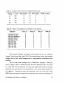
From table 4.2 we see that from the total of 189 events simulated, 167 were
detected correctly, while 20 were not detected and 2 false alarms were recorded.
This means that 88% of the mishaps was detected correctly within 30 seconds.
The two false alarms were an "incompetent inspiratory valve" message, at a small
and at a large leak in the E.T. tube.
To explain the false alarms, the essential parts of the rules for incompetent
valve, large leak, and small leak are given in table 4.3.
When leaks were
introduced at the E.T. tube we observed that the CO 2 down stroke sometimes
went down. In that case, the only difference between a small leak and an
incompetent valve is the maximum flow feature. The difference between a large
leak and a stuck inspiratory valve is the fact that the pressure should go down in
case of a large leak and remain unchanged during a stuck valve.
Since the
maximum pressure did not change the false alarms were generated. This problem
was solved after the test procedure by changing the rules so that, when the
pressure is not going down during a leak in the E.T. tube, two "possible
An Intelligent Alarm System in Anesthesia
34
Table 4.2:
Matrix with test results of IASA prototype I on the Gainesville Anesthesia
Simulator.
Malrunction
Setting 1
Stuck expo valve
XXXX
XXXX
XXXX
XXXX
XXXX
XXXX
XXXX
'-XXX
XXX X
XXXX
XXXX
NNNN
NNNX
FXXX
NXXX
NXXX
NXXX
NNNN
XXXX
XXXX
XXXX
XXXX
XXXX
XXXX
XXXX
XXXX
XXXX
Stuck insp. valve
Exh. CO2 absorber
Obstr. insp. hose
Obstr. E.T. tube
Obstr. expo hose
Obstr. vent. hose
Small leak E.T. tube
Small leak Y· piece
Small leak insp. hose
Small leak I, expo hose
Small leak 2, expo hose
Small leak vent. hose
Large leak E.T. tube
Large leak Y·piece
Large leak insp. hose
Large leak 1, expo hose
Large leak 2, expo hose
Large leak vent. hose
E.T. tube cuff leak
CO2 canister leak
Disc. FG F hose
Disc. vent. hose
Disc. insp. hose
Disc. expo hose
Disc. Y ·piece
Disc. E.T. tube
An Intelligent Alarm System in Anesthesia
Setting 2
X
X
X
X
X
X
X
X
X
X
X
N
N
X
X
X
X
N
X
X
X
X
X
X
X
X
X
Setting 3
X
X
X
X
X
X
X
X
X
X
X
N
X
X
X
X
X
N
X
X
X
X
X
X
X
X
X
Setting 4
X
X
X
X
X
X
X
X
X
X
X
X
X
X
X
X
X
N
X
X
X
X
X
X
X
X
X
35
Table 4.3: Expert system rules for three malfunctions.
INCOMP_INS_VALVE: "A stuck inspiratory valve is detected"
FLW_EXP_VOL_DOWN AND FLW_MAX_DOWN AND C02_DO_STR_DOWN
AND PRS_MAX_NORMAL
SMALL_LEAK: "A small leak is detected"
FLW_EXP_VOL_DOWN AND NOT FLW_MAX_DOWN AND PRS_MAl(NORMAL
LARGE_LEAK: "A large leak is detected"
FLW_EXP_VOL_DOWN AND PRS_MAX_DOWN
malfunction" messages are generated: "incompetent inspiratory valve" and "small
leak". This can be done by removing the "NOT FLW_MAX_DOWN" part from
the SMALL_LEAK rule (see table 4.3).
Of the not detected malfunctions, 13 were leaks introduced directly
downstream of the flow monitor but still upstream of the expiratory valve.
Because the tidal volume loss due to the leak took place entirely downstream of
the flow sensor in this case, the flow signal indicated no (or very little) volume
loss. Therefore no leak message was generated. Leaks at that position turned out
to be very difficult to detect without extra information. This malfunction is not
immediately clinically dangerous, however.
Without the leaks at site 2 in the
expiratory hose, 95% of the malfunctions was detected correctly.
As a last experiment, the speed of the alarm system program was tested by
gradually increasing the respiratory rate (RR) setting on the ventilator. It turned
out that the software could keep up with RR values as high as 60 breaths/min.
This is much higher than normal rates used during clinical anesthesia (up to 30
breaths/min for pediatrics). Fault detection performance was not tested for higher
RR values. This will be done with the prototype II system.
An Intelligent Alarm System in Anesthesia
36
4.2 OR Testing
As a second test, the system was taken to the OR.
The CO2, pressure,
and flow monitors were connected to the breathing circuit in the same way as
pictured in figure 4.1 during 11 surgery cases of different type. The anesthesia
machine used was an Ohmeda Modulus II. The operations included pediatrics,
airway/nose surgery, abdominal surgery, heart surgery, liver surgery, ankle surgery
with light anesthesia and eye surgery. The ages of the patients varied from 12
months to 75 years, 8 female and 3 male patients were involved. Data from the
three monitors were recorded and the system's performance was evaluated in the
hostile and noisy OR environment.
Of course, no malfunctions could be
introduced, we only tested the system for false alarms.
To show how the signals are influenced by external or patient conditions
in the OR two examples are given in figures 4.2 and 4.3. In figure 4.2 the CO 2
signal is disturbed by "cardiogenic oscillations", the heart rhythm influences the
CO2 signal at the end of the expiration phase. As a result the CO 2 down slope
feature will be unreliable. In figure 4.3 the pressure signal is disturbed because
the surgeon is pushing on the patient's chest. The pressure signal is invalid for
As can be seen from the two figures, the signal
one or two breath periods.
processing algorithms must be very robust, because clinical signals are by far not
as smooth as those measured with the simulator.
tlO C02 (mmHg]
o
,
20
25
Time [sec]
Figure 4.2: Example of a disturbed CO2 waveform.
An Intelligent Alarm System in Anesthesia
37
'0
Pressure [cmH,20]
o
10
20
2~
Time [sec]
Figure 4.3: Example of a disturbed pressure waveform.
The results of the OR tests can be summarized as:
- Like on the simulator, the system could be "fooled" when the anesthesiologist changed the ventilator settings and/or the fresh gas flow and the
feature baselines were not subsequently reset to their new running average
value. For example, when the Y,setting or the FGF-setting was decreased
a "small leak" or "large leak" message was generated during several
operations.
- OUf method of using the serial port of the computer for counting pulses
coming from the 5410 volume monitor to generate a real time flow signal
(see § 3.2) turned out to be sensitive to electrocautery (BOY!).
BOY!
sometimes caused high frequency interference on the flow signal.
- When the surgeon was pushing the abdomen or chest of the patient one
or more of the signals were sometimes considered "invalid" by the alarm
system (see chapter 3). Despite this fact the system most of the times was
able to generate the. correct "decreased compliance" message. The signals
were never invalid longer than two breath periods. In general the patient
data were smooth enough to allow correct calculation of the signal features
during nearly the entire operations.
An Intelligent Alarm System in Anesthesia
38
- When an artificial nose (a device inserted between the Y-piece and the
E.T. tube to moisten the inhaled gases) was used the airway resistance
sometimes went up. This was due to water partially blocking the airway
inside the artificial nose.
As a result a correct "obstruction E.T. tube"
message was generated. When the anesthesiologist accidentally pushed the
E.T. tube too far in the patient's trachea this was also recognized as an
obstruction in the E.T. tube.
Finally, a plugged E.T. tube was correctly
diagnosed as "obstruction E.T. tube / Y-piece"; after the tube was suctioned
the alarm disappeared.
- Although the system is not designed to support manual ventilation it
should not generate all kinds of alarm messages in those instances. During
the OR tests the prototype I system only generated "CAUTION" messages
during periods of manual ventilation, which means that no alarm was
triggered for more than one consecutive breath period.
- Two disconnects in the E.T. tube were diagnosed correctly, as was a not
completely inflated E.T. tube cuff.
The latter one was recognized as a
"small leak E.T. tube / Y-piece". No critical event went by undetected.
- The system could easily keep up (real time) with pediatric respiratory
rates of 20 breaths/min or more. Also, the low pediatric tidal volumes did
not present any problems for the breath detection algorithms.
4.3 Final Conclusions about the First IASA Prototype
As a general conclusion, prototype I worked as expected on simulator data
as well as on noisy (compared to the simulator) patient data. Tests showed that
the complete system was about three times as fast as real time on an 8 MHz IBM
AT compatible computer with a coprocessor and an EGA videocard installed.
An Intelligent Alarm System in Anesthesia
39
Data was read from a file rather than obtained from the monitors during these
speed tests. However, some improvements still have to be made.
The most important limitation of the first prototype is the fact that the
feature baselines have to be reset after every change in ventilator- or FGF
settings.
One of the major goals for the second version is to implement an
automatic baseline reset. This should prevent false alarms and missed detections
due to setting changes.
Another issue is the fact that the system does not consider a "flat" signal
and an "invalid" signal as fundamentally different.
Implementation of an extra
"signal flat" status will also be performed in the second version.
An Intelligent Alarm System in Anesthesia
40
CHAPTER 5: IASA: THE SECOND PROT01YPE
As mentioned in paragraph 4.3 the most important limitation of prototype
I is that the user must reset the feature baselines (see § 3.3) whenever he changes
the ventilator or fresh gas flow settings (a setting change is performed very often
in clinical practice).
If he fails to do so the alarm system may generate false
alarm messages or miss occurring critical events. The main goal of prototype II
is to implement a feature baseline reset that is performed automatically whenever
one or more of the settings in the anesthesia system is changed. The prototype
II system should detect malfunctions occurring in the breathing circuit or the
ventilator system, patient related malfunctions will not be incorporated yet. The
second major goal is to devise a user friendly interface screen for the intelligent
alarm system. Theory and implementation of all important new attributes of IASA
prototype II are presented in this chapter.
5.1 The Automatic Baseline Reset
First of all the requirements for the automatic baseline reset routine need
to be defined. This is done in the next sections. Subsequently the implementation
of the automatic reset in the intelligent alarm software is discussed.
5.1.1 When to Reset the Feature Baselines
The feature baselines have to be recalculated after a change in one or
more of the settings. On the ventilator, a change in the set tidal volume (VT)'
the set respiratory rate (RR) or the set ratio of inspiration to expiration time
(I:E), will have effects on the "normal" values of certain signal features. A change
in the fresh gas flow (FGF) setting on the anesthesia machine also results in
baseline changes, since it affects the delivered tidal volume and therefore the flow
and pressure related features.
An Intelligent Alarm System in Anesthesia
41
The anesthesiologist may, for therapeutic reasons, also apply a certain
amount of positive end expiratory pressure (PEEP) to the breathing circuit. This
has the effect that the pressure does not go to zero after expiration, but remains
at the higher PEEP level (much like an offset voltage in an electrical circuit). As
a result, the patient's lungs remain partially inflated after expiration, which will
improve gas exchange. In most modern anesthesia systems, the PEEP value can
be regulated by a control knob mounted on the expiratory valve. A change in
applied PEEP will influence some of the feature baselines, like those for minimum
and maximum pressure.
Other parameters the clinician can regulate on the anesthesia machine are
related to gas composition. However, a change in gas composition will only affect
patient-related variables, and not those associated with the breathing circuit or the
ventilator.
Thus, in order to know when to recalculate the feature baselines, changes
in VT, RR, I:E, FGF and PEEP need to be detected. Since a rule evaluation is
performed once during each breath period (see chapter 3), it is sufficient to collect
the updated setting values after each breath detection.
5.1.2 Which Feature Baselines Change?
In this section we determine which feature baselines actually should be
recalculated after setting Changes. As a result of some assumptions we make, not
all of the "normal values" for the signal features mentioned in § 3.2.2 need to be
recalculated.
In a first approximation, we assume that the carbon dioxide (C02) up slope,
down slope, and end tidal plateau value are not influenced by a change in VT,
FGF or PEEP. The up slope and the down slope will change slightly when the
gas flow in and out of the lungs is altered (C02 transport is faster with higher
flows), but tests showed that these changes usually lay within the tolerance zone
of our slope calculation. The slopes should always be very steep in no-malfunction
An Intelligent Alarm System in Anesthesia
42
situations and considerably less steep when, for example, the inspiratory valve is
stuck. In the latter case, expiration takes partly place through the inspiratory hose,
and as a result expired (C02 rich) gas is reinspired at the next breath.
causes the CO2 down slope to be less steep than normal.
This
The end tidal CO2 value (PetC02) depends on gas composition, minute
ventilation, and demographic patient data. In our first approximation, however,
we assume P etC02 is independent of the settings.
When the concept of the
baseline reset, described below, is proven, a simple patient model may be
incorporated in the alarm system. This should lead to the automatic calculation
of new baselines for PetC02 and for the slope values after, for example, the gas
composition is changed.
The expected value for minimum expiratory flow (Fmin) and for inspired
CO2 (P iC02 ) will always be zero, independent of the setting values.
The value of the time constant of the pressure and flow down stroke
depends on the resistance of the tubing and airway, the compliance of the tubing
and the compliance of the lungs. The first two factors are equipment related and
thus constant and completely independent of the settings. The compliance of the
lungs may change during surgery, for example after the chest is opened. In our
first approximation we elected the automatic baseline reset only to be performed
after setting changes, not when the patient's condition changes. This means that
we consider the time constants of the flow (TF) and pressure signal (Tp) as
constant.
The clinician will still have to reset the feature baselines to their
running average value manually (by pushing the "RESET BASELINES" button, see
§ 3.3) when, due to mutations in the patient's condition, changes in the signals
occur.
This leaves the time related variables (inspiratory time T insp ' expiratory time
T exp' and breath time T br) for each signal, and the minimum pressure (P min)' the
pressure slope value (PSlopc)' the maximum pressure (Pmax)' the maximum flow
(Fmax), and the measured expired tidal volume (VTmca ) as the features for which
new baselines have to be calculated after setting changes.
An Intelligent
Alarm System in Anesthesia
43
5.1.3 Simple Breathing Circuit Modeling
Van Oostrom [28] derived some formulas for the variables mentioned in
§ 5.1.2. The basis for the derivations is a simple first order electrical model for
the pressure and flow signals in the breathing circle. In figure 5.1 the electrical
model for the inspiration is pictured, while in figure 5.2 the expiratory model is
given.
During inspiration the ven-
R
tilator acts as a current source: a
+
constant flow F I is forced into the
Velllilat~r
lungs through the inspiratory hose,
while the expiratory flow FE is
zero.
At expiration, the driving
Figure 5.1: Electrical model for inspiration.
force of the ventilator is removed,
the flow through the inspiratory
hose FI equals zero, and the lungs
R
empty passively through the expiratory hose until the pressure in
the lungs equals the PEEP value.
The symbols in figures 5.1
and 5.2 have the following mea-
Figure 5.2: Electrical model for expiration.
ning:
R: resistance of the inspiratory, respectively the expiratory tubing, plus the
resistance of the patient's airway,
C: combined compliance of lungs and tubing,
F( inspiratory flow,
FE: expiratory flow,
PL: the pressure in the lungs.
An Intelligent Alarm System in Anesthesia
44
Van Oostrom [28] derived the following formulas from this model, assuming
that the peak pressure in the lungs is equal to P max and that the resistance of the
inspiratory tubing equals the resistance of the expiratory tubing in a no-malfunction situation:
Pmin = PEEP
(5.1)
Fmax = VTmea / RC
(5.2)
+ Pmin
(5.3)
Pslope = V Tdel / (Tinsp x C)
(5.4)
P max = (R x Fmax)
In this set of formulas VTdel is the tidal volume actually delivered to the
lungs via the inspiratory hose, whereas VTmea is the tidal volume measured in the
expiratory limb of the breathing circle. We assume that:
(5.5)
In (5.5) K is a constant independent of the settings. VTdel depends on the
tidal volume actually set on the ventilator (VTset ), on the fresh gas flow setting
(FGF, [ml/secD and on the set PEEP value. We assume that the fresh gas flow
is completely added to the tidal volume during the inspiratory time and is mixed
with the expired gases during expiration.
So, the contribution of FGF to the
delivered tidal volume is equal to (FGF x T insp )'
In order to build up and maintain the PEEP a certain part of the tidal
volume is lost.
Experimental measurements showed a tidal volume loss nearly
linearly related to the PEEP setting. For a PEEP lower than 10 cmH20 the loss
equaled approximately (25 [ml!cmH20] x PEEP). This results in the following
approximation:
VTdel = VTset + (FGF x T insp ) - (25.0 x PEEP)
An Intelligent Alarm System in Anesthesia
(5.6)
45
With (5.1) to (5.6) we are able to give all the expected feature values when
no malfunction is present as a function of the setting values VTset' RR, I:E, FGF
and PEEP, and the constants R, C, RC, and K (see also [28]):
T br [sec]
= 60.0 / RR [breaths/min]
T insp [sec]
= «I:E) x T br) / (1.0
Texp [sec]
= T br - T insp
VTmca [ml]
= K x (VTsct
+ (I:E))
(5.8)
(5.9)
+ (FGF x T insp ) -
(25.0 x PEEP))
Pmin [cmH2O]
F max [ml/sec]
(5.7)
(5.10)
= PEEP
(5.1 )
= VTmea / RC
(5.2)
P max [cmH2 O]
= (R x Fmax) + Pmin
Pslope [cmH2O/sec] = VTmea / (K x T insp x C)
(5.3)
(5.11)
This set of formulas is used to calculate the new feature baselines when
one or more settings have changed. The implementation is discussed in the next
section.
S.1.4 Implementation
The Ohmeda 7810 ventilator provides a mode in which all the measured
values and all the settings dialed on the front panel of the ventilator are
transmitted via its serial port after the user (i.e. the intelligent alarm software)
requests these data. Measured values come from several sensors connected to the
ventilator: an oxygen (02) sensor near the fresh gas outlet, a tidal volume sensor
in the expiratory limb and a pressure sensor in the inspiratory limb of the
breathing circle.
The ventilator is connected to serial port COM1 on the
computer used in our prototype. Interrupt code is written that requests new data
from the ventilator at the start of each breath period. The incoming string of
characters is buffered, and after breath detection converted to numerical values.
An Intelligent Alarm System in Anesthesia
46
This way, an updated set of ventilator settings is available before each expert
system run.
In order to measure FGF a second volume monitor is used (Ohmeda 5410).
The sensor is inserted into the fresh gas hose (see figure 4.1).
Similar to the
expiratory flow signal, this monitor generates a pulse for approximately every 3 ml
of gas that passes the sensor. The FGF pulse- and direction signals are connected
to two unused pins at serial port eOM2 in the computer (the expiratory flow
signal also comes in at eOM2). The interrupt code is modified so that, whenever
eOM2 generates an interrupt, the system first looks from which flow monitor the
pulse originated.
Thereafter the respective counter is increased or decreased,
depending on the directional signal. After breath detection, the number of FGF
pulses is multiplied by 3 ml and divided by the breath time to get the average
fresh gas flow during one breath period.
The FGF result is corrected for
non-linear sensor error by means of a look-up table of correction factors as a
function of the average FGF value. The look-up table is created based on the
measured inaccuracy of the FGF result at a flow of 100% Oz.
So, at breath detection, a new value for VTset ' RR, I:E, PEEP (all coming
from the ventilator) and FGF (coming from the second flow device) is available.
These new setting values are compared to the settings directly after the most
recent baseline reset. If the relative difference is 10% or more, and if FGF > 0
m1lsec (a negative measured FGF value means a disconnect of the fresh gas hose
rather than a setting change), new feature baselines are calculated with help of
formulas (5.1) to (5.3) and (5.7) to (5.11). After that the current setting values
are stored as the new reference values.
However, the constants Re, R, e, and K can show slight changes during
the course of anesthesia. The algorithm will update a moving average value for
these four constants after each expert run, if 1) a new and valid set of settings is
available, 2) all numerical features are declared valid, and 3) no malfunction is
detected in the breathing circle. The updated moving average values are obtained
by filling in the values of VTmea , Fmax, Pmax' Pmin' PSJope' and T insp calculated by
An Intelligent Alarm System in Anesthesia
47
the signal processing routines, and the new setting values, into formulas (5.1) to
(5.3) and (5.7) to (5.11). At these moments, the constants are considered the
unknown components in the formulas. This way the algorithm will adapt to slight
changes in compliance or resistance due to external circumstances (like the surgeon
opening up the patient's chest).
Preliminary tests showed that all assumptions are valid, except the
assumption that an increase in PEEP does not influence the constants R, C, RC
and K. Whenever the PEEP value is increased, the alarm system is not able to
see the difference between a PEEP setting change and an obstruction in the
expiratory limb of the breathing circuit. This can be explained by the fact that
turning up the PEEP valve physically causes the expiratory resistance to increase.
In case of an obstruction the resistance is also increasing.
A solution to this
problem would be to build a sensor on the PEEP valve that senses when the
clinician turns it. Then the system will detect the difference between a change in
PEEP setting and a change in minimum pressure as a result of a malfunction.
Since this solution was not feasible, the remaining solution is to let the anesthesiologist reset the feature baselines manually after a change in PEEP.
5.2 The User Interface
The basic purpose of the user interface is to show the status of the
anesthetic system to the clinician controlling it. The items to be presented on the
display screen include the high level states of the anesthetic system and the patient
as well as real-time raw signal waveforms monitored. Furthermore, the numerical
values of the most important measured patient and equipment related variables
is presented.
A schematic of the> user interface screen designed for the prototype II
system is pictured in figure 5.3. In order to effectively represent the state of the
anesthetic system three different types of presentation are implemented. These
include a "traffic light", real time graphs, and alpha-numerical messages and
An Intelligent Alarm System in Anesthesia
48
6; \I \
IKAf
I""i\
f\ I
"Traffic light"
CO 2 status
Pressure status
Flow status
Vent. status
~
Ventilator settings
(numerical values)
Measured quantities
(numerical values)
Alphan umerical
alarrn
messages
P_ro~g~r._m__c_on_'_ro._I_n_'e_'_sa~g~es______________ ~
L-_________________
Figure 5.3: User interface display sercen.
numbers.
The left half of the screen is used to display waveforms representing the
most recent 25 seconds of raw CO2, pressure, and flow data. The waveforms
serve a "quality control" purpose: when an alarm message would be generated
caused by artifacts the clinician will immediately see the artifact in the raw signals.
The colored box in the right upper corner of the screen gives the clinician
a first quick insight in the state of the anesthesia system. The box is either green
(everything OK), yellow (a "CAUTION" message is generated by the expert
system), or red (an "ALARM" condition is detected). The statuses of the 3 signals
are also displayed in a "traffic light" fashion. When the signal is OK the message
is given in green, an invalid signal is represented by a yellow message and a red
notice means that there is no signal detected at all (signal "FLAT').
The
ventilator status word indicates whether mechanical ventilation is present or not.
When the system status is "ALARM", an alphanumerical alarm message
indicates the most probable malfunction(s), together with its (their) most likely site.
An Intelligent Alarm System in Anesthesia
49
Other information including the system setting values (V'[> RR, I:E, FGF
and PEEP), and important measured quantities like the inspired 02 percentage
(F I 0 2) and the expired minute volume (MV) is presented in numerical fashion.
Finally, program control messages about possible user inputs are given on
the lower line of the screen.
Currently, the user can control the system by
pushing buttons on the keyboard. He can push the "RESET BASELINES" button,
as mentioned earlier, which will overrule any automatic baseline reset and accept
the current running average value of all features as new baselines. Furthermore,
the user can start and stop recording the raw signal samples on hard disk, suspend
the program temporarily when he wants to take a detailed look at waveforms or
alarm messages, and abort the program to go back to DOS.
5.3 Software Upgrades
Since one of the final goals of the Intelligent Alarm Project is to centralize
alarms coming from different monitors, the alarm messages generated by the
ventilator (and transmitted via its serial port) are taken into account and displayed
when no "intelligent" message is triggered by the rule set. The ventilator alarms
include messages about low gas supply pressure, low and high airway pressure,
failing 02 or tidal volume sensors, low FI 0 2, and internal electrical failures. To
prevent an enormous number of alarm messages in case of emergency, a "message
shell" is implemented. Every alarm message is assigned a certain priority. At the
end of each expert system run only the triggered alarms with the highest priority
are selected and put on the screen. Every triggered alarm message is written in
a file, however.
This makes it possible to track back and evaluate the expert
system behavior afterward.
Furthermore, an extra "FLAT" status is implemented for the three signals.
This way, the expert system will see the difference between no signal at all ("FL")
and an invalid signal, for example due to artifacts ("NV").
The symbolic data
that serve as input to the expert system can now have a value of either "UP",
An Intelligent Alarm System in Anesthesia
50
MAIN MODULE
r
I
Global
declaraUon.
UBRARY t: SIGNAL ANALYSIS ROll11NES
l
l
Symbolic feature
eIuaction rouUne.
Analyze \
Co,
AnalTlC!
.\1
·ten_11
riAn""',1
pre .. ure
Analyze
floW'
I
Rule b•• e
I~
I
UB""RY 2, '/0 ROUTINES
Routine.
tbat
_
jnt'!!r!.ce
with
the maiD
module
"-.i
Uler
mterlace
,rapbiclI
roullnu
D.l.
acquilitlOo
rouline,
Figure 5.4: Configuration of Ihe IASA prolOtype II software package.
"DN", "UC', "NY", or "FL" (see also chapter 3).
As a last change, the whole structure of the software package is altered.
The new program structure is schematically pictured in figure 5.4. This structure
has the advantage that the Intelligent Alarm System software is easily portable
from one system to another, since the machine dependent data acquisition and
user interface routines are separated from the expert system and signal processing
routines. In future, the system can be implemented into an anesthesia machine
by only reprogramming the routines that interface the main module with the low
level I/O routines.
In appendix 1 all rules at the two highest levels of the rule base tree structure
are presented. In appendix 2 a flow chart is given that pictures the data flow in the
prototype II alarm system software in a somewhat simplified fashion. In appendix 3
a short formal description of the five routines that interface the main module with the
low level I/O routines is presented, while
An Intelligent Alarm System in Anesthesia
51
in appendix 4 a list of detailed technical data regarding the software and hardware
composing Prototype II is given.
An Intelligent Alarm System in Anesthesia
52
CHAPTER 6: TESTING PROTOTYPE II
The second prototype described in chapter 5 has been tested similar to the
first prototype. Although tests with dogs and, subsequently, tests in the operating
room (OR) are planned for the future, prototype II has currently only been tested
on the simulator. The results of the simulator testing procedures are summarized
in the next sections.
6.1 Single Malfunctions
The test setup with the Gainesville Anesthesia Simulator was the same as
described in § 4.1 and pictured in figure 4.1. The second flow device was inserted
into the fresh gas hose, and the data from this Ohmeda 5410 volume monitor and
the Ohmeda 7810 ventilator were fed to the computer as described in chapter 5.
To test the fault detection performance of the system, two test sequences were
executed.
During each sequence, a number of malfunctions was introduced at
different combinations of tidal volume- (VT), respiratory rate- (RR), ratio of
inspiration to expiration time- (I:E), fresh gas flow- (FGF), and positive end
expiratory pressure (PEEP) settings. The test protocol was the same as described
in § 4.1.1, except for the fact that no manual baseline reset was performed after
setting changes other than PEEP changes. The only other time the baselines were
reset to their current mean was after system start-up.
The compliance of the
mechanical lung was set to 0.1 I/cmH 20.
At the beginning of the first sequence, the following setting values were
present: VT = 750 ml, RR = 10 breaths/min, I:E = 1:2, FGF = 5 l/min, and
PEEP = 0 cmH 20 (setting 1a). After introducing a number of malfunctions, the
FGF setting was lowered to 2 l/min and the experiments were repeated (setting
1b). Finally, VT was changed to 350 ml, RR to 20 breaths/min and I:E to 1:2.5
(setting 1c).
The results of this test sequence are given in table 6.1.
As in
chapter 4, an 'X' in table 6.1 means that the correct message was generated within
An Intelligent Alarm System in Anesthesia
53
30 seconds or 5 breath periods, an 'F' indicates that only false alarm messages
were generated, and an 'N' means that no malfunction message was triggered at
all.
Table 6 .• : Results of test sequence 1 for Prototype II at the simulator.
Malrunction
Setting la
Obstr. E.T. tube
Obstr. insp. hose
Obstr. expo hose
Obstr. vent. hose
Stuck insp. valve
Stuck expo valve
Exh. CO2 absorber
Disc. FGF hose
Disc. Y·piece
Disc. vent. hose
Small leak insp. hose
Small leak expo hose
Disc. CO2 sampling line
X
X
X
X
X
X
X
X
X
X
X
X
X
Setting Ib
Setting Ie
X
X
X
X
X
X
X
X
X
X
X
X
X
X
X
F
X
X
X
X
X
X
X
X
X
X
When, after a disconnection of the CO2 sampling line, a "Small leak" or
"Large leak" message was generated, the reaction of the alarm system was
considered correct.
The only false alarm recorded was a "Small leak" message when the
inspiratory valve was stuck. At a high RR value, the increase in the down slope
of the CO2 signal was not sufficient to trigger the "Incompetent inspiratory valve"
message (see also § 4.1.1 and table 4.3). The automatic baseline reset worked as
expected during this first test.
The setting combinations used during the second test sequence are given
in table 6.2. Again, no manual baseline reset was performed after transitions from
setting 2a to 2b, and 2b to 2c. As explained in chapter 5, the feature baselines
had to be reset manually after the PEEP change during the transition from setting
combination 2c to 2d. The test results are presented in table 6.3.
An Intelligent Alarm System in Anesthesia
54
Table 6.1: Sellings during the second test sequence for Prototype II.
Setting
V T (ml)
RR (br/min)
I:E
FGF (I/min)
PEEP (cmH1O)
2a
300
15
1:2
3
0
2b
500
12
1:2
5
0
2c
750
10
1:2
8
0
2d
750
10
1:2
8
7
Table 6.3: Results of test sequence 2 for Prototype II at the simulator.
Malrunction
Large leak insp. hose
Large leak expo hose
Disc. C02 sampling line
Small leak insp. hose
Small leak Y -piece
Small leak expo hose
Disc. FOF hose
Stuck insp. valve
Obstr. insp. hose
ObSIr. E.T. tube
Obstr. expo hose
Obstr. vent. hose
Setting 1a
Setting 1b
X
X
X
X
X
X
X
X
X
X
X
X
X
X
X
X
X
X
X
X
Setting 1c
X
X
X
X
X
X
X
F
X
X
Setting ld
X
X
X
X
X
X
X
F
X
X
X
X
X
X
X
X
X
X
The automatic baseline reset again worked without errors, the calculated
"normal" values always laid within 10% of the actual feature values after baseline
changes, and no false alarm messages due to wrong baseline recalculation were
recorded.
The two false alarm messages were a "Small leak" message at setting 2c,
and an "Apnea" alarm at setting 2d, both when the inspiratory valve was stuck.
At a high FGF value (setting 2c), the CO2 down slope feature did not increase
sufficiently after introduction of the malfunction, so the correct alarm message was
not triggered.
Furthermore, when the inspiratory valve was stuck and a high
PEEP value was applied (setting 2d), the expiratory flow returned completely (not
An Intelligent Alarm System in Anesthesia
55
partly, as in situations with low or no PEEP) through the inspiratory hose. In this
case, the stuck valve provided a "short circuit" from the lungs to the part of the
breathing circle located on the machine side of the valves, where no PEEP was
present. As a result, the measured flow signal was flat, no breath detection could
be performed on this signal, and no intelligent alarm was generated (since the
pressure signal remained unchanged).
Currently, a discussion is going on about possible improvements in the
detection of the inspiratory valve malfunction.
The current rule uses the
assumption that the CO2 down slope becomes less steep when the valve is stuck.
The tests showed that this is not always the case, during high RR or FGF values
the detection was unreliable. A possible solution is to make the thresholds that
define the "normal band" for each feature adaptive.
When the quality of the
signal is very high, the normal band can become smaller, so that very small
changes are already detected. This way, when a smooth CO2 signal is available,
an increase of, for example, 5% instead of 20% in the CO2 down slope value
could already trigger the "Incompetent inspiratory valve" message. Problem with
this method, however, is that we have to define and calculate a reliable "signal
quality index".
Furthermore, an improved PEEP model has to be implemented to
accommodate for the changes in the signals during high PEEP.
The current
simple estimation (formula 5.10), in which only the measured tidal volume is
corrected for PEEP, turned out to be insufficient. Close attention has to be paid
to the complexity of this model, however. Since the alarm system must be able
to give correct messages in many different situations, the implemented models
must be kept as simple and robust as possible.
Apart from the issues mentioned above, the overall detection performance
was good. Of 87 malfunctions introduced, 84 were detected correctly within the
30 seconds time span. This means that 95.5% of the faults were recognized· by
the system.
An Intelligent Alarm System in Anesthesia
56
6.2 Multiple Malfunctions
Although theoretically the probability of multiple malfunctions occurring at
the same time is extremely small, we tested the system for a few combinations of
malfunctions. The goal of these tests was to make sure that the alarm scheme
generates reasonable messages during multiple malfunctions, and that no "nonsense
messages" are presented. The results of these experiments are given in table 6.4,
the settings were the same as setting 1a (see § 6.1).
Table 6.4: Test results for Prototype II during multiple malfunctions.
Malrunctlons
Triggered alann message(s)
Small leak expo hose +
Obstr. expo hose
• Obstruction
Stuck insp. valve +
Obstr. expo hose
• Incompetent inspiratory valve
• Small leak, site unknown
or (when complete occlusion)
• Apnea
Stuck insp. valve +
Small leak expo hose
• Incompetent inspiratory valve
• Small leak, site unknown
Stuck insp. valve +
Stuck expo valve
• Incompetent expiratory valve
Obstr. expo hose +
Obstr. insp. hose
• Obstruction E.T. tUbeN-piece
expo or
VCR t.
hose
As can be seen from table 6.4, in nearly all cases at least one of the
triggered alarm messages was a correct one.
When a combination of a stuck
inspiratory valve and a complete obstruction of the expiratory hose is introduced
the incorrect "Apnea" message is triggered. This situation can be compared to the
stuck inspiratory valve in combination with a high PEEP setting described in § 6.1.
Since the flow signal becomes completely flat this alarm is generated by the
An Intelligent Alarm System in Anesthesia
57
ventilator. Because no other intelligent alarm message is triggered the ventilator
message is copied by the system and displayed on the screen.
When the inspiratory and the expiratory hose are obstructed simultaneously,
the logical result is an "Obstruction E.T. tubeIY-piece" message.
In both cases
both the inspiratory and the expiratory resistance increases, so the pressure and
flow signals are influenced in an identical way.
The general result of the preliminary tests of the system behavior during
multiple malfunctions is satisfactory. More testing has to be performed in this
area in the near future, however.
6.3 Future Testing
Although the performance of the Prototype II system during simulator tests
was very good, it has not been exposed to the hostile OR environment yet.
Especially the performance of the automatic baseline reset has to be tested
carefully in the presence of noisy signals.
Currently a third prototype, in which some patient-related malfunctions will
be incorporated, is being developed (see chapter 7). Since not all patient-related
mishaps we are interested in can be tested with the anesthesia simulator, we
decided to test the Prototype III alarm system on anesthetized dogs, before taking
it to the OR for false alarm tests. However, the test sequences with dogs and the
OR experiments are very time consuming, whereas the test protocols for
prototypes II and III will have many aspects in common. Therefore, we decided
to combine the OR test of Prototype II (especially the performance of the
automatic baseline reset) with the dog and OR tests of Prototype III (detection
performance of patient-related malfunctions).
An Intelligent Alarm System in Anesthesia
5R
CHAPTER 7: CONCLUSIONS AND RECOMMENDATIONS
7.1 Conclusions
Tests of the first prototype of the Intelligent Alarm System in Anesthesia
(IASA) showed that the system can detect and locate the most important
malfunctions that can occur in the circle breathing circuit during general
anesthesia.
These malfunctions include small and large leaks at various sites,
obstructions of different hoses, an exhausted CO2 absorber, incompetent
unidirectional valves, and disconnections at various locations. Detection and
identification of malfunctions, introduced with the Gainesville Anesthesia Simulator,
occurred correctly within 30 seconds in 88% of the cases.
Furthermore, the system was taken to the operating room (OR) and tested
during 11 cases. No false alarms were recorded, while no critical event went by
undetected. Also, the signal processing routines were robust enough to handle the
noisy and sometimes disturbed signals in the OR.
The second prototype, designed to adapt automatically to changes in the
anesthesia system control settings, had a 95.5% correct detection performance
during tests with the simulator.
All faults that were not detected were not
immediately clinically dangerous, however. No errors due to wrong adaptation to
a setting change were recorded. Only the detection of an incompetent inspiratory
valve turned out to be unreliable: sometimes a wrong alarm message was
generated. Also, the system's detection performance was degraded slightly with
high values of positive end expiratory pressure (PEEP) in the breathing circuit.
This is due to the fact that especially the expiratory flow signal is affected
drastically by high PEEP values. Currently, research is conducted to improve the
system regarding the latter .two issues. Finally, the system was able to generate
sensible messages when multiple malfunctions were introduced at the same time.
A disadvantage of the current system is that faults present before the start
of anesthesia can be accepted as normal, if undetected by the clinician.
An Intelligent Alarm System in Anesthesia
59
Regarding program speed, tests showed that the system runs about 3 times
as fast as real time on an 8 MHz IBM AT compatible computer with coprocessor
installed.
The system could keep up with respiratory rates (RR) up to 60
breaths/min on the simulator, which is twice as high as the highest RR values
regularly used in clinical practice.
All tests indicated that the second IASA prototype has, after further
refinement and testing, the potential to be the platform for the development of
a highly integrated intelligent alarm system for use during anesthesia. The real
time expert system approach proved relatively easy to implement, and offers many
expansion possibilities. This future alarm system can be a very useful help to the
anesthesiologist during the course of anesthesia, since it suppresses unnecessary
alarms and, in case of mishaps, it can shorten the time he needs to come to a
diagnosis.
7.2 Recommendations for Future Research
Currently, we are developing a third prototype, which will also detect some
"malfunctions" occurring in the patient rather than the equipment. The following
points summarize possible improvements or additions to the Intelligent Alarm
System, and suggest extra tests to be performed before a real clinical version can
be implemented:
- As mentioned in chapter 6 and § 7.1, a more sophisticated PEEP model
needs to be incorporated in the system.
Subsequently, the automatic
feature baseline reset routines can be fine tuned. Also, the detection rule
for the stuck inspiratory valve needs to be revised.
- A Pulse Oximeter has to be interfaced with our alarm system. After that,
the oxygen saturation of the blood and the inspired oxygen percentage can
be incorporated into the knowledge base as extra variables. This way, the
An Intelligent Alarm System in Anesthesia
60
third IASA prototype will be able to evaluate gas exchange in the lungs,
and to give some patient related alarms in addition to the list of detectable
mechanical malfunctions.
- Although the current system can automatically recalculate feature baselines
after changes in settings (see chapter 5), the initial baselines still have to
be reset manually by the anesthesiologist when the situation is stable. Some
simple patient modeling, combined with the implementation of a possibility
to enter basic patient data (age, height, weight, sex) into the system, may
lead to automatic calculation of a set of initial feature baselines.
- Prototypes II and III must be tested extensively on anesthetized dogs as
well as in the hostile environment of the OR, as mentioned in chapter 6.
The clinical usefulness of the system should be evaluated after measuring
the number of suppressed unnecessary alarms.
Furthermore, more tests
with multiple malfunctions occurring at the same time must be performed.
- In order to avoid that the system accepts malfunctions present during
system start-up as normal, Prototype II could be used as a platform to
develop an automated pre-check procedure for the anesthesia machine.
Currently, the clinician has to test the whole system manually before the
start of anesthesia.
- As a next step, the system can be expanded to generate simple but useful
alarm messages (i.e. evaluate a subset of the current rule set after each
breath period) during manual or spontaneous ventilation.
The current
system is only designed for mechanical ventilation.
- A trend detection scheme for variables like the blood oxygen saturation
and the end tidal CO 2 value needs to be designed and implemented.
An Intelligent Alarm System in Anesthesia
61
Analyses of the available medical knowledge, in preparation for representation of the oxygen saturation and the end tidal CO2 in the knowledge base,
showed the need for such addition.
- Further on in the future, more circulation-related signals like blood
pressure and the electro-cardiogram may be incorporated into the system,
in order to come closer to the final goal of a centralized, integrated alarm
system for the patient-equipment combination during anesthesia.
An Intelligent Alarm System in Anesthesia
62
REFERENCES
[1]
Oostrom, J.H.M. van
Intelligent alarms in anesthesia: an implementation.
Faculty of Electrical Engineering, Eindhoven University
of Technology, 1989. EUT Report 89-E-229
[2]
Aa, J.J.L.C.M. van der
Intelligent alarms in anesthesia: a real time expert system.
application. Ph.D. thesis. Eindhoven University of Technology, 1990.
[3]
Dorsch, J.A. and S.E. Dorsch
Understandig anesthesia equipment: construction, care and
complications. Baltimore, Md.: Williams &Wilkins, 1975.
[4]
Dupuis, Y.G.
Ventilators: theory and clinical application. Saint Louis,
Missouri: Mosby, 1986.
[5]
Standards for basic intra-operative monitoring. Park Ridge, Ill.:
American Society of Anesthesiologists, 1986.
[6]
Gravenstein, J.S. and D.A. Paulus, T.J. Hayes
Capnography in clinical practice. Boston, Mass.: Butterworths,
1989.
[7]
Gravenstein, J.S. and M.B.
Why investigate vigilance?
Vol. 3(1986), p. 145-147.
~~~
J. C1in. Monit.,
[8]
The automated anesthesia record and alarm systems. Ed. by
J.S. Gravenstein and R.S. Newbower, A.K. Ream, N.T. Smith.
Boston, Mass.: Butterworths, 1987.
----
[9]
Rampil,l.J.
Intelligent detection of artifact. Ibid., p. 175-190.
[10]
Philip, J.H.
Thoughtful alarms. Ibid., p. 191-201.
[11]
Fukui, Y.
An expert alarm system. Ibid., p. 203-209.
[12]
Beneken, J.E.W. and J.S. Gravenstein
Sophisticated alarms in patient monitoring. Ibid., p. 211-228.
[13]
Philip, J.H.
Overview: creating practical alarms for the future.
J. Clin. Monit., Vol. 5(1989), p. 194-195.
[14]
Fukui, Y. and T. Masuzawa
Knowledge-based approach to intelligent alarms. Ibid., p. 211-216.
An Intelligent Alarm System in Anc..'Hhcsia
63
[15]
Beneken, J.E.W. and J.J. van der Aa
Alarms and their limits in monitoring. Ibid., p. 205-210.
[16]
Schreiber, P.J. and J. Schreiber
Structured alarm systems for the operating room. Ibid., p. 201-204.
[17] Meij1er, A.P.
Automation in anesthesia - a relief? A systematic approach to
computers in patient monitoring. Ph.D. thesis. Eindhoven University
of Technology, 1986. Berlin/New York: Springer, 1987.
[18]
Brunner, J.X. and D.R. Westenskow, P. Ze1enkov
Prototype ventilator and alarm algorithm for the NASA space
station. J. C1in. Monit., Vol. 5(1989), p. 90-99.
[19]
McEwen, J.A. and L.C. Jenkins
Complications of and improvements to breathing circuit monitors
for anesthesia ventilators. Med. Instrum., Vol. 17(1983), p. 70-74.
[20] McEwen, J.A. and C.F. Small, L.C. Jenkins
Detection of interruptions in the breathing gas of ventilated
anaesthetized patients. Can. J. Anaesth., Vol. 35(1988), p. 549-561.
[21]
Saunders, R.J. and W.R. Jewett
System integration - the need in future anesthesia delivery
systems. Med. Instrum., Vol. 17(1983), p. 389-392.
[22] Arnell, W.J. and D.G. Schulz
Computers in anesthesiology - a look ahead. Ibid., p. 393-395.
[23]
Quinn, M.L.
Semi practical alarms: a parable. J. Clin. Monit., Vol. 5(1989),
p. 196-200.
[24]
Bastings, R.H.A.
Toward the development of an intelligent alarm system in anesthesia.
Faculty of Electrical Engineering, Eindhoven University of
Technology, 1989. TUE Report 89-E-227
[25]
B10m, J.A.
SIMPLEXYS, a real-time expert systems tool. In: Proc. lASTED Int.
Symp. on Expert Systems, Geneva, 16-18 June 1987. Ed. by M.H. Hamza.
Anaheim, Cal.: Acta Press, 1987. P. 21-25.
[26]
Blom, J .A.
The SIMPLEXYS experiment: real time expert systems in patient
monitoring. Ph.D. thesis. Eindhoven University of Technology, 1990.
[27]
Good, M.L. and S. Lampotang, G.L. Gibby, J.S. Gravenstein
Critical events simulation for training in anesthesia.
J. C1in. Monit., Vol. 4(1988), p. 140.
[28] Oostrom, J.H.M. van
Flow and pressure modeling in the breathing circle. Internal paper.
Department of Anesthesiology, College of Medicine, University of
Florida, Gainesville, Florida, 1989.
An Intelligent Alarm Sy~tem in Anesthesia
64
APPENDIX 1: THE KNOWLEDGE BASE
In the following the rules at the highest two levels of the knowledge base
are given:
LEVEL 0:
EXIT: 'Extt expert system, go back to ~OS'
BTEST (control == 'A')
RUNNING: 'Breathing circutt expert up and running'
STATE
INITIALLY TR
THEN GOAL: SIGNALS_OK, VENTILATOR_OK, BREATHING_SYSTEM_OK
LEVEL 1:
SIGNALS_OK: 'The signals are all valid'
C02_SIG_OK UCANO PRS_SIG_OK UCANO FLW_SIG_OK
VENTILATOR_OK: 'The ventilator is on and running'
MUST NOT (POWER_OFF OR VENTILATOR_OFF)
THEN GOAL: SETTING_CHANGE, ACCEPT_PEEP _CHANGE
BREATHING_SYSTEM_OK: 'No maffunctions in the breathing circuit are detected'
MUST NOT (BS INC VALVE UCOR BS OBSTRUCTIONS UCOR BS LEAKS UCOR
BS_C02-='ABSORBER UCOR BS_DISCONNECTS UCOR VENT_ALARM)
An Intelligent Alarm Syslem in Aneslhesia
65
APPENDIX 2: DATA FLOW IN PROTOTYPE II
In figure I the data flow in the IASA Prototype II software package is'
(somewhat simplified) schematicaJly pictured.
MAIN MODULE:
Numerical analysis:
YES
Initialization I/O
Initialization
Sianal processing
STOP=True
update screen
YES
Update numerical
signal features
I
L-@_
Rue; I/O
J
_r.;-------
C'" "'Ii,,,•. J
__ " ___
.1.---
____ .
IIp<late sen'cn
)
Rule evalualion
Output alarms
to screen,
update constants
NO
~-
----__ ~
~~~:~~>
Elit
YES
[
Reset baselines--
Figure I: Flow chart of the Prototype II software.
An Intelligent Alarm System in Anesthesia
66
APPENDIX 3: FORMAL DESCRIPTION INTERFACE ROUTINES
FUNCfION:
int ia_iniUo(void);
DESCRIPTION:
ia_iniUoO performs initializing tasks, i.e. the initialization of the serial
communication and the user interface screen, and the opening of
datalogging files. This function is called only once directly after program
start-up.
CALLING CONVENTION:
status = ia_iniUoO;
RETURN VALUE:'
1 when error(s) during initialization, otherwise O.
An Intelligent Alarm System in
Anc~lhcsia
67
FUNCfION:
int ia_exitjo(void);
DESCRIPTION:
ia_exit_ioO resets the serial ports and the user interface screen, and closes
all open files before exiting to DOS.
The function is called only once
before aborting the expert system.
CALLING CONVENTION:
status = ia_exiUoO;
RETURN VALUE:
o when
normal exit, 1 when exit due to error(s).
An inlclligcnl Alarm Syslcm in Ancslhcsia
68
FUNcrION:
int ia.JletJeaUime_sample(struct real_time_data *inpointer);
DESCRIPTION:
ia.JletJeal_time_sampleO fills the structure pointed to by inpointer with the
next unprocessed raw sample from the CO 2, pressure, and flow signal. The
function also updates the real time graphs on the user interface screen, and
writes the new data into datalogging files if necessary.
CALLING CONVENTION:
status = ia.JletJeal_time_sample( &sample);
RETURN VALUE:
o when
no errors occur during data acquisition, 1 when data is invalid or
when one or more monitors are not connected, and -I when a fatal error
occurs during data acquisition (failure of the AD-board or data overrun).
An Intelligent AJarm System in Anesthesia
69
FUNCfION:
int ia~et_breath_by_breath_data( struct breath_by_breath_data_in *inpointer);
DESCRIPTION:
ia~et_breath_bLbreath_data()
fills the structure pointed to by in pointer
with the latest complete set of ventilator and fresh gas flow data, and gives
an indication about the validity of the data set in the return value. Also,
the screen and the logfile are updated with the new settings. The function
is ca\1ed before each rule evaluation.
CALLING CONVENTION:
status = ia~et_breath_by_breath _data( &breath_data_in);
RETURN VALUE:
o when
the structure is filled with a new and complete data set, 1 when
data are invalid or no new data are available yet, and -1 when a fatal error
occurs during data acquisition.
An Intelligent Alarm System in Anesthesia
70
FUNCfION:
in! ia-IJut_breath_bLbreath_data(
struct breath_by_breath _data_out ·outpointer);
DESCRIPTION:
ia--"ut_breath_bLbreath_dataO fills the structure pointed to by outpointer
with all the statuses and alarm message strings that were triggered during
the last expert system run. The highest priority alarms are printed on the
user interface screen, and the messages are written in a datalogging file.
The function is called directly after each rule evaluation.
CALLING CONVENTION:
status = iayut_breath_by_breath_data(&expertJesults);
RETURN VALUE:
-1 when a fatal error occurs, 1 when one or more non·fatal internal errors
occur, otherwise O.
An Intelligent AJarm Syslem in Ancslhcsia
71
APPENDIX 4: TECHNIc:AL DATA PROTOTYPE II
1. Hardware
Computer
IBM AT compatible, 8 MHz,
coprocessor installed
Monitor
EGA or VGA High Resolution
Graphics Monitor
AD-board
Data Translation 2811
Anesthesia machine
Ohmeda Modulus II
Ventilator
Ohmeda 7810 Mechanical Ventilator
Flow signal calculated from
Ohmeda 5410 Volume Monitor
Pressure signal from
Ohmeda 5500 Airway Pressure
Monitor
CO2 signal from
Ohmeda 5200 CO 2 Monitor
Fresh gas flow calculated from
Ohmeda 5410 Volume Monitor
2. Software
Size of complete executable program
118 kB (83 kB code, 35 kB
data, stack, and others)
Sampling frequency for real time signals:
20 Hz
Program speed
3 times as fast as real time,
on the 8 Mhz computer
Compiler
Microsoft
C
Optimizing
Compiler, version 5.1
Expert system tool
SIMPLEXYS Expert System
Language
An liltelligent Alarm System in Anesthesia
72
Eindhoven University of Technalo
acu ty of
ectricaJ nglneering
Research Re arts
ISSN 0167-9708
Coden: TEUEDE
(205) Butterweck, H.J. and J.H.F. Ritzerfeld, M.J. Werter
FINITE WDRDLENGTH EFFECTS IN DIGITAL FILTERS:~iew.
EUT Repo,t 88-E-205. 1988. ISBN 90-6144-205-2
(206) Bollen, M.H.J. and G.A.P. Jacobs
rxTrNSlVE TESTING OF AN AL~M FOR TRAVELLING-WAVE-BASEO DIRECTIDNAL
OETECTION ANO PHASE-SELECTION BY USING TWONFIL AND EMTP.
EUT Repo,t 88-E-2D6. 1988. ISBN 90-6144-206-0
(207) Schuurman, W. and M.P.H~"EJm:iffnvk,
STABILITY OF A TAYLOR-KI
INDRICAL PLASMA SEPARATED FRDM THE WALL
BY A VACUUM LAYER.
EUT Repo,t 88-E-207. 1988. ISBN 90-6144-207-9
1208) Lucassen, F.H.R. and H.H. van de Ven
A NOTATION CONVENTION IN RIGID ROBOi MOOELLING.
EUT Repo,t 88-E-208. 1988. ISBN 90-6144-208-7
(209) Jozwiak, L.
MINIMAL REALIZATION OF SEQUENTIAL MACHINES: The method of ma,imal
adjacencies.
EUT Repo,t 88-E-209. 1988. ISBN 90-6144-209-5
(210) Lucassen, F.H.R. and H.H. van de Yen
OPTIMAL BODY FIXED COORDINATE SYSTtMS IN NEWTON/EULER MOOELLING.
EUT Repo,t 88-E-210. 1988. ISBN 90-6144-210-9
(211) Boom, A.J.J. van den
Hoo-CONTROL: An exploratory study.
EUT Repo,t 88-E-211. 1988. ISBN 90-6144-211-7
(212 ) Zhu Yu-Cai
~THE ROBUST STABILITY OF MIMO LINEAR FEEOBACK SYSTEMS.
EUT Repo,t 88-E-212. 1988. ISBN 90-6144-212-5
(213 ) Zhu Yu-Cai, M.H. Driessen, A.A.H. Damen and P. Eykhoff
x-NEW SCHEME FOR IDENTIFICATIDN ANCICONTROL.
EUT Repo,t 88-E-213. 1988. ISBN 90-6144-213-3
(214) Bollen, M.H.J. and G.A.P. Jacobs
IMPLEMENTATION OF AN ALGORTfRMlFOR TRAVELLING-WAVE-BASED DIRECTIONAL
DETECTIDN.
EUT Report 89-E-214. 1989. ISBN 90-6144-214-1
(215) Hoe; jmakers, M.J. en J.M. Vleeshouwers
EEN MOOEL VAN OE SYNCHRONE MACHINE MET GELIJKRICHTER, GESCHIKT VOOR
REGELDOELEINOEN.
EUT Repo,t 89-E-215. 1989. ISBN 90-6144-215-X
(216) Pineda de Gyvez, J.
LASER: A LAyout Sensitivity ExploreR. Report and user's manual.
EUT Repo,t 89-E-216. 1989. ISBN 90-6144-216-8
(217) Duarte, J.L.
~ An algorithm for systematic state assignment of sequential
machines - computational aspects and results.
EUT Repo,t 89-E-217. 1989. ISBN 9D-6144-217-6
( 218)
KOF~' M.M.J.L. van de
S WARE SET-UP FOR DATA PROCESSING OF DEPOLARIZATION DUE TO RAIN
AND ICE CRYSTALS IN THE OLYMPUS PROJECT.
EUT Repo,t 89-E-218. 1989. ISBN 90-6144-218-4
(219) Koster, G.J.P. and L. Stok
rROi'fNETWORK TO ARTWORK":Automatic schematic diagram generation.
EUT Repo,t 89-E-219. 1989. ISBN 90-6144-219-2
(220) Willems, F.M.J.
CONVERSES FOR WRITE-UNIDIRECTIONAL MEMORIES.
EUT Rero,t 89-E-220. 1989. ISBN 90-6144-220-6
(221) Kalasek, V.K.I. and W.M.C. van den Heuvel
L-SWITCH: A PC-program for computing transient voltages and currents during
switching off three~pha$e inductances.
EUl Report 89-E-221. 1989. ISBN 90-6144-221-4
Eindhoven Universit of Technol0
aculty 0
ectrlcal Engineering
ISSN 0167-9708
Coden: TEUEDE
Research Re orts
(222) Jozwiak, L.
THE FULL-DECOMPOSITION OF SEQUENTIAL MACHINES
OF THE NEXT-STATE AND OUTPUT FUNCTIONS.
EUT Report 89-E-222. 1989. ISBN 90-6144-222-2
~ITH
THE SEPARATE REALIZATION
(223) Jozwiak, L.
THE BIT FULL-DECOMPOSITION Of SEQUENTIAL MACHINES.
EUT Report 89-E-223. 1989. ISBN 90-6144-223-0
(224) Book of abstracts of the first Benelux-Japan Workshop on Information and
Communication Theory, Eindhoven, The Netherlands, 3-5 September 1989.
Ed. by Han Vinck.
EUT Report
(225)
~224.
Hoei~makers,
1989. ISBN 90-6144-224-9
M.J.
A PotSISILITY TO INCORPORATE SATURATION IN THE SIMPLE, GLOBAL MODEL
OF A SYNCHRONOUS MACHINE WITH RECTIFIER.
EUT Report 89-E-225. 1989. ISBN 90-6144-225-7
(226)
~xSkfti'
R.P. and E.M. van Veldhuizen, W.R. Rut~ersJ L.H.Th. Rietjens
MENTS ON INITIAL BEHAvioUR OF CORONA CEN RATED WITH ELECTRiCAL
PULSES SUPERIMPOSED ON DC BIAS.
EVT Report 89-E-226. 1989. ISBN 90-6144-226-5
(227) Bastings, R.H.A.
TOWARD THE DEVELOPMENT OF AN INTELLIGENT ALARM SYSTEM IN ANESTHESIA.
EUT Report 89-E-227. 1989. ISBN 90-6144-227-3
(228) Hekker, J.J.
~ER ANIMATED GRAPHICS AS A TEACHING TOOL fOR THE ANESTHESIA MACHINE
SIMULATOR.
EUT Report 89-E-228. 1989. ISBN 90-6144-228-1
(229) Oostrom, J.H.M. van
INTELLIGENT ALARMS IN ANESTHESIA: An implementation.
EUT Report 89-E-229. 1989. ISBN 90-6144-229-X
(230) Winter, M.R.M.
~
OF A UNIVERSAL PROTOCOL SUBSYSTEM ARCHITECTURE: Specification of
functions and services.
EUT Report 89-E-230. 1989. ISBN 90-6144-230-3
(231) Schemmann, M.F.C. and H.C. Heyker, J.J.M. Kwaspen, Th.C. van de Roer
MOUNTING AND DC TO 18 GHz CHARACTERISATION OF DOUBLE BARRIER RESONANT
TUNNELING DEVICES.
EUT Report 89-E-231. 1989. ISBN 90-6144-231-1
(232) Sarma, A.D. and M.H.A.J. Herben
lli'iTAACOUISITION AND SIGi;ALl'RQCESSING/ANALYsIS OF SCINTILLATION EVEIHS
FOR THE OLYMPUS PROPAGAT IQI, EXPER IMENT •
EUT Report 89-E-232. 1989. ISBN 90-6144-232-X
(233)
Nedersti~t,
J.A.
DESIGN A 0 IMPLEMENTATION OF A SECOND PROTOTYPE OF THE INTELLIGENT ALARM
SYSTEM IN ANESTHESIA.
EUT Report 90-E-233. 1990. ISBN 90-6144-233-8
(234) PhiliPrens, E.H.J.
DESIGN NG DEBUGGING TOOLS FOR slMPLEXYs EXPERT SYSTEMS.
EUT Report 90-E-234. 1990. ISBN 90-6144-234-6
(235) Heffels, J.J.M.
A PATIENT SIMULATOR
FOR Af~ESTHESIA TRAINING: A mechanical lung model and a
physiological software model.
EUT Report 90-E-23s. 1990. ISBN 90-6144-235-4