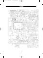
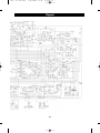
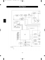
1
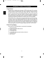
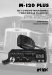
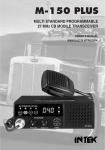
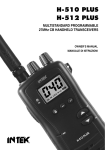
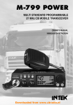
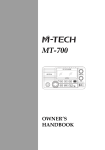
Man. M-790 PLUS
7-06-2005 17:20
Pagina 1
M-790 PLUS
MULTI STANDARD PROGRAMMABLE
27 MHz CB MOBILE TRANSCEIVER
OWNER'S MANUAL
MANUALE DI ISTRUZIONI
Man. M-790 PLUS
7-06-2005 17:20
Pagina 2
Declaration of Conformity
EC Certificate of Conformity
(to EC Directive 99/5-89/336-93/68-73/23)
DECLARATION OF CONFORMITY
With the present declaration, we certify that the following products :
INTEK M-790 PLUS
comply with all the technical regulations applicable to the above mentioned products
in accordance with the EC Directives 73/23/EEC, 89/336/EEC and 99/5/EC.
Type of product :
CB Transceiver
Details of applied standards :
EN 300 433, EN 300 135-2
EN 301 489-1, EN 301 489-13
EN 60065
Manufacturer :
INTEK S.R.L.
Via G. Marconi, 16
20090 Segrate, Italy
Tel. 39-02-26950451 / Fax. 39-02-26952185
E-mail : [email protected]
Notified Body :
EMCCert Dr. Rasek
Boelwiese 5, 91320 Ebermannstadt
Germany
Identification Number : 0678
Contact Reference :
Armando Zanni
Tel. 39-02-26950451 / Fax. 39-02-26952185
E-mail : [email protected]
Segrate, 30/05/2005
dr. Vittorio Zanetti
(General Manager)
Man. M-790 PLUS
7-06-2005 17:20
Pagina 3
Index
Index . . . . . . . . . . . . . . . . . . . . . . . . . . . . . . . . . . . . . . . . . . . . . . . . . . . . . . . . . . . .1
Content of the packaging . . . . . . . . . . . . . . . . . . . . . . . . . . . . . . . . . . . . . . . . . . . 2
Controls and operation . . . . . . . . . . . . . . . . . . . . . . . . . . . . . . . . . . . . . . . . . . 3 - 9
Installation . . . . . . . . . . . . . . . . . . . . . . . . . . . . . . . . . . . . . . . . . . . . . . . . . . . . 10-11
Frequency bands table . . . . . . . . . . . . . . . . . . . . . . . . . . . . . . . . . . . . . . . . . . . . 11
Frequency band selection / programming . . . . . . . . . . . . . . . . . . . . . . . . . . . . 12
Table of restrictions on the use of CB transceivers . . . . . . . . . . . . . . . . . . 12-13
Specifications . . . . . . . . . . . . . . . . . . . . . . . . . . . . . . . . . . . . . . . . . . . . . . . . . . . 14
ESP Compander Diagram . . . . . . . . . . . . . . . . . . . . . . . . . . . . . . . . . . . . . . . . . . 29
PCB - Main Board & CPU Board . . . . . . . . . . . . . . . . . . . . . . . . . . . . . . . . . . 30-31
Diagram . . . . . . . . . . . . . . . . . . . . . . . . . . . . . . . . . . . . . . . . . . . . . . . . . . . . . . 32-33
Block Diagram . . . . . . . . . . . . . . . . . . . . . . . . . . . . . . . . . . . . . . . . . . . . . . . . 34-35
Notes . . . . . . . . . . . . . . . . . . . . . . . . . . . . . . . . . . . . . . . . . . . . . . . . . . . . . . . . 36-37
NOTICE !
It is recommended to carefully read this owner’s manual before using the product. This
will also help the user to prevent using the radio in violation of the regulations valid in the
country where the product is used, as well as to avoid any possible interferences with
other services.
NOTICE !
Before using this transceiver, please check that the radio has been programmed on the
frequency bands, specifications and operating modes allowed by the regulations valid in
the country where the product is used. If not, please proceed to modify the frequency
band programming, as it is described in this owner’s manual. This transceiver is factory
pre-programmed on the CE European frequency band (CEPT 40CH FM 4W).
0678
CH
-1-
English
Introduction . . . . . . . . . . . . . . . . . . . . . . . . . . . . . . . . . . . . . . . . . . . . . . . . . . . . . . 2
Man. M-790 PLUS
7-06-2005 17:20
Pagina 4
Introduction - Content of the packaging
Congratulations!
English
Congratulations for selecting and purchasing an INTEK quality product. This transceiver
includes a number of advanced functions and systems, therefore it is definitely necessary
to carefully read this owner’s manual before using the radio. With a correct use of the
product in accordance with the operating method described in this manual, the product will
offer a trouble free use for many years. INTEK is constantly engaged to develop and
provide quality products meeting the customers requirements, however any suggestion or
comments on this product that might help us to improve quality are warmly welcome.
INTEK M-790 PLUS is a CB transceiver using advanced hardware and software design,
it includes a special multi-standard programmable circuit, which allows to program the
specifications of the radio (frequency bands, operating modes, transmitter power) in
compliance with the regulations valid in the various European countries. Therefore this
product can be used in any country of the European Community. The radio is delivered
factory pre-programmed on the CE European frequency band (CEPT 40CH FM 4W).
Content of the packaging
Please check that all the following items are contained in the packaging :
main unit (transceiver)
DC power cord with fuse holder and fuse
dynamic microphone
car mounting bracket
car mounting bracket accessories (hardware, knobs, etc.)
microphone bracket
owner’s manual
-2-
Man. M-790 PLUS
7-06-2005 17:20
Pagina 5
Controls and operation
1
2
3
4
5
6
DW
EMG
CHANNEL
SCAN
ESP
TX / RX
Q.UP
12
1.
OFF/VOL
SQUELCH
11
10
AM/FM
Q.DN
M-790 PLUS
LCR
9
8
7
DW / EMG Key
This key is used to enable the DW (Dual Watch) function and the EMG (Emergency
Channels) function.
DW (Dual Watch)
The DW (Dual Watch) function allows automatic monitoring of two programmable
channels. Refer to the following procedures to enable this function. Select the first
channel to monitor using the channel selector knob (6) or the channel selector keys
on the microphone (18, 20). Press the DW key for about 1.5 seconds and the DW
icon will blink on the LCD display. Select now the second channel to monitor,
following the same procedure. Finally press the DW key for about 1.5 seconds and
the two programmed channels will be alternately indicated on the LCD display. Radio
will automatically start monitoring (scanning) the two programmed channels. When a
signal is detected on one of the channels, scanning stops and it is possible to listen to
communication on that channel. It is possible to transmit on the channel, by pressing
the PTT key (17). If there is no transmission within 5 seconds, radio will start
scanning the two channels again. When the DW function is enabled, the DW icon (F)
appears on the LCD display. To exit the DW function, shortly press the DW key or the
PTT key (17).
-3-
English
Front panel
Man. M-790 PLUS
7-06-2005 17:20
Pagina 6
Controls and operation
English
EMG (Emergency Channels)
Shortly press the DW/EMG key to select the emergency channels. Two emergency
channels (CH9, CH19) are pre-programmed according to the selected frequency
band (refer to the following table). Each time the key is shortly pressed, radio selects
CH19, then CH9, then the normal operating channel. When an emergency channel is
selected (CH9, CH19), the EMG icon (N) appears on the LCD display.
COUNTRY
CODE
I0
I2
DE
D2
EU
CE
SP
FR
UK
PL
CH-9
AM
AM
AM
AM
AM
FM
AM
AM
AM
AM
CH-19
AM
AM
AM
AM
AM
FM
AM
AM
AM
AM
2.
SCAN Key
By pressing the SCAN key, the SCAN (automatic scanning of busy channels) function
is enabled. To enable the SCAN function, first turn the SQUELCH control (10)
clockwise, until the background noise is cut. Then press the SCAN key, radio will
automatically start scanning all channels continuously and the SCAN icon (O) will
appear on the LCD. Auto-scan stops if a signal is detected on a channel, in order to let
the user listen to the incoming signal and will start scanning again when no signal is
detected on that channel. It is possible to remain on that channel by pressing the PTT
key (17) within 5 seconds, otherwise radio will start scanning again. Auto-scan may be
also re-started at any time by pressing again the SCAN key. To exit the SCAN mode,
shortly press the PTT key (17).
3.
ESP (Electronic Speech Processor) Key
The ESP (Electronic Speech Processor) is an exclusive advanced feature in some of
the new INTEK mobile CB radios. ESP means Electronic Speech Processor, in other
words electronic modulation processor. This microprocessor controlled audio device
is also called COMPANDER (Compressor-Expander), it works as a modulation
compressor in transmission and as a modulation expander is receive mode. The ESP
allows to obtain a stronger, cleaner and clearer audio signal and it is a great help in
noisy areas, in case of long distance communication or with weak signals. The
efficiency of ESP is even greater when communicating with other radios having the
same system. To enable or disable the ESP function, press the ESP key. When the
ESP function is enabled, the ESP icon (M) appears on the LCD display.
100%
ESP performance
of the modulation
in RX and TX modes
0%
100%
Modulation without ESP
-4-
Modulation with ESP
Man. M-790 PLUS
7-06-2005 17:20
Pagina 7
4.
TX/RX Indicator
This green-red dual colour LED indicator lights up in green colour when radio is in
receive mode and in red colour when radio is in transmit mode.
5.
LCD Display
Large size LCD display with an orange colour backlighting system, for best
readability. The LCD display shows all the enabled functions as well as other
information programmable by the user, such as the programmed frequency band
code. It also includes a digital 10-bar S/RF Meter to monitor the strength/power of the
received and transmitted signals.
LCD Display
B
C
D
E
A
F
G
P
H
O
N
M
L
I
A. TX Icon
The TX icon is lighted when radio is in transmit mode.
B. RX Icon
The RX icon is lighted when radio is in receive mode.
C. FM Icon
The FM icon is lighted when radio receives and transmits in FM mode (frequency
modulation).
D. M Icon
Not used.
E. LOW Icon
The LOW icon is lighted when the transmitter is in the LOW POWER (1W) mode.
-5-
English
Controls and operation
Man. M-790 PLUS
7-06-2005 17:20
Pagina 8
Controls and operation
F.
English
DW Icon
The DW icon is lighted when the DUAL WATCH function (automatic monitoring of two
channels) is enabled.
G. Alphanumeric Digits
These two alphanumeric digits indicate the country code, in accordance with the
programmed frequency band (i.e. DE, UK, CE, etc.).
H. S/RF Digital Meter
A digital 10-bar S/RF METER indicates the strength of the received signal (from S0 to
S9+30) in the receive mode and the transmitter RF output power (0 to 4W) in the
transmit mode.
I.
AM Icon
The AM icon is lighted when radio receives and transmits in AM mode (amplitude
modulation).
L. LOCK Icon
The LOCK icon is lighted when the LOCK function has been enabled.
M. ESP Icon
The ESP icon is lighted when the ESP (Electronic Speech Processor) function has
been enabled. The ESP is an RX & TX electronic modulation processor.
N. EMG Icon
The EMG icon is lighted when one of the special pre-programmed emergency
channels has been selected.
O. SCAN Icon
The SCAN icon is lighted when the SCAN function (automatic search of busy
channels) is enabled.
P.
Alphanumeric Digits
These three numeric or alphanumeric digits indicate the operating channel number
(01 to 80, according to the programmed frequency band).
-6-
Man. M-790 PLUS
7-06-2005 17:20
Pagina 9
6.
CHANNEL Selector
This knob selects the channel number, by one channel steps. The knob may be
turned clockwise to select channels upward or counter clockwise to select channels
downward.
7.
Q.DN (Quick Down) Key
This key allows fast selection of the operating channel downward. Each time this key
is pressed, the channel number moves down by 10 channels.
8.
AM/FM and LCR Key
AM/FM SELECTOR
This key allows to select the AM or FM operating mode in both RX and TX. The
AM/FM operating mode selection is possible only if it is allowed the programmed
frequency band, otherwise the selection is not possible.
LCR
Pressing this key for about 1.5 seconds, the last used channel will be automatically
recalled.
UK / CE SELECTOR
If the UK frequency band has been programmed, shortly pressing this key, it will be
possible to select between the UK channels (frequencies) and the CE channels
(frequencies).
9.
Q.UP (Quick UP) Key
This key allows fast selection of the operating channel upward. Each time this key is
pressed, the channel number moves up by 10 channels.
10. SQUELCH Control
The SQUELCH control allows to silent the receiver by cutting the background noise.
Turn the SQUELCH knob clockwise until the background noise is cut. Turn the
SQUELCH knob counter clockwise (SQUELCH opening) to listen to the weakest
signals.
11. OFF/VOL (OFF / Volume) Control
This knob switches the radio ON and OFF and it adjusts the volume control. If no
signals are being received on the operating channel, it is suggested to open the
SQUELCH and adjust the volume to the desired level while listening to the
background noise.
12. MICROPHONE Connector
Connect the supplied dynamic microphone to this connector, locking it through the
ring nut.
-7-
English
Controls and operation
Man. M-790 PLUS
7-06-2005 17:20
Pagina 10
Controls and operation
Rear Panel
English
13
14
15
EXT
S-METER
ANTENNA
DC
13.2V
16
13. EXT (External Speaker) Jack
This jack is for connecting an external speaker (optional).
14. S-METER Jack
This jack is for connecting an external S-METER (optional).
15. ANTENNA Connector (SO-239)
Antenna connector. Refer to the section INSTALLATION OF THE ANTENNA.
16. 13.2VDC POWER CORD
13.2VDC power cord input.
IMPORTANT !
Do never attempt to open the cabinet of the transceiver. No user serviceable parts inside.
Internal modifications or tampering may cause damage to the product, modify its
technical specifications and will void warranty rights. If service or repair are required,
please go to an authorised service centre or specialized technician.
-8-
Man. M-790 PLUS
7-06-2005 17:20
Pagina 11
Controls and operation
17
18
19
20
21
17. PTT (Push-to-Talk) Key
Connect the supplied dynamic microphone to this connector, locking it by tightening
the ring nut.
18. UP (Channel Selector) Key
Each time this key is pressed, the channel number will move upward by one channel.
19. LOCK (Keypad Lock) Key
The LOCK function is enabled when pressing this key, in order lock the keypad and
prevent entering unwanted commands. When the LOCK function is enabled, the
LOCK icon (L) appears on the LCD display.
20. DOWN (Channel Selector) Key
Each time this key is pressed, the channel number will move downward by one
channel.
21. MICROPHONE Plug
6-pole microphone plug with locking ring nut, to be connected to the microphone
connector (21) located on the front side of the radio.
-9-
English
Microphone
Man. M-790 PLUS
7-06-2005 17:20
Pagina 12
Installation
Installation
English
Before installing the main unit in the vehicle, check and select the most convenient location, in
order that the radio will be easy to reach and comfortable to operate, without disturbing or
interfering with the vehicle drive. Use the supplied bracket and hardware to install the radio. The
bracket screws must be well tightened in order not to become loosen with the vehicle
vibrations. The car mounting bracket can be installed over or below the radio and the radio may
be inclined as desired according to the specific type of installation (under dashboard or track
cabin roof installation).
Installation of the Main Unit
Before connecting the radio to the vehicle electric system, make sure that radio is switched off,
with the OFF/VOL (11) knob completely turned counter clockwise at OFF position. The DC
power cable (16) of the radio is complete with a fuse holder with fuse located on the red positive
(+) wire. Connect the DC power cable to the vehicle electric system, with special attention to
respect correct polarity, even if the radio is protected against polarity inversion. Connect the red
wire to the positive (+) pole and the black wire to the negative (-) pole of the vehicle electric
system. Make sure that the wires and terminals are firmly and stably connected, in order to
prevent cables from disconnecting or causing short circuits.
Installation of the Antenna
A specific mobile antenna adjusted for 27 MHz frequency range must be used. The antenna
installation must be done by a specialised technician or service centre. Please pay special
attention to carefully install the antenna on the vehicle with perfect connection to ground. Before
connecting the antenna to the radio, it is necessary to check the correct operation of the
antenna with low standing wave ratio (S.W.R.), using adequate instruments. If not, the
transmitter circuit of the radio could be damaged. The antenna must be usually installed on the
highest part of the vehicle, free from obstacles and as far away as possible from any source of
electric or electromagnetic noise. The RF antenna coaxial cable must not be damaged or
pressed on its way between antenna and the radio. The correct operation of the antenna and
the low standing wave ratio (S.W.R.) must be checked periodically. Connect the RF antenna
coaxial cable to the antenna connector (15), located on the rear side of the radio.
- 10 -
Man. M-790 PLUS
7-06-2005 17:20
Pagina 13
Installation - Frequency bands table
Once radio has been connected to the vehicle electric system and to the antenna, the correct
operation of the system may be checked. Please proceed as follows :
1) Check that the power cable is correctly connected.
2) Check that the RF antenna coaxial cable is correctly connected.
3) Connect the microphone to the connector (12), located on the front side of the radio.
4) Rotate the SQUELCH (10) knob counter clockwise.
5) Turn radio on using the OFF/VOL (11) knob and adjust volume to the desired level.
6) Select the desired channel, using the channel selector knob (6) or the channel selector
keys on the microphone (18, 20).
7) Rotate the SQUELCH (10) knob clockwise, to cut the background noise.
8) Press the PTT (17) key to transmit and release it to receive.
9) Check the level of the received and transmitted signals on the digital bar S/RF Meter (H)
on the LCD display.
The transceiver will work correctly.
Frequency Bands Table
The transceiver INTEK M-790 PLUS includes an advanced multi-standard programmable
circuit, which allows to program different frequency bands, specifications and operating modes,
in conformity with the regulations in the country where the product is used. 10 programmable
frequency bands are available, as per the below table :
COUNTRY CODE
I0
I2
DE
D2
EU
CE
SP
FR
COUNTRY
ITALY
ITALY
GERMANY
GERMANY
EUROPE
CEPT
SPAIN
FRANCE
UK
UK
PL
POLAND
SPECIFICATIONS (CH, operating modes, TX power)
40CH AM / FM 4W
36CH AM / FM 4W
80CH FM 4W - 12CH AM 1W
40CH FM 4W - 12CH AM 1W
40CH FM 4W - 40CH AM 1W
40CH FM 4W
40CH AM / FM 4W
40CH FM 4W - 40CH AM 1W
40CH FM 4W UK FREQUENCIES 40CH FM 4W CEPT FREQUENCIES
40CH AM / FM 4W POLISH FREQUENCIES
Attention ! This radio has been factory pre-programmed on the CE frequency band (CEPT
40CH FM 4W), since this standard is currently accepted in all the European countries. Please
refer to the information table at page 13 (Restrictions on the use of CB transceivers).
- 11 -
English
Checking Operation of the Radio
Man. M-790 PLUS
7-06-2005 17:20
Pagina 14
Frequency band selection / programming
Frequency Band Selection / Programming
English
The radio must be programmed and used exclusively on a frequency band allowed in the
country where the product is used. It is possible to program a different frequency band, as per
the following procedures :
1) Switch off the radio.
2) Press and hold the EMG (1) key while turning on the radio, using the OFF/VOL (11)
knob.
3) The current country code (G) will blink on the LCD display (2 digits).
4) Now select the desired new country code, using the channel selector knob (6).
5) Shortly press the EMG (1) key to confirm.
Table of Restrictions on the Use of CB Transceivers
The following information are to be considered only just as an indication. They are believed to
be correct at the time of printing this operating manual. It is however the user’s responsibility to
check that, in the country where radio is used, the regulations for the use of CB transceivers
have not been modified. User is therefore suggested to contact the local dealer or local
authority, in order to check the current regulations for the use of CB transceivers, before
operating this product. The manufacturer does not take any responsibility if the product is used
in violation of the regulations of the country where the product is used.
Addendum (Updated information on national restrictions)
BELGIUM, UK, SPAIN, SWITZERLAND
In order to use this transceiver in Belgium, UK, Spain and Switzerland, residence must have an
individual licence. Users coming from abroad may freely use the radio in FM mode, while in
order to use it in AM mode they must hold a licence released in their own country.
ITALY
Foreigners arriving in Italy must get an Italian authorization.
AUSTRIA
Austria does not allow using multi standard programmable CB radios. It is recommended
to carefully follow this directives and not to use the product in the Austrian territory.
GERMANY
Along some border areas in Germany, the radio can not be used as a base station from
channel 41 to channel 80. Refer to local authority (notification office) for details.
- 12 -
Man. M-790 PLUS
7-06-2005 17:20
Pagina 15
Table of restrictions on the use of CB transceivers
BELGIUM
DENMARK
FINLAND
FRANCE
GERMANY
GREECE
IRELAND
ITALY
CB Introd.
Use restrictions and other comments
No
Not allowed
40 CH - 4W FM - Individual license is required
Yes
40 CH - 1W AM - Individual license is required
Yes
40 CH - 4W FM - Free use
40 CH - 4W FM - Free use
Yes
e 1W AM - Free use
40 CH - 4W FM - Free use
Si
40 CH - 1W AM - Free use
80 CH - 4W FM - Free use (restrictions for use as a base station on
channels 41-80 in some border areas)
12 CH - 1W AM - Free use
40 CH - 1W AM
Si
Free use (only CH 4-15 allowed)
40 CH - 4W FM - Free use
12 CH - 1W AM - Free use
REGTP Vfg41 issued on September 10, 2003
40 CH - 4W FM - Free use
Si
40 CH - 4W AM - Free use
T/R 20-02
40 CH - 4W FM - Free use
40 CH - 4W AM - Free use
Si
S.I. No 436 of 1998. WIRELESS TELEGRAPHY ACT, 1926 (SECTION3)
(EXEMPTION OF CITIZENS' BAND (CB) RADIOS)
ORDER, 1998
Si
LUXEMBOURG
Si
NORWAY
Si
NETHERLANDS
Si
PORTUGAL
Si
UNITED
KINGDOM
Si
SPAIN
Si
SWEDEN
Si
SWITZERLAND
Si
40 CH - 4W FM - A Declaration to the Italian Ministry is required
(art. 145 - dl 259 of 01/08/2003)
40 CH 1W AM - A Declaration to the Italian Ministry is required
(art. 145 - dl 259 of 01/08/2003)
34 CH - 4W FM, 1W AM (erp). Nota: AM mode allowed on CH1-CH23 only.
General authorisation is required (art. 104 - dl259 of 01/08/2003)
P.N.F. issued on DM 08.07.02 Notes: 49 A/B/C/D/E/G
40 CH - 4W FM - Free use. (Following frequencies are not allowed :
29.995, 27.045, 27.095, 27.145, 27.195 MHz)
40 CH - 4W FM - Free use
40 CH - 4W FM - Free use
40 CH - 1W AM - Free use
40 CH - 4W FM - Free use
40 CH - 1W AM - Free use
40 CH - 4W FM - Individual licence is required
UK-RA-MPT 1382/MPT1320; UK-R&TTE -S.IL. 2000:730
40 CH - 4W FM - Individual licence is required
40 CH - 4W AM - Individual licence is required
Ministerial decree of 18th November 2002 issued by "Secretaría de Estado
de Telecomunicaciones y para la Sociedad de la Información"
40 CH - 4W FM - Free use
40 CH - 1W AM - Individual licence is required
40 CH - 4W FM - Individual licence is required
40 CH - 1W AM - Individual licence is required
- 13 -
Settings
EU
CE
FR
EU
FR
EU
FR
CE
CE
CE
DE
EU
CE
D2
CE
EU
FR
SP
EU
FR
I0
SP
EU
FR
I0
CE
CE
I2
CE
EU
FR
EU
FR
UK
SP
CE
CE
CE
CE
EU
FR
EU
FR
EU
FR
CE
CE
CE
English
COUNTRY
AUSTRIA
Man. M-790 PLUS
7-06-2005 17:20
Pagina 16
Specifications
Specifications
General
English
Channels
Frequency range
Frequency control
Operatine temperature
DC input voltage
Size
Weight
40 FM (refer to the frequency bands table at page 11)
25.610 – 31.570 MHz
P.L.L.
-10°/+55°C
13.2Vdc ±15%
140 (L) x 37 (A) x 190 (P) mm
800 gr.
Receiver
System
IF
Sensitivity
Audio output
Audio distorsion
Image rejection
Adjacent channel
Signal/noise ratio
Current drain
Double conversion, CPU controlled super-eterodine
1° 10.695 MHz / 2° 455 KHz
0.5uV for 20dB SINAD (FM)
0.5uV for 20dB SINAD (AM)
@10% THD 2.5W at 8 ohm
<8% at 1 KHz
65dB
65dB
45dB
250mA (stand-by)
Trasmitter
System
Maximum RF power
Modulation
Impedance
Current drain
CPU controlled P.L.L. systhesizer
4W at 13.2Vdc
85% to 90% (AM)
1.8 KHz ±0.2 KHz (FM)
50 ohm unbalanced
1100mA (at no modulation)
- 14 -
Man. M-790 PLUS
7-06-2005 17:20
Pagina 17
Indice
Indice . . . . . . . . . . . . . . . . . . . . . . . . . . . . . . . . . . . . . . . . . . . . . . . . . . . . . . . . . . .15
Introduzione . . . . . . . . . . . . . . . . . . . . . . . . . . . . . . . . . . . . . . . . . . . . . . . . . . . . . 16
Contenuto della confezione . . . . . . . . . . . . . . . . . . . . . . . . . . . . . . . . . . . . . . . . 16
Descrizione dei comandi e funzionamento . . . . . . . . . . . . . . . . . . . . . . . . 17 - 23
Installazione e collegamenti elettrici . . . . . . . . . . . . . . . . . . . . . . . . . . . . . . 24-25
Tabella bande di frequenza . . . . . . . . . . . . . . . . . . . . . . . . . . . . . . . . . . . . . . . . . 25
Tabella delle restrizioni all' uso dei ricetrasmettitori CB . . . . . . . . . . . . . . 26-27
Caratteristiche tecniche . . . . . . . . . . . . . . . . . . . . . . . . . . . . . . . . . . . . . . . . . . . 28
Schema elettrico ESP Compander . . . . . . . . . . . . . . . . . . . . . . . . . . . . . . . . . . . 29
Circuito stampato Main Board e CPU . . . . . . . . . . . . . . . . . . . . . . . . . . . . . .30-31
Schema elettrico . . . . . . . . . . . . . . . . . . . . . . . . . . . . . . . . . . . . . . . . . . . . . . 32-33
Schema a blocchi . . . . . . . . . . . . . . . . . . . . . . . . . . . . . . . . . . . . . . . . . . . . . . 34-35
Note . . . . . . . . . . . . . . . . . . . . . . . . . . . . . . . . . . . . . . . . . . . . . . . . . . . . . . . . .36-37
IMPORTANTE !
Si consiglia vivamente di prendere visione del contenuto di quanto indicato in questo
manuale di istruzioni, prima di utilizzare la ricetrasmittente. Questo anche per evitare di
utilizzare l' apparecchio al di fuori dei limiti previsti dalle norme di legge in vigore nel
paese in cui la radio viene utilizzata, evitando anche possibili interferenze con altri servizi.
IMPORTANTE !
Prima di utilizzare la ricetrasmittente, verificare che la stessa sia programmata per
operare sulle bande di frequenza e nei modi previsti dalle norme di legge in vigore nel
paese in cui la radio viene utilizzata. Diversamente procedere alla modifica della
programmazione, come indicato in questo manuale di istruzioni. La radio è preprogrammata all' origine sulla banda di frequenza europea CE (CEPT 40CH FM 4W).
0678
CH
- 15 -
Italiano
Selezione / programmazione della banda di frequenza . . . . . . . . . . . . . . . . . . 26
Man. M-790 PLUS
7-06-2005 17:20
Pagina 18
Introduzione - Contenuto della confezione
Congratulazioni !
Italiano
Congratulazioni per aver scelto ed acquistato un prodotto di qualità INTEK. Questo
ricetrasmettitore dispone di numerose funzioni avanzate e vari dispositivi, pertanto è
assolutamente necessario leggere attentamente questo manuale di istruzioni prima di
utilizzare l' apparecchio. Con un uso corretto secondo quanto è indicato nel manuale di
istruzioni, l' apparecchio garantirà un servizio senza problemi per molti anni. Ci
impegnamo costantemente a fornire prodotti di qualità che rispondano alle vostre
esigenze, ma siamo comunque sempre molto interessati a ricevere eventuali vostri
commenti o suggerimenti su questo prodotto, che ci aiutino nel continuo miglioramento
della qualità.
INTEK M-790 PLUS è un ricetrasmettitore con caratteristiche tecniche di hardware e
software molto avanzate e dispone di un circuito di tipo Multi Standard programmabile
che consente di configurare i vari parametri dell' apparecchio (bande di frequenza, modi
operativi, potenza del trasmettitore) in modo conforme alle norme di legge in vigore nei
vari paesi della Comunità Europea. Pertanto questa ricetrasmittente può essere
utilizzata in un qualsiasi paese della Comunità Europea. L' apparecchio viene
consegnato pre-programmato sulla banda CE (CEPT 40CH FM 4W).
Contenuto della confezione
Verificare che le seguenti parti siano contenute nella confezione :
ricetrasmettitore
cavetto di alimentazione DC con porta fusibile e fusibile
microfono dinamico
staffa di montaggio per veicolo
accessori per montaggio staffa (viti, pomelli, ecc.)
staffa di supporto per microfono
manuale di istruzioni
- 16 -
Man. M-790 PLUS
7-06-2005 17:20
Pagina 19
Descrizione dei comandi e funzionamento
Pannello frontale
1
2
3
4
5
6
DW
SCAN
ESP
TX / RX
Q.UP
12
1.
OFF/VOL
SQUELCH
11
10
AM/FM
Q.DN
M-790 PLUS
LCR
9
8
7
Tasto DW / EMG
Questo tasto permette l’ inserimento delle funzioni DW (Dual Watch) e EMG
(Emergency Channels).
FUNZIONE DW (Dual Watch)
La funzione DW (Dual Watch) permette il monitoraggio automatico alternato di 2
canali programmabili. Per attivare questa funzione, eseguire la seguente procedura.
Selezionare il primo canale da monitorare tramite il selettore dei canali (6) o tramite i
tasti di selezione dei canali sul microfono (18, 20). Premere quindi il tasto DW (1) per
circa 1,5 secondi e l’ indicazione DW lampeggerà sul display LCD. Selezionale il
secondo canale da monitorare, con la stessa procedura. Infine premere ancora il
tasto DW (1) per circa 1,5 secondi e sul display LCD verrano indicati alternatamene i
due canali impostati. La radio inizia il controllo (scansione) automatico alternato di
questi due canali. Quando su uno di questi due canali viene rilevato un segnale, la
scansione si arresta ed è possibile ascoltare la comunicazione in corso su quel
canale. E’ possibile trasmettere sul canale premendo il tasto di trasmissione PTT
(17). Se non viene premuto il tasto di trasmissione entro 5 secondi, la radio
riprenderà automaticamente il controllo (scansione) dei due canali. Quando la
funzione DW è attiva, l’ icona DW (F) appare sul display LCD. Per uscire dalla
funzione DW, premere brevemente il tasto DW (1) oppure il tasto PTT (17).
- 17 -
Italiano
EMG
CHANNEL
Man. M-790 PLUS
7-06-2005 17:20
Pagina 20
Descrizione dei comandi e funzionamento
EMG (Emergency Channels)
Premere brevemente questo tasto per selezionare i canali di emergenza preprogrammati a seconda della banda di frequenza selezionata (vedi tabella seguente).
Ad ogni breve pressione del tasto, la radio seleziona il canale 19, quindi il canale 9,
quindi il normale canale in uso. Quando uno dei canali di emergenza (CH9, CH19) è
selezionato, sul display LCD appare l'icona EMG (N).
Italiano
CODICE
PAESE
I0
I2
DE
D2
EU
CE
SP
FR
UK
PL
CH-9
AM
AM
AM
AM
AM
FM
AM
AM
AM
AM
CH-19
AM
AM
AM
AM
AM
FM
AM
AM
AM
AM
2.
Tasto SCAN
Premendo il tasto SCAN (2), viene attivata la funzione SCAN (scansione), ovvero la
ricerca automatica dei canali occupati. Per abilitare questa funzione, ruotare prima la
manopola SQUELCH (10) in senso orario fino a quando sparisce il rumore di fondo. Se
durante la scansione viene rilevato un segnale, la scansione si arresta ed è possibile
ascoltare la comunicazione in corso su quel canale. E’ possibile trasmettere sul canale
premendo il tasto di trasmissione PTT (17). Se non viene premuto il tasto di
trasmissione entro 5 secondi, la radio riprenderà automaticamente il controllo
(scansione) dei due canali. Quando la funzione SCAN è attivata, l’ icona SCAN (P)
appare sul display LCD. Per uscire dalla funzione SCAN, premere brevemente il tasto
SCAN (2) oppure il tasto PTT (17).
3.
Tasto ESP (Electronic Speech Processor)
L’ ESP (Electronic Speech Processor) è un dispositivo esclusivo di alcuni
ricetrasmettitori CB mobili INTEK. ESP significa Electronic Speech Processor, cioè
processore elettronico di modulazione. Questo processore audio, controllato da
microprocessore e denominato anche COMPANDER (Compressor-Expander), lavora
come compressore di modulazione in trasmissione e come espansore di
modulazione in ricezione. L’ ESP consente di ottenere un segnale audio più forte,
chiaro e pulito ed è un notevole aiuto in zone rumorose, in caso di comunicazione a
lungo raggio e con segnali deboli. L’ efficienza dell’ ESP è maggiore se si comunica
con altre radio dotate dello stesso sistema. Per attivare o disattivare la funzione ESP,
premere il tasto ESP (3). L’ indicazione ESP (M) appare o scompare sul display.
100%
Azione del dispositivo ESP
sulla modulazione
in ricezione e trasmissione
0%
100%
Modulazione senza ESP
- 18 -
Modulazione con ESP
Man. M-790 PLUS
7-06-2005 17:20
Pagina 21
Descrizione dei comandi e funzionamento
Indicatore TX/RX
Questo indicatore LED luminoso bi-colore rosso-verde (4) è acceso in colore verde
quando il ricetrasmettitore è in modalità ricezione e in colore rosso quando il
ricetrasmettitore è in modalità trasmissione.
5.
Display LCD
Display LCD di grande dimensione e di tipo retroilluminato in colore arancione, per la
massima leggibilità. Il display indica tutte le funzioni e i dispositivi attivati e numerose
informazioni supplementari impostabili dall’ utente. Comprende inoltre uno strumento
indicatore tipo S/RF Meter digitale a 10 barre.
Italiano
4.
Display LCD
B
C
D
E
A
F
G
P
H
O
N
M
L
I
A. Indicazione TX
L’ indicazione TX è accesa quando il ricetrasmettitore è in modalità trasmissione.
B. Indicazione RX
L’ indicazione RX è accesa quando il ricetrasmettitore è in modalità ricezione.
C. Indicazione FM
L’ indicazione FM è accesa quando il ricetrasmettitore riceve e trasmette in modo FM
(modulazione di frequenza).
D. Indicazione M
Non attiva.
E. Indicazione LOW
L’ indicazione LOW è accesa quando il ricetrasmettitore trasmette in bassa potenza
(1W RF).
- 19 -
Man. M-790 PLUS
7-06-2005 17:20
Pagina 22
Descrizione dei comandi e funzionamento
F.
Indicazione DW
L’ indicazione DW è accesa quando è attiva la funzione DUAL WATCH, ovvero il
monitoraggio automatico di 2 canali.
G. Indicazione alfanumerica
Questa indicazione di 2 caratteri alfanumerici permette la lettura del codice di paese
(banda di frequenza) selezionato (es. DE, UK, CE, ecc.).
H. Strumento a barre S/RF Meter
Lo strumento digitale a 10 barre S/RF Meter indica l’ intensità del segnale ricevuto da
S0 a S9+30 in ricezione e la potenza RF di uscita da 0 a 4W in trasmissione.
Italiano
I.
Indicazione AM
L’ indicazione AM è accesa quando il ricetrasmettitore riceve e trasmette in modo AM
(modulazione di ampiezza).
L. Indicazione LOCK
L’ indicazione LOCK (lucchetto) è accesa quando è stata attivata la funzione LOCK,
ovvero il blocco dei comandi.
M. Indicazione ESP
L’ indicazione ESP è accesa quando è attivata la funzione ESP (Electronic Speech
Processor), ovvero il processore elettronico di modulazione RX e TX.
N. Indicazione EMG
L’ indicazione EMG (Emergency Channel) è accesa quando è stato selezionato uno
dei canali speciali di emergenza pre-programmati secondo la banda di frequenza
selezionata.
O. Indicazione SCAN
L’ indicazione SCAN (scansione) è accesa quando è attiva la funzione di scansione
SCAN, ovvero la ricerca automatica dei canali occupati.
P.
Indicazione alfanumerica
Questi tre caratteri alfanumerici indicano il numero del canale selezionato da 01 a 80,
secondo la banda di frequenza programmata).
- 20 -
Man. M-790 PLUS
7-06-2005 17:20
Pagina 23
6.
Manopola CHANNEL (selettore dei canali)
Questa manopola permette la selezione dei canali a scatti di 1 canale per volta, in
ordine crescente (manopola ruotata in senso orario) o decrescente (manopola
ruotata in senso antiorario).
7.
Tasto Q.DN (Quick Down)
Questo tasto permette la selezione rapida dei canali in ordine decrescente. Ad ogni
pressione del tasto il numero del canale viene diminuito di 10 canali per volta.
8.
Tasto AM/FM - LCR
SELETTORE AM/FM
Premendo brevemente questo tasto, verrà selezionato il modo operativo AM o FM, in
TX e RX, se il modo scelto è abilitato dalla banda di frequenza programmata.
LCR
Premendo questo tasto per circa 1,5 secondi, il ricetrasmettitore selezionerà
automaticamente l’ ultimo canale utilizzato.
SELETTORE UK / CE
Se è stata programmata la banda di frequenza UK (Gran Bretagna), premendo
brevemente questo tasto sarà possibile la selezione tra i canali (frequenze) CE e i
canali (frequenze) UK.
9.
Tasto Q.UP (Quick UP)
Questo tasto permette la selezione rapida dei canali in ordine crescente. Ad ogni
pressione del tasto il numero del canale viene aumentato di 10 canali per volta.
10. Manopola SQUELCH
Il comando SQUELCH permette di silenziare il ricevitore, eliminando il rumore
(fruscio) di fondo in assenza di segnali. Ruotare la manopola dello SQUELCH in
senso orario sino a quando scompare il rumore di fondo. Ruotare la manopola dello
SQUELCH in senso antiorario (apertura dello SQUELCH) per ascoltare i segnali più
deboli.
11. Manopola OFF/VOL (OFF / Volume)
Manopola di accensione e spegnimento della radio. Permette la regolazione del
volume di ascolto. In assenza di segnali sul canale in uso, si consiglia di aprire lo
SQUELCH e quindi di regolare il volume al livello desiderato utilizzando come
riferimento il rumore (fruscio) di fondo.
12. Presa per microfono
Collegare il microfono dinamico in dotazione a questa presa, bloccandolo tramite l’
apposita ghiera.
- 21 -
Italiano
Descrizione dei comandi e funzionamento
Man. M-790 PLUS
7-06-2005 17:20
Pagina 24
Descrizione dei comandi e funzionamento
Pannello posteriore
13
14
15
EXT
S-METER
ANTENNA
Italiano
DC
13.2V
16
13. Presa EXT (External Speaker)
Presa per il collegamento di un altoparlante esterno (opzionale).
14. Presa S-METER
Questa presa consente il collegamente di uno strumento di tipo S-METER esterno
(opzionale).
15. Connettore di antenna (SO-239)
Presa per il collegamento dell' antenna. Vedi capitolo installazione e collegamenti
elettrici.
16. Entrata POWER 13.2VDC
Entrata del cavetto di alimentazione DC in dotazione.
IMPORTANTE !
Non tentare mai di aprire il contenitore del ricetrasmettitore. All' interno dell' apparecchio
non vi sono parti utili o utilizzabili dall' utente. Interventi o manomissioni del circuito
interno della radio possono causare danni alla stessa o modificarne le caratteristiche
tecniche ed inoltre violano e invalidano il diritto alla garanzia. In caso di interventi tecnici,
rivolgersi esclusivamente ad tecnico o ad un centro di assistenza autorizzato.
- 22 -
Man. M-790 PLUS
7-06-2005 17:20
Pagina 25
Descrizione dei comandi e funzionamento
Microfono
18
19
20
Italiano
17
21
17. Tasto PTT (Push-to-Talk)
Tasto di trasmissione. Premere per trasmettere e mantenere premuto durante la
trasmissione e rilasciare per ritornare in modalità ricezione.
18. Tasto UP (selettore dei canali)
Tasto per la selezione dei canali in ordine crescente. Ad ogni pressione del tasto, il
numero del canale viene incrementato di un canale per volta.
19. Tasto LOCK (blocco della tastiera)
Premendo questo tasto, viene attivata la funzione LOCK (blocco della tastiera), al fine
di prevenire l' inserimento da tastiera di comandi accidentali e non voluti. Quando la
funzione LOCK è attivata l' icona LOCK (L) appare sul display.
20. Tasto DOWN (selettore dei canali)
Tasto per la selezione dei canali in ordine decrescente. Ad ogni pressione del tasto, il
numero del canale viene diminuito di un canale per volta.
21. Connettore microfono
Connettore del microfono a 6 poli con ghiera di fissaggio, da collegarsi alla apposita
presa (12) sul pannello frontale.
- 23 -
Man. M-790 PLUS
7-06-2005 17:20
Pagina 26
Installazione e collegamenti elettrici
Installazione del ricetrasmettitore
E' necessario verificare e localizzare sul veicolo la posizione più opportuna ove installare l'
apparato, in modo che sia pratico e confortevole l' utilizzo dello stesso e che l' ubicazione del
ricetrasmettitore non sia in nessun modo di ostacolo alla guida del veicolo. Per il montaggio del
ricetrasmettitore, utilizzare la staffa e le viti in dotazione. Le viti di fissaggio della staffa devono
essere ben serrate in modo che le vibrazioni del veicolo non possano allentarle. La staffa può
essere montata sia sopra sia sotto l' apparecchio a seconda del tipo di installazione richiesto. Il
ricetrasmettitore può anche essere inclinato e poi bloccato nella posizione desiderata tramite i 2
pomelli di fissaggio in dotazione.
Italiano
Collegamento elettrico del ricetrasmettitore
Prima di collegare l’ apparecchio al circuito elettrico del veicolo, assicurarsi che il
ricetrasmettitore sia spento, ovvero che la manopola OFF/VOL (11) sia girata completamente in
senso antiorario in posizione OFF. Il cavetto di alimentazione (16) del ricetrasmettitore è
completo di porta-fusibile con fusibile di protezione posto sul cavo rosso del positivo (+).
Collegare il cavetto di alimentazione al circuito elettrico del veicolo, facendo molta attenzione
nel rispettare la corretta polarità, anche se l’ apparecchio è protetto contro le inversioni di
polarità. Collegare il cavetto rosso al polo positivo (+) e il cavetto nero al polo negativo (-) del
circuito elettrico del veicolo. Assicurasi che il collegamento dei cavetti sia ben eseguito e che i
terminali siano ben fissati, per evitare che essi si possano staccare o causare corto circuiti.
Installazione e collegamento dell’ antenna
Deve essere utilizzata un’ antenna veicolare tarata sulle frequenze CB 27 MHz. L’ installazione
dell’ antenna deve essere eseguita da un tecnico specializzato. La massima attenzione deve
essere prestata nel montaggio dell’ antenna sul veicolo e nel collegamento della stessa alla
massa del veicolo. Prima del collegamento al ricetrasmettitore, è indispensabile che sia
verificato il corretto funzionamento dell’ antenna con basso livello di onde stazionarie (R.O.S.),
tramite apposita strumentazione. In caso contrario, il circuito trasmittente dell’ apparecchio
potrebbe venire danneggiato. L’ antenna deve essere normalmente montata sulla parte più alta
del veicolo, libera da ostacoli e il più possibile distante da fonti di disturbo elettrico o
elettromagnetico. Il cavetto coassiale RF dell’ antenna non deve essere danneggiato o
schiacciato nel percorso dall’ antenna al ricetrasmettitore. La corretta funzionalità dell’ antenna
ed il basso rapporto di onde stazionarie (R.O.S.) devono essere controllati periodicamente.
Collegare il cavo RF dell’ antenna all’ apposita presa di antenna (15), posta sul pannello
posteriore della radio.
- 24 -
Man. M-790 PLUS
7-06-2005 17:20
Pagina 27
Installazione e collegamenti elettrici - Tabella bande di frequenza
Una volta eseguiti i collegamenti elettrici del cavo di alimentazione e dell’ antenna, si può
controllare il corretto funzionamento del sistema. Procedere come segue :
1) Controllare che sia correttamente collegato il cavetto di alimentazione.
2) Controllare che sia correttamente collegato il cavetto coassiale RF dell’ antenna.
3) Collegare il microfono all’ apposita presa (12), posta sul pannello frontale della radio.
4) Ruotare il comando SQUELCH (10) in senso antiorario a inizio corsa.
5) Accendere l’ apparecchio tramite la manopola OFF/VOL (11) e regolare il volume di
ascolto al livello desiderato.
6) Selezionare il canale desiderato, tramite il selettore dei canali (6) o tramite i tasti di
selezione dei canali sul microfono (18 e 20).
7) Ruotare il comando SQUELCH (10) in senso orario, per eliminare il rumore di fondo.
8) Premere il tasto PTT (17) per trasmettere e quindi rilasciarlo per ricevere.
9) Verificare il livello del segnale ricevuto e del segnale trasmesso sull’ apposito strumento
digitale a barre S/RF Meter (H) sul display LCD (5).
Il ricetrasmettitore dovrà funzionare correttamente.
Tabella bande di frequenza
Il ricetrasmettitore INTEK M-790 PLUS dispone di un avanzato circuito multi-standard
programmabile, che consente di programmare la banda di frequenza, i parametri e i modi
operativi in conformità con le norme del paese in cui viene utilizzato l’ apparecchio. Sono
disponibili n. 10 bande programmabili, come dalla seguente tabella :
CODICE PAESE
I0
I2
DE
D2
EU
CE
SP
FR
PAESE
ITALIA
ITALIA
GERMANIA
GERMANIA
EUROPA
CEPT
SPAGNA
FRANCIA
UK
INGHILTERRA
PL
POLONIA
SPECIFICHE (Canali, modi operativi, potenza TX
40CH AM / FM 4W
36CH AM / FM 4W
80CH FM 4W - 12CH AM 1W
40CH FM 4W - 12CH AM 1W
40CH FM 4W - 40CH AM 1W
40CH FM 4W
40CH AM / FM 4W
40CH FM 4W - 40CH AM 1W
40CH FM 4W UK FREQUENCIES 40CH FM 4W CEPT FREQUENCIES
40CH AM / FM 4W POLISH FREQUENCIES
Attenzione ! Il ricetrasmettitore è stato pre-programmato all’ origine sulla banda di frequenza
con codice paese CE (CEPT 40CH FM 4W), in quanto questo standard è attualmente
riconosciuto in tutti i paesi europei. Vedere la tabella delle informazioni alla pag. 27 (Restrizioni
all’ uso dei ricetrasmettitori CB).
- 25 -
Italiano
Controllo del funzionamento del ricetrasmettitore
Man. M-790 PLUS
7-06-2005 17:20
Pagina 28
Selezione / programmazione della banda di frequenza
Selezione / programmazione della banda di frequenza
Italiano
Il ricetrasmettitore deve essere programmato e utilizzato esclusivamente su una banda di
frequenza ammessa nel paese in cui viene utilizzato l’ apparecchio. E’ possibile programmare
una diversa banda di frequenza, eseguendo la seguente procedura :
1) Spegnere il ricetrasmettitore.
2) Premere e mantenere premuto il tasto EMG (1), quindi accendere il ricetrasmettitore,
ruotando la manopola OFF/VOL (11).
3) Il codice di paese impostato di due caratteri (G) lampeggia sul display.
4) Selezionare ora il nuovo codice di paese desiderato, ruotando la manopola di
selezione dei canali (6).
5) Premere brevemente il tasto EMG (1) per confermare.
Tabella delle restrizioni all’ uso dei ricetrasmettitori CB
Le seguenti informazioni sono date a solo titolo indicativo. Si ritiene che le stesse siano corrette
al momento della stampa del presente manuale di istruzioni. E’ tuttavia responsabilità dell’
utilizzatore del ricetrasmettitore il verificare che, nel paese in cui viene utilizzato l’ apparecchio,
non siano state introdotte variazioni alle norme di legge che abbiano modificato le suddette
restrizioni. Si consiglia quindi l’ utilizzatore di consultare il proprio rivenditore di fiducia o l’
autorità locale al fine di verificare con esattezza le norme di legge in vigore e le restrizioni all’
uso per i ricetrasmettitori CB, prima di utilizzare il prodotto. Il produttore non assume alcuna
responsabilità per l’ uso del prodotto in modo non conforme a quanto è stabilito dalle norme di
legge, vigenti nel paese in cui il prodotto è utilizzato.
Addendum (Aggiornamento sulle restrizioni nazionali)
BELGIO, GRAN BRETAGNA, SPAGNA, SVIZZERA
Per poter utilizzare questo ricetrasmettitore in Belgio, Gran Bretagna, Spagna e Svizzera, i
residenti necessitano di una licenza individuale. Coloro che invece provengono dall’ estero
possono utilizzare liberamente l’ apparecchio in modo FM, mentre per utilizzarlo in modo AM
devono essere in possesso di una licenza rilasciata dal paese di origine.
ITALIA
Per gli stranieri che arrivano in Italia, è necessaria una autorizzazione italiana.
AUSTRIA
L’ Austria non autorizza l’ uso di ricetrasmettitori CB di tipo multi-standard (programmabili). Si consiglia
di rispettare scrupolosamente questa direttiva e di non utilizzare l’ apparecchio nel territorio austriaco.
GERMANIA
Lungo i confini di alcune zone della Germania, l’ utilizzo del ricetrasmettitore come stazione base dal
canale 41 al canale 80 non è ammesso. Rivolgersi all’ autorità locale (ufficio notifiche) per ulteriori dettagli.
- 26 -
Man. M-790 PLUS
7-06-2005 17:20
Pagina 29
Tabella delle restrizioni all' uso dei ricetrasmettitori CB
BELGIO
DANIMARCA
FINLANDIA
FRANCIA
GERMANIA
GRECIA
IRLANDA
ITALIA
Introd. CB
Restrizione all' uso e commenti
No
Non autorizzato
40 CH - 4W FM - Richiesta la licenza individuale
Si
40 CH - 1W AM - Richiesta la licenza individuale
Si
40 CH - 4W FM - Libero utilizzo
40 CH - 4W FM - Libero utilizzo
Si
e 1W AM - Libero utilizzo
40 CH - 4W FM - Libero utilizzo
Si
40 CH - 1W AM - Libero utilizzo
80 CH - 4W FM - Libero utilizzo (CH 41 - 80: uso limitato per stazioni base
in certe zone di confine)
12 CH - 1W AM - Libero utilizzo
40 CH - 1W AM - Libero utilizzo (autorizzati solamente i canali dal 4
Si
al 15)
40 CH - 4W FM - Libero utilizzo
12 CH - 1W AM - Libero utilizzo
REGTP Vfg41 rilasciato il 10 Settembre, 2003
40 CH - 4W FM - Libero utilizzo
Si
40 CH - 4W AM - Libero utilizzo
T/R 20-02
40 CH - 4W FM - Libero utilizzo
40 CH - 4W AM - Libero utilizzo
Si
S.I. No 436 of 1998. WIRELESS TELEGRAPHY ACT, 1926 (SECTION3)
(ESENZIONE PER LE RADIO CB OPERANTI SULLA BANDA CITTADINA)
ORDER, 1998
Si
LUSSEMBURGO
Si
NORVEGIA
Si
OLANDA
Si
PORTOGALLO
Si
REGNO UNITO
Si
SPAGNA
Si
SVEZIA
Si
SVIZZERA
Si
40 CH - 4W FM - Richiesta una dichiarazione al Ministero
(art. 145 - dl 259 del 01/08/2003)
40 CH 1W AM - Richiesta una dichiarazione al Ministero
(art. 145 - dl 259 del 01/08/2003)
34 CH - 4W FM, 1W AM (erp). Nota: uso AM ammesso solo su CH1-CH23.
Richiesta autorizzazione generale (art. 104 - dl259 del 01/08/2003)
P.N.F. pubblicato su DM 08.07.02 Note: 49 A/B/C/D/E/G
40 CH - 4W FM - Libero utilizzo. (Uso non ammesso su frequenze :
29.995, 27.045, 27.095, 27.145, 27.195 MHz)
40 CH - 4W FM - Libero utilizzo
40 CH - 4W FM - Libero utilizzo
40 CH - 1W AM - Libero utilizzo
40 CH - 4W FM - Libero utilizzo
40 CH - 1W AM - Libero utilizzo
40 CH - 4W FM - Richiesta la licenza individuale
UK-RA-MPT 1382/MPT1320; UK-R&TTE -S.IL. 2000:730
40 CH - 4W FM - Richiesta la licenza individuale
40 CH - 4W AM - Richiesta la licenza individuale
Decreto Ministeriale del 18 novembre 2002 rilasciato da "Secretaría de
Estado de Telecomunicaciones y para la Sociedad de la Información"
40 CH - 4W FM - Libero utilizzo
40 CH - 1W AM - Richiesta la licenza individuale
40 CH - 4W FM - Richiesta la licenza individuale
40 CH - 1W AM - Richiesta la licenza individuale
- 27 -
Impostazioni
EU
CE
FR
EU
FR
EU
FR
CE
CE
CE
DE
EU
CE
D2
CE
EU
FR
SP
EU
FR
I0
SP
EU
FR
I0
CE
CE
I2
CE
EU
FR
EU
FR
UK
SP
CE
CE
CE
CE
EU
FR
EU
FR
EU
FR
CE
CE
CE
Italiano
PAESE
AUSTRIA
Man. M-790 PLUS
7-06-2005 17:20
Pagina 30
Caratteristiche tecniche
Caratteristiche tecniche
Generali
Canali
Gamma di frequenza
Controllo di frequenza
Temperatura di lavoro
Tensione di alimentazione
Dimensioni
Peso
40 FM (vedere tabella bande di frequenza a pag. 25)
25.610 - 31.570 MHz
P.L.L.
-10°/+55°C
13.2Vdc ±15%
140 (L) x 37 (A) x 190 (P) mm
800 gr.
Italiano
Ricevitore
Sistema
IF
Sensibilità
Uscita audio
Distorsione audio
Reiezione alle immagini
Canale adiacente
Rapporto segnale/rumore
Consumo
Super-eterodina a doppia conversione, controllato da CPU
1° 10.695 MHz / 2° 455 KHz
0.5uV per 20dB SINAD (FM)
0.5uV per 20dB SINAD (AM)
@10% THD 2.5W a 8 ohm
<8% a 1 KHz
65dB
65dB
45dB
250mA (stand-by)
Trasmettitore
Sistema
Potenza RF massima
Modulazione
Impedenza
Consumo
Sintetizzatore P.L.L. controllato da CPU
4W a 13.2Vdc
da 85% a 90% (AM)
1.8 KHz ±0.2 KHz (FM)
50 ohm sbilanciati
1100mA (senza modulazione)
- 28 -
Man. M-790 PLUS
7-06-2005 17:20
Pagina 31
ESP Compander Diagram
- 29 -
Man. M-790 PLUS
7-06-2005 17:20
Pagina 32
PCB - Main Board & CPU Board
- 30 -
Man. M-790 PLUS
7-06-2005 17:20
Pagina 33
PCB - Main Board & CPU Board
- 31 -
Man. M-790 PLUS
7-06-2005 17:20
Pagina 34
Diagram
- 32 -
Man. M-790 PLUS
7-06-2005 17:20
Pagina 35
Diagram
- 33 -
Man. M-790 PLUS
7-06-2005 17:20
Pagina 36
Block Diagram
Italiano
- 34 -
7-06-2005 17:20
Pagina 37
Block Diagram
Italiano
Man. M-790 PLUS
- 35 -
Man. M-790 PLUS
7-06-2005 17:20
Pagina 38
Notes
- 36 -
Man. M-790 PLUS
7-06-2005 17:20
Pagina 39
Notes
- 37 -
Man. M-790 PLUS
7-06-2005 17:20
Pagina 40