1
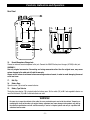
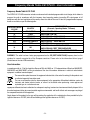
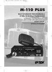
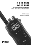
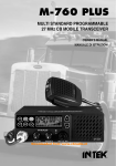
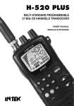
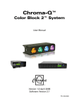
H-510 PLUS
H-512 PLUS
MULTISTANDARD PROGRAMMABLE
27MHz CB HANDHELD TRANSCEIVERS
OWNER'S MANUAL
MANUALE DI ISTRUZIONI
Index - Introduction - Content of the Package
Index - Introduction - Content of the package . . . . . . . . . . . . . . . . . . . . . . . . . . . . . . . . . . . . . . . . . . . . . . . . 1
Controls, indicators and operation . . . . . . . . . . . . . . . . . . . . . . . . . . . . . . . . . . . . . . . . . . . . . . . . . . . . . . . 2 - 5
Battery operation . . . . . . . . . . . . . . . . . . . . . . . . . . . . . . . . . . . . . . . . . . . . . . . . . . . . . . . . . . . . . . . . . . . . . . . . 6
Car adaptor operation . . . . . . . . . . . . . . . . . . . . . . . . . . . . . . . . . . . . . . . . . . . . . . . . . . . . . . . . . . . . . . . . . . . . 7
Frequency bands table H-510 PLUS . . . . . . . . . . . . . . . . . . . . . . . . . . . . . . . . . . . . . . . . . . . . . . . . . . . . . . . . 8
Frequency bands table H-512 PLUS - User Information . . . . . . . . . . . . . . . . . . . . . . . . . . . . . . . . . . . . . . . . 9
Frequency band selection / programming . . . . . . . . . . . . . . . . . . . . . . . . . . . . . . . . . . . . . . . . . . . . . . . . . . 10
Table of restrictions on the use of CB transceivers . . . . . . . . . . . . . . . . . . . . . . . . . . . . . . . . . . . . . . . . . . . 10
Specifications - Optional Accessories . . . . . . . . . . . . . . . . . . . . . . . . . . . . . . . . . . . . . . . . . . . . . . . . . . . . . . 11
Table of restrictions on the use of CB transceivers . . . . . . . . . . . . . . . . . . . . . . . . . . . . . . . . . . . . . . . . . . . . I
PCB - Main Board . . . . . . . . . . . . . . . . . . . . . . . . . . . . . . . . . . . . . . . . . . . . . . . . . . . . . . . . . . . . . . . . . . . . II - III
Diagram . . . . . . . . . . . . . . . . . . . . . . . . . . . . . . . . . . . . . . . . . . . . . . . . . . . . . . . . . . . . . . . . . . . . . . . . . . . .IV - V
Block Diagram . . . . . . . . . . . . . . . . . . . . . . . . . . . . . . . . . . . . . . . . . . . . . . . . . . . . . . . . . . . . . . . . . . . . . . VI-VII
Declaration of Conformity H-510 PLUS . . . . . . . . . . . . . . . . . . . . . . . . . . . . . . . . . . . . . . . . . . . . . . . . . . . . VIII
Declaration of Conformity H-512 PLUS . . . . . . . . . . . . . . . . . . . . . . . . . . . . . . . . . . . . . . . . . . . . . . . . . . . . . IX
NOTICE !
Before using this transceiver, please check that the radio has been programmed on the frequency band,
specifications and operating modes allowed by the regulations valid in the country where the product is used. If
not, please proceed to modify the frequency band programming, as it is described in this owner’s manual. This
transceiver is factory pre-programmed on the CE European frequency band CEPT 40CH FM 4W (H-512 PLUS) or on
the E1 band 40CH AM 4W (H-510 PLUS).
It is recommended to carefully read this owner’s manual before using the product. This will also help the user to
prevent using the radio in violation of the regulations valid in the country where the product is used, as well as to
avoid any possible interferences with other services.
Congratulations!
Congratulations for selecting and purchasing an INTEK quality product. This transceiver includes a number of advanced
functions and systems, therefore it is definitely necessary to carefully read this owner’s manual before using the radio.
With a correct use of the product in accordance with the operating method described in this manual, the product will offer
a trouble free use for many years. INTEK is constantly engaged to develop and provide quality products meeting the
customers requirements, however any suggestion or comments on this product that might help us to improve quality are
warmly welcome. This transceiver has advanced hardware and software design, it includes a special multi-standard
programmable circuit, which allows to program the specifications of the radio (frequency bands, operating modes,
transmitter power) in compliance with the regulations valid in the various European countries. Therefore this product
can be used in any country of the European Community. Using this two-way radio is quite easy and only a few minutes
are required to get familiar with it. The operating method and design are the results of years of experience in the
development and production of RF communication equipment, for personal an professional use. However it is strongly
recommended to carefully read this manual in order to get the maximum performances from your transceiver.
Content of the Package
Please carefully check that all the following items are contained in the packaging :
Transceiver
Rubber antenna
Belt clip with mounting hardware
Carrying strap
User manual
-1-
Controls, Indicators and Operation
Front Panel
2
1
2
3
1
3
4
4
5
15
5
15
TX
TX
AM FM LOCK HI LO
AM FM LOCK HI LO
14
13
14
6
H/L
13
12
H/L
6
A/F
12
UP
UP
7
7
MIC
8
MIC
8
DN
DN
11
11
H-510 PLUS
H-512 PLUS
9
9
AM CB TRANSCEIVER
AM/FM CB TRANSCEIVER
10
10
H-510 PLUS
H-512 PLUS
1.
Antenna Connector
Connect the supplied rubber antenna to this BNC connector, insert and gently turn it clockwise until blocked.
Do not overtighten. If the antenna is not or not correctly connected, damage may be caused to the radio.
2.
SQ/SQL Control
SQL CONTROL (SQUELCH manual adjustment)
The SQL control allows to silent the receiver by cutting the background noise, when no signals are received. Turn the
knob clockwise until the background noise is cut. Turn the knob counter clockwise (SQUELCH opening) in order to listen
to the weakest signals.
SQ CONTROL (SQUELCH fixed setting)
The SQ function allows to automatically silent the receiver, avoding the SQUELCH manual adjustment. A fixed
SQUELCH threshold is factory pre-set. To enable the fixed SQUELCH function, turn the knob fully counter clockwise to
the SQ position, until a click noise is heard.
-2-
Controls, Indicators and Operation
3.
VOL (OFF/Volume) Control
This knob switches the radio ON and OFF and it adjusts the volume control. If no signals are being received on the
operating channel, it is suggested to open the SQUELCH and adjust the volume to the desired level while listening to the
background noise.
4.
Handstrap Hole
Hole to insert and attach the supplied carrying handstrap.
5.
LCD Display
Large size LCD display with green color backlight function for best readability in darkness. It indicates
simultaneously all the programmed settings and all the enabled functions, such as the operating channel
number, the operating mode and 4-bar battery level indicator.
LCD Display
A
G
AM FM LOCK HI LO
F
B
C
E
D
A. Channel Number
It indicates the operating channel number or the frequency band ID code.
B. Battery Level Indicator
It shows the current battery level condition.
C. LO Icon
The LO Icon (C) is lighted when the transmitter is in LOW POWER mode (1W).
D. Icona HI
The HI Icon (D) is lighted when the transmitter is in HIGH POWER mode (4W).
E.
LOCK Icon
The LOCK icon (E) is lighted when the keypad lock function has been enabled.
F.
FM Icon (H-512 PLUS)
The FM icon (F) is lighted when radio has been set to the FM (Frequency Modulation) operating mode.
G. AM Icon
The AM icon is lighted when radio has been set to the AM (Amplitude Modulation) operating mode.
-3-
Controls, Indicators and Operation
6.
LIGHT Key (H-510 PLUS)
Press the LIGHT (6) key to backlight the LCD display, press the key again to switch OFF backlight.
A/F (AM/FM) Key (H-512 PLUS)
Use the AF key to select the AM or FM operating mode in both RX and TX. The AM/FM operating mode selection is
possible only if it is allowed by the programmed frequency band, otherwise the AM/FM selection is not possible.
7.
UP (QUICK UP) Key
Shortly press the UP (9) key to increase the channel number by one channel up at every key press. By keeping this key
pressed, the quick channel selection mode will be enabled.
8.
DN (QUICK DN) Key
Shortly press the DN (8) key to decrease the channel number by one channel down at every key press. By keeping this
key pressed, the quick channel selection mode will be enabled.
9.
Built-in Speaker
Built-in front speaker.
10. Car Adaptor Contacts
Car adaptor contacs and fixing screw.
11. Built-in Microphone
Built-in microphone.
12. H/L Key
The transmitter RF output power is selectable in 2 levels (1.0W or 4.0W). This function is very convenient to reduce the
current drain and extend battery life when communicating within short distance. The 4W RF output power level is
available only if it is allowed by the programmed frequency band. Press H/L (12) key to select the transmitter RF output
power HI (High Power 4W) or LO (Low Power 1W). The HI (D) or LO (C) icons will appear on the LCD Display (5).
13. LOCK / Keypad Tone Key
LOCK
Press the LOCK (13) key for a few seconds to enable the keypad LOCK function. Press the key again to disable.
KEYPAD PROGRAM TONE
When a key is pressed, a beep tone is heard to confirm your command. To enable or disable this keypad program tone
press and keep pressed the LOCK (13) key while switching ON radio, by turning the VOL (3) control clockwise.
14. PTT (Push-To-Talk) Key
Press the PTT (14) key to transmit and hold it during transmission. The TX LED indicator (15) will be lighted during
transmission. Release the key at the end of your transmission to return to the receive mode.
WARNING ! Do not touch the antenna during transmission.
15. TX LED
This red color LED indicator (15) lights up when radio is in transmit mode.
-4-
Controls, Indicators and Operation
Rear Panel
16
17
+
-
-
+
-
+
-
+
-
+
-
NI
AL
18
+
19
16. Earset-Microphone-Charge Jack
Connect an external earset-microphone to this jack. Connect the 230VAC battery travel charger (AC-520) to this jack.
WARNING !
Use only original accessories. Connecting and using accessories other than the original ones, may cause
serious damage to the radio and will void the warranty.
Always set the volume to minimum before connecting an external earset, in order to avoid damaging the earset
or the user’s ear.
17.
Belt Clip
18. Battery Door
Open this cover (18) to install or remove batteries.
19. Battery Type Selector
The battery type selector (18) is located inside the battery room. Set the switch (19) to Ni if rechargeable batteries are
used. Set the switch (19) to AL if alkaline batteries are used.
WARNING !
Do never try to open the cabinet of the radio. No user serviceable parts are inside the cabinet. Tampering or
modifying the circuit of the radio or its original factory adjustment may cause damage to the product, may change
the electrical specifications and will void the warranty. If service is required, please refer only to a qualified and
authorized service center.
-5-
Battery Operation
Installing and Checking Batteries
Slide down and remove the battery door (18) to access the battery room. Set the battery type switch (19) according to
the type of used batteries (Ni for rechargeable batteries and AL for alkaline batteries). Install 6 x AA size alkaline
batteries or rechargeable batteries and pay attention to install it with the correct polarity as indicated in the battery
room. Switch ON radio by turning the OFF/VOL (3) control and check the battery level on the battery level indicator
(B), 4 bars mean full charge, 3 bars mean normal charge, 2 bars mean half charge and 1 bar means low battery
condition. If no bars appear, batteries must be immediately replaced or recharged. Please refer to the following item
BATTERY CHARGING.
Battery Charging
If the battery level indicator (B) shows a low battery condition, switch OFF the radio and connect the battery travel
charger mod. AC-520 to the CHARGE jack (16), then plug it into the 230VAC outlet. To obtain the maximum
performance from the batteries, recharge them only when they are fully discharged. The charging time depends on the
capacity of the used batteries, it is approximately 12 hours for one set of Ni-MH batteries (1200-1500mAh). When the
charging time has expired, unplug the charger from the AC outlet and then disconnect it from the radio.
WARNING !
1.
Only the Ni-MH (or Ni-CD) batteries may be recharged.
2.
Do never try to recharge alkaline batteries, as this might cause damage to the radio or explosion of the
batteries.
3.
Set the battery type selector (19) to Ni.
4.
Always switch OFF radio before starting the battery charging process.
5.
Do not recharge batteries for more than 13-14 hours, in order to avoid overcharge or overheating, which could
cause damage to the radio.
6.
Use only the enclosed battery charger or original INTEK battery chargers.
-6-
Frequency Bands Table H-510 PLUS
Frequency Bands Table H-510 PLUS
The INTEK H-510 PLUS transceiver includes an advanced multi-standard programmable circuit design, which allows to
program the radio in accordance with the frequency band, operating modes, transmitter RF output power in full
compliance with the local regulations of the country where the radio will be used. A total of 5 programmable frequency
bands are available, as per the following table :
FREQUENCY BAND
ID CODE
E1
I2
DE
EU
PL
SPECIFICATIONS
(Channels, Operating Modes, TX Power)
COUNTRY
ITALY/SPAIN
ITALY
GERMANY
EUROPE/FRANCE
POLAND
40CH AM
36CH AM
12CH AM 1W
40CH AM 1W
40CH AM POLISH FREQUENCIES
WARNING ! The radio has been factory pre-programmed on the E1 (40CH AM 4W) frequency band, as this standard is
currently accepted by some countries (Italy and Spain). Please refer to the information table at page I (Restrictions on
the use of CB transceivers).
-8-
Frequency Bands Table H-512 PLUS - User Information
Frequency Bands Table H-512 PLUS
The INTEK H-512 PLUS transceiver includes an advanced multi-standard programmable circuit design, which allows to
program the radio in accordance with the frequency band, operating modes, transmitter RF output power in full
compliance with the local regulations of the country where the radio will be used. A total of 8 programmable frequency
bands are available, as per the following table :
FREQUENCY BAND
ID CODE
E1
I2
DE
D2
EU
CE
ITALY/SPAIN
ITALY
GERMANY
GERMANY
EUROPE/FRANCE
CEPT
U
UK
PL
POLAND
SPECIFICATIONS
(Channels, Operating Modes, TX Power)
COUNTRY
40CH AM / FM 4W
36CH AM / FM 4W
80CH FM 4W - 12CH AM 1W
40CH FM 4W - 12CH AM 1W
40CH FM 4W - 40CH AM 1W
40CH FM 4W
40CH FM 4W UK FREQUENCIES
40CH FM 4W CEPT FREQUENCIES
40CH AM / FM 4W POLISH FREQUENCIES
WARNING ! The radio has been factory pre-programmed on the CE (CEPT 40CH FM 4W) frequency band, as this
standard is currently accepted by all the European countries. Please refer to the information table at page I
(Restrictions on the use of CB transceivers).
User Information
in accordance with art. 13 of the Legislative Decree of 25th July 2005, no. 15 ”Implementation of Directives 2002/95/EC,
2002/96/EC and 2003/108/EC, relative to reduction of the use of hazardous substances in electrical and electronic
equipment, in addition to waste disposal”.
The crossed bin symbol shown on the equipment indicates that at the end of its working life the product must
be collected separately from other waste.
The user must therefore take the above equipment to the appropriate differentiated collection centres for
electronic and electro technical waste, or return it to the dealer when purchasing a new appliance of
equivalent type, in a ratio of one to one.
Appropriate differentiated waste collection for subsequent recycling, treatment and environment-friendly disposal of the
discarded equipment helps to prevent possible negative environmental and health effects and encourages recycling of
the component materials of the equipment.
Illegal disposal of the product by the user will be punished by application of the administrative fines provided for by the
legislative decree no. 22/1997 (article 50 and following of the legislative decree no. 22/1997).
-9-
Frequency Bands Selection / Programming
Frequency Band Selection / Programming
The radio must be programmed and used exclusively on the frequency band allowed by the regulations of the country
where the radio will be used. In order to program the frequency band, please refer to the following instructions :
1.
Turn OFF radio.
2.
Press and keep pressed the PTT (14) key while switching ON radio, by turning the OFF/VOL (3) control
clockwise.
3.
The current programmed frequency band ID code (A) appears on the LCD.
4.
Using the UP (7) or DN (8) keys, select a new frequency band ID code.
5.
Shortly press the PTT (14) key to confirm and store.
UK/CE CHANNELS SELECTION (FREQUENCY BAND "U") (H-512 PLUS)
If the frequency band "U" (UK band) has been selected, all channels can be scrolled using the channel keys. When a
UK frequency channel will be selected the display (5) will show the channel number and the indication "U". When a
CEPT frequency channel will be selected the display (5) will show the channel number and the indication "C".
Table of Restrictions on the Use of CB Transceivers (page I)
The following information are to be considered only just as an indication. They are believed to be correct at the time of
printing this operating manual. It is however the user’s responsibility to check that, in the country where radio is used, the
regulations for the use of CB transceivers have not been modified. User is therefore suggested to contact the local
dealer or local authority, in order to check the current regulations for the use of CB transceivers, before operating this
product. The manufacturer does not take any responsibility if the product is used in violation of the regulations of the
country where the product is used.
Addendum (Updated information on national restrictions)
BELGIUM, UK, SPAIN, SWITZERLAND
In order to use this transceiver in Belgium, UK, Spain and Switzerland, residence must have an individual licence. Users
coming from abroad may freely use the radio in FM mode, while in order to use it in AM mode they must hold a licence
released in their own country.
ITALY
Foreigners arriving in Italy must get an Italian authorization.
AUSTRIA
Austria does not allow using multi standard programmable CB radios. It is recommended to carefully follow this
directives and not to use the product in the Austrian territory.
GERMANY
Along some border areas in Germany, the radio can not be used as a base station from channel 41 to channel 80. Refer
to local authority (notification office) for details.
- 10 -
Specifications - Optional Accessories
Specifications
General
Channels
Frequency band
Frequency control
Operatine temperature
DC input voltage
Size
Weight
Refer to the frequency bands table at pages 8-9
27 MHz Citizen Band
P.L.L.
-10°/+55°C
9.0V (6 x AAA 1.5V alkaline battery)
7.2V (6 x AAA 1.2V Ni-MH battery)
68 (L) x 146 (H) x 38 (D) mm
185 gr. (without batteries and antenna)
Receiver
System
IF
Sensitivity
Audio output
Audio distorsion
Image rejection
Adjacent channel
Signal/noise ratio
Current drain
Double conversion, CPU controlled super-eterodine
1° 10.695 MHz / 2° 455 KHz
0.5uV for 20dB SINAD (FM) (H-512 PLUS)
0.7uV for 20dB SINAD (AM)
0.3W at 8 ohm
<8% at 1 KHz
61dB
61dB
45dB
70mA (stand-by)
Transmitter
System
Maximum RF power
Modulation
Impedance
Current drain
CPU controlled P.L.L. systhesizer
4W at 9.0Vdc
AM/FM (H-512 PLUS)
AM
50 ohm unbalanced
1500mA (at no modulation)
- 11 -