1
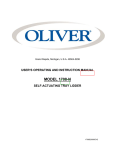
Grand Rapids, Michigan, U.S.A. 49504-5298 USER’S OPERATING AND INSTRUCTION MANUAL MODEL 1508-NLG SELF-ACTUATING TRAY LIDDER 1508S20000CV2 1508-NLG SELF-ACTUATING LIDDER INDEX SAFETY INSTRUCTIONS........................................................................................... 1508S20002 SET UP........................................................................................................................ 1508S20003 OPERATING PROCEDURE......................................................................................... 1508S20004 ADJUSTMENTS........................................................................................................... 1508S20005 TECHNICAL SPECIFICATIONS................................................................................... 1508S20006 CLEANING................................................................................................................... 1508S20007 TROUBLE SHOOTING................................................................................................. 1508S20012-1 PUSHER ADJUSTMENTS............................................................................................ 1508S20012-2 ASSEMBLIES BASE ASSEMBLY................................................................................................... 1508S20008 HEATER PLATTEN ASSEMBLY ........................................................................... 1508S20009 MANIFOLD ASSEMBLY......................................................................................... 1508S20010 FINAL ASSEMBLY.................................................................................................. 1508S20011 MACHINE EXCHANGE PROGRAM............................................................................. GEN 050819 WARRANTY.................................................................................................................. GEN 040225 WARRANTY PROCEDURE.......................................................................................... GEN 040226 RETURNED PARTS POLICY....................................................................................... GEN 040227 12/23/97 1508S20001 1508-NLG SELF-ACTUATING LIDDER SAFETY Various safety devices and methods of guarding have been provided on this machine. It is essential, however, that machine operators and maintenance personnel observe the following safety precautions. Improper installation or operation of this equipment may cause injury to personnel or damage to equipment. • Before operating the Self-Actuating Lidder read through this manual. Never allow an untrained person to operate this machine. WARNING • WARNING PINCH POINT: Keep hands out of machine. Always be sure the machine has been unplugged from power and air before cleaning or servicing. CAUTION • CAUTION HOT: The heater cover and upper platen are very HOT! Caution must be used to protect yourself and others. • In addition to these general safety instructions, follow the specific instructions given through out this manual. 12/17/97 1508S20002 1508-NLG SELF-ACTUATING LIDDER SET UP 1. Unpack and carefully remove the Self-Actuating Lidder. Check for completeness of your order and that none of the items have been damaged during shipment. 2. Screw the four rubber feet in to place on the bottom of the machine. 3. Place the Self-Actuating Lidder in a suitable location that provides adequate working space. The location must be sturdy, level, and capable of holding 50 lbs. per machine. 4. Use the quick detachable coupler to connect air pressure to the filter/regulator. The Self- Actuating Lidder requires a minimum of 0.1 CFM at 90 PSI. NOTE • DO NOT USE AN OILER OR LUBRICATOR WITH THIS MACHINE. NOTE • DO NOT CONNECT TO AIR PRESSURE ABOVE 140 PSI. 5. Pull the ejector bar to its operating position as shown. 11/9/09 1508S20003-1 1508-NLG SELF-ACTUATING LIDDER 6. SET UP (continued) 6. Plug the power cord into a grounded electrical outlet. The Self-Actuating Lidder requires single phase 110 VAC, 60 Hertz with 10 ampere (minimum) circuit breaker protection. 7. Install the tray carrier: 8. Load lid dispenser: 11/9/09 1508S20003-2 1508-NLG SELF-ACTUATING LIDDER OPERATING PROCEDURE 1. To turn the machine on plug in the power cord. Wait 40 minutes to allow the heated upper platen to reach temperature. 2. Place a tray in the tray carrier. 3. Position a single lid on the tray. Use the retractable pins on the tray carrier to center the lids over the tray. Be sure the adhesive side of the lid is down. NOTE • The adhesive side of the lid can be determined by pinching a fold and rubbing the lid material against itself. Test both sides of the lid. The rough or tacky side of the lid will be the adhesive side. 4. Push the tray carrier into the Self-Actuating Lidder until it stops. This will cycle the heated upper platen down, applying pressure on the film and tray flanges. As the heated upper platen lifts back to the open position, the tray carrier will automatically reopen. NOTE • Actuating machine with no tray or lid a in place may cause the tray carrier to stick closed. 5. To remove the lidded tray push up on the bottom of the tray with your hand and lift from tray carrier. 12/17/97 1508S20004 1508-NLG SELF-ACTUATING LIDDER ADJUSTMENTS Your Self-Actuating Lidder was tested at the factory, using the same trays and film as you will use. Regulated pressure, temperature, and dwell time where adjusted during this test to provide a good seal. Our test results indicate the following: Regulated Pressure Temperature Dwell Time PSI °F Seconds When checking for a good seal look for seal completeness and reasonable seal strength. A poor seal will occur if the product in the tray contaminates the tray flanges. Moisture will have the same negative affect. Trays that have irregular flanges or are deformed also seal poorly. Defective trays should be discarded. Under different operating conditions, you may find it necessary to adjust one or all of the sealing parameters. When making adjustments; change only one parameter at a time, make small incremental adjustments, and record the change made. This is one situation where "MORE IS NOT BETTER"! In other words, more heat plus more pressure plus longer dwell time does not necessarily equal better seals. REGULATED PRESSURE: To adjust the regulated pressure simply pull up the knob on the top of the filter/regulator and rotate until the gauge shows the desired pressure (40 PSI min.). Push the knob back down to lock. DWELL TIME: The dwell time adjustment knob is on the front of the machine. The dwell time can be adjusted from .1 seconds to 30 seconds. Rotate the knob between the "0" and "F" knob markings until the desired dwell time is found. The greater the angle (clockwise direction), the greater the dwell time setting. • NOTE AVOID MAKING CHANGES TO THE TEMPERATURE SETTING. TEMPERATURE: The temperature of the heated upper platen can be adjusted through an access hole on the top of the electrical cover. Use a slotted blade screwdriver to remove the plug and make the adjustment. Once the right combination of the three parameters is found, no further adjustments should be necessary - so long as you do not change the film or tray material. 12/17/97 1508S20005 1508-NLG SELF-ACTUATING LIDDER TECHNICAL SPECIFICATIONS Tray Capacities: 8” (203mm) by 9.75” (248mm) maximum top-outside-dimension tray. Temperature Range: 50°F (10°C) to 300°F (149°C) Machine Dimensions: HOT Weight: 55 lbs. (22.7 kg) Electrical: 115 VAC, 8 Amps, Single Phase, 50/60 Hz OR 230 VAC, 4 Amps, Single Phase, 50/60 Hz 11/9/09 1508S20006 1508-NLG SELF-ACTUATING LIDDER CLEANING • If the machine has been operating, allow the unit to cool before cleaning. CAUTION • CAUTION HOT: The heater cover and upper platen are very HOT! Caution must be used to protect yourself and others. WARNING • WARNING PINCH POINT: Keep hands out of machine. Always be sure the machine has been unpluged from power and air before cleaning or servicing. • Make sure the unit has been unplugged from power and air before cleaning. • Clean the Self-Actuating Lidder with a mild cleaner and a damp cloth. • To clean or access the heated upper platen: remove the the tray carrier and lidding material, tip machine back, and rotate tray carrier return arm back to locked position (see setup). CAUTION • MAKE SURE UNIT IS SECURE AND WILL NOT TIP OVER • Use a copper scouring pad to clean heated upper platen. Allow platen to cool before attemptin to clean. • Accumulated sludge and moisture should be drained from the filter/regulator. Sediment should not be permitted to fill above the filter element. Drain Valve 12/17/97 1508S20007 1508-NLG SELF-ACTUATING LIDDER TROUBLE SHOOTING SYMPTOM Heater will not power up Heated upper platen won't cycle Lid folding, shifting or sliding off machine Poor seal quality Allow seal to cool before checking quality Upper platen will not release the tray carrier Tray does not eject properly CORRECTIVE ACTION 1. Verify that the power cord is plugged in 2. Press Reset on the circuit breaker 1. Verify that the air line is plugged in 2. Verify that the air compressor is on 3. Verify air pressure at the filter/regulator 1. Verify that the adhesive side of the lid is down 2. Verify that the trays are not over fillet 3. Clean the heated upper platen 1. Verify the pressure setting (adjustments) 2. Verify the dwell time setting (adjustments) 3. Verify the temperature setting (adjustments) 4. Clean the upper platen (cleaning) 1. Verify the dwell time setting (adjustments) 1. Take pusher arm out of Locked position (setup) 2. Wipe clean both the white nylon wear strips, and the matching wear surface on the tray carrier with a light mineral oil or vegetable oil 3. Make adjustment to gas spring bracket (see 1508S200012-2) Oliver Products Company 24 hr emergency service (800) 554-5603 12/23/97 1508S20012-1 1508-NLG SELF-ACTUATING LIDDER 12/23/97 1508S20012-2 1508-NLG SELF-ACTUATING LIDDER BASE ASSEMBLY Rev. 8/15/05 1508S20008 1508-NLG SELF-ACTUATING LIDDER HEATER PLATEN ASSEMBLY Rev. 12/17/97 1508S20009 1508-NLG SELF-ACTUATING LIDDER MANIFOLD ASSEMBLY Rev. 01/15/09 1508S20010 1508-NLG SELF-ACTUATING LIDDER FINAL ASSEMBLY PATENT PENDING HOT CAUTION REV 2/24/09 1508S20011 WARRANTY PARTS Oliver Packaging & Equipment Company (Oliver) warrants that if any part of the equipment (other than a part not manufactured by Oliver) proves to be defective (as defined below) within one year after shipment, and if Buyer returns the defective part to Oliver within one year, Freight Prepaid to Oliver’s plant in Grand Rapids, MI, then Oliver, shall, at Oliver’s option, either repair or replace the defective part, at Oliver’s expense. LABOR Oliver further warrants that equipment properly installed in accordance with our special instructions, which proves to be defective in material or workmanship under normal use within one (1) year from installation or one (1) year and three (3) months from actual shipment date, whichever date comes first, will be repaired by Oliver or an Oliver Authorized Service Dealer, in accordance with Oliver’s published Service Schedule. For purposes of this warranty, a defective part or defective equipment is a part or equipment which is found by Oliver to have been defective in materials workmanship, if the defect materially impairs the value of the equipment to Buyer. Oliver has no obligation as to parts or components not manufactured by Oliver, but Oliver assigns to Buyer any warranties made to Oliver by the manufacturer thereof. This warranty does not apply to: 1. Damage caused by shipping or accident. 2. Damage resulting from improper installation or alteration. 3. Equipment misused, abused, altered, not maintained on a regular basis, operated carelessly, or used in abnormal conditions. 4. Equipment used in conjunction with products of other manufacturers unless such use is approved by Oliver Products in writing. 5. Periodic maintenance of equipment, including but not limited to lubrication, replacement of wear items, and other adjustments required due to installation, set up, or normal wear. 6. Losses or damage resulting from malfunction. The foregoing warranty is in lieu of all other warranties expressed or implied AND OLIVER MAKES NO WARRANTY OF MERCHANTABILITY OR FITNESS FOR PURPOSE REGARDING THE EQUIPMENT COVERED BY THIS WARRANTY. Oliver neither assumes nor authorizes any person to assume for it any other obligations or liability in connection with said equipment. OLIVER SHALL NOT BE LIABLE FOR LOSS OF TIME, INCONVENIENCE, COMMERCIAL LOSS, INCIDENTAL OR CONSEQUENTIAL DAMAGES. GEN 040225 WARRANTY PROCEDURE 1. If a problem should occur, either the dealer or the end user must contact the Parts and Service Department and explain the problem. 2. The Parts and Service Manager will determine if the warranty will apply to this particular problem. 3. If the Parts and Service Manager approves, a Work Authorization Number will be generated, and the appropriate service agency will perform the service. 4. The service dealer will then complete an invoice and send it to the Parts and Service Department at Oliver Products Company. 5. The Parts and Service Manager of Oliver Packaging and Equipment Company will review the invoice and returned parts, if applicable, and approve for payment. GEN 040226 RETURNED PARTS POLICY This policy applies to all parts returned to the factory whether for warranted credit, replacement, repair or re-stocking. Oliver Packaging and Equipment Company requires that the customer obtain a Return Material Authorization (RMA) number before returning any part. This number should appear on the shipping label and inside the shipping carton as well. All parts are to be returned prepaid. Following this procedure will insure prompt handling of all returned parts. To obtain an RMA number contact the Repair Parts Deptartment toll free at (800) 253-3893. Parts returned for re-stocking are subject to a RE-STOCKING CHARGE. Thank you for your cooperation, Repair Parts Manager Oliver Packaging and Equipment Company GEN 040227