1
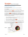
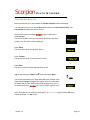
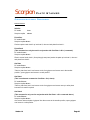
Scorpion Plate Stacker
User Manual
Version 1:4
Scorpion Plate Stacker
Contents
Introduction
3
Caution Notes
4-5
Before using the Scorpion
6
Positioning
7
Connecting the Mains Supply
Electrical
8
Air
9
Integration with External devices
Optimisation
10
Switching Dual Mode Operation
11
Connecting the Supplies
12
Connecting the Control Pod
13
Controlled Stop
14
Transfer Set-up
15 - 16
Advanced Set-up
17
Gripper Set-up
18
Hotel Set-up
19 – 20
Additional Set-up
21
Communication Protocol
22 - 29
Service & Maintenance
TBC
Helpful Hints
31 - 32
CE Certification
33 - 34
Contact Information
35
Version 1:4
Page 2
Scorpion Plate Stacker
Introduction
The Scorpion Plate Stacker has been specifically created as an automated high throughput
plate handling system to integrate with most stand-alone laboratory automation equipment. The
system is designed to be an entry level automation system with the same basic functions as
many larger systems with the capability of addition and expansion to handle different types of
media.
Specification
Size:
620mm x 230mm (305mm at front) x 900mm (LxWxH)
Capacity:
2 Hotels @ 680mm high capacity. 1 full, 1 transfer.
72-off 384 well PCR Plates i.e. ABgene TF-0384
54-off 96 well PCR Plates i.e. ABgene AB-0800
40-off 96/384/Dish Media Plates i.e. Nunc 167008
Transfer
Total time inc. 7 second Chameleon sealing sequence = 20 seconds max.
Times:
Therefore, 24 minutes for 72-384 well plate cycle or 18 minutes for 54-96 well
plate cycle.
Integration
The Scorpion can be integrated with the following External Devices. If your product is not on the
list, consult your Distributor or KBiosystems for further assistance.
•
•
ALPS3000™
ALPS300™
•
Chameleon
•
•
KAPS 500
External PC as Slave Device
Options
•
•
•
•
•
Left Handed Version
Lidded Plate Hotels
Lid Handling
Barcode Reading
Gripper Arm options for different plates
Version 1:4
Page 3
Scorpion Plate Stacker
Caution Notes
It is Important that the Scorpion is installed and operated in such a way that all applicable Heath
and Safety requirements are met. It is the users responsibility to ensure that all relevant Health
and Safety Regulations are identified and complied with. Failure to do so, may result in damage
to the equipment and could cause personal injury. In particular, the user should study the
contents of this guide carefully before handling or operating this equipment.
All users should be fully trained and have a full operational knowledge of the equipment.
Under No circumstances will the supplier of this equipment be liable for any incidental,
consequential or special damages of any kind whatsoever, including but not limited to lost profits
arising from, or in anyway connected with the use of this equipment or this instruction manual.
WARNING SYMBOLS In accordance with IEC 417
Risk of Electric Shock
Moving Equipment
!
Machinery May Move Without Warning
!
Earth Protective Conductor
I-0
Mains Switch Symbols
I = ON
Version 1:4
0 = OFF
Page 4
Scorpion Plate Stacker
Caution Notes
Statement:
Warning:
Do not operate this instrument in an atmosphere containing explosive gases.
Statement:
Warning:
Only approved, supplied mains cord set must be used with this instrument.
Statement:
Warning:
If it is required to use an extension lead, the lead MUST be earthed & tested
independently before use with KBiosystems equipment.
Statement:
Voltage:
The Scorpion is supplied with an external power supply for direct connection to
normal 100V-240V AC supply @ 50/60Hz, with an output of 24V DC, 2.5A & 60W.
•
If supplied, safety guards MUST be used at ALL times during the operation of the unit.
•
The unit should only be used in a suitably ventilated area. The use of solvents on the unit
is not recommended.
•
Certain components move during the correct operation of the equipment and due care
should be taken to avoid personal injury.
•
The Electrical Supply disconnected, prior to the removal of any safety guards.
•
KBiosystems Limited accepts no responsibility for the misuse of this equipment.
The Mains Plug supplied with the Scorpion stacker, is fitted with the following fuse: Supply
230V
Fuses Fitted in Plug
Mains IEC UK Only
13 Ampere
Fuses Fitted in Platform
T5AH 250V
Only refit the correct type of Fuse.
The Scorpion stacker should be operated in an environment with a temperature range of 15°C 40°C and a non-condensing relative humidity range of 10% - 80%
Version 1:4
Page 5
Scorpion Plate Stacker
Before Using the Scorpion
When unpacking your Scorpion Plate Stacker, visually inspect the unit for any damage
which may have occurred during shipping. Do not use the unit if any damage is present.
Check that all components are present. See packing list below.
Before removing the unit from the packaging, ensure there is a bench with a mains supply and
compressed air outlet within 2M.
To remove the unit, first cut both straps from around the case release the clips by rotating them
through 90° and fold back the lid. Remove any additional components. Next remove central
packaging from the arm of the unit and once all this packaging is clear remove from the case.
The unit is supplied in a re-useable shipping container that must be retained in case the unit
needs to be returned for servicing. All shipping case material should be retained in case of future
shipment. KBiosystems Limited accepts no responsibility for any damage incurred during return
shipping unless the unit is packed in the same packaging as it was delivered.
Note - This equipment must be lifted in accordance with EC directive.
Packing/Contents Listing
Scorpion Plate Stacker
Standard Integration Plate
2x Hotels
2x Hotel Inserts
LCD Control Pod
24V dc Power Supply
Mains IEC Lead UK
Mains IEC Lead USA
Mains IEC Lead EU
RS232 Extension Lead 1
RS232 Communications Lead
6mm Push-In Air Fitting (Blue)
¼” Push-In Air Fitting (Orange)
Tool Kit
Instruction Manual
Warranty Documentation
Note - If any components from the above list are missing, contact the distributor immediately for
replacement
Version 1:4
Page 6
Scorpion Plate Stacker
Positioning
The Standard Integration Plate accommodates the Scorpion and the most commonly
integrated units, ALPS300™, ALPS3000™ and Chameleon. Integration Plates to suit other
products are available and can be purchased through KBiosystems or your distributor.
When positioning the Scorpion plate stacker, ensure there is sufficient space on a sturdy
bench for movement and accessories. Once the Scorpion is on a bench, ensure that no
shipping material is visible on, in or around the system
1.
Place the Integration Plate onto the bench with the smaller plate upwards, toward the
front of the bench and on the right hand side.
2.
Lift the Scorpion onto the Integration Plate, locating the middle and rear feet of the unit
into the 4 holes in the smaller plate.
3.
Push down on the Scorpion to ensure a good secure fit. Note the feet should still be in
contact with the bench top. Check this by looking at the front feet and making sure the
unit is sitting level.
4.
Position the External Device on the left hand side of the Scorpion, locating the feet into
the holes. The Standard Integration Plate will fit the following devices into the specified
holes.
Holes ‘A’
Holes ‘B’
Version 1:4
ALPS300™
ALPS3000™, Chameleon
Page 7
Scorpion Plate Stacker
Connecting the electrical supply
Note: - The system is self regulated to sense voltage differences between 100 and 240 volts AC.
1.
Remove the external power supply from the packaging, and connect the IEC lead specific
to your location into the IEC connector on the power supply.
2.
Connect the lead to the mains power supply, and if present, switch on.
3.
Check that the Green indicator LED on the top of the power supply is illuminated.
Prior to inserting the DC Connector, ensure the rocker I.O. switch on the Side Control Panel
of the Scorpion is in the Off ‘O’ position.
4.
Insert the DC Connector into the inlet marked 24V DC SUPPLY on the Rear Inlet Panel.
At this time, do NOT switch the rocker I.O. Switch to the On ‘I’ position.
Figure 8.1 –
Rear Inlet Panel
Electrical Supply
Figure 8.2 – Side Control Panel
Version 1:4
Page 8
Scorpion Plate Stacker
Connecting the air supply
U. K. Europe and Asia supplied units.
The unit is supplied with a 6mm push-in connector (Blue) to fit into the ¼” BSP inlet.
U. S. A. supplied units.
The unit is supplied with a ¼” push-in connector (Orange) to fit into the ¼” BSP inlet.
When fitting an air connector to the Scorpion plate stacker always use 2 spanners, one to
tighten the connector and one to prevent the bulkhead fitting from turning. These are 14mm &
17mm respectively. If the bulkhead fitting is allowed to rotate it may become loose.
The air supply for the Scorpion should be 80psi (5.5 bar) and a maximum of 87psi (6 bar).
The supply should be able to provide 50 litres/minute through a pressure regulator as there is
no regulation of the air within the unit. Exceeding the maximum pressure may damage the unit.
The air supplied must be clean, dry and oil-free. Most air regulators include a water filter but not
an oil filter; this may need to be fitted separately.
1.
Fit the required air fitting to the bulkhead fitting on the Rear Inlet Panel. Ensure that this
is tight as an air leak will affect the operating of the unit.
2.
Connect a length of 6mm or ¼” polyurethane tubing, of no smaller internal bore of
4mm, and of no greater length than 2M, to the Scorpion.
3.
Connect the other end to the main supply, and if present, open the stop valve or similar.
Note - If the mains supply is greater than 87psi (6 bar), then fit a pressure regulator in-line. This
will have to be tested and set prior to connecting the Scorpion to the main supply as pressure
exceeding this may cause damage to the unit.
Figure 9.1 –
Version 1:4
Rear Inlet Panel
Air Supply
Page 9
Scorpion Plate Stacker
Integration with External Devices
When connecting to an external device, there are two ways in which the Scorpion can operate
with the device, as the master or as a slave. Below is a description of each method of operation
and the type of devices that each method is applicable to.
Stand-Alone Mode The Scorpion will take control of the external device, operating basic
commands such as ‘SEAL’ if used with an automated plate sealer. This master
control allows the Scorpion to streamline the procedure dependant on the amount
of plates in the hotels (variable) and the cycle parameters and ready status of the
external device. The unit will operate as a simple set-up and walk away integration
and cycle until there are no plates left in the hotel. LCD Control Pod required.
•
Default Mode
•
Compatible Devices -
ALPS300™, ALPS3000™, Chameleon, ASP50, KAPS 500
Integrated Mode The Scorpion will act as a slave device to a master controller, typically
a PC connecting and operating multiple slave devices or the controller of a
complex robotic platform. The Master controller will set when the Scorpion
presents a plate to the system and the parameters of operation i.e. type & quantity
of plates. This type of operation usually requires more in depth set-up from the
user. No LCD Control Pod required.
•
Compatible Devices -
K6 BiOcto-Pic, Fusion, Thermo Multidrop
Integration Mode 0 Integration Mode 1 Integration Mode 2 -
For use with non-lidded plates
For use with lidded plates (no de-lidding by Scorpion)
For use with lidded plates with de-lidding by Scorpion
Supplied with the Scorpion are two communication leads, marked Extension Lead 1 & a
Standard RS232 Lead. These are for use with different devices in Master or Slave operation,
depending on the communication protocol of the External Device. Below is a list of which
devices require which lead, and to which communication port on the Scorpion.
Note – As products are introduced, this list will be updated, however if you’re device is not listed
below, contact your distributor for advice.
Extension Lead 1 (Black)
RS232 Port
-
ALPS300™
ALPS3000™
Chameleon
KAPS 500
Standard Comms Lead (Grey) AUX COMM Port
Version 1:4
External PC in Integration Mode
Page 10
Scorpion Plate Stacker
Switching Dual Mode Operation
Switch Stand-alone to Integration mode
1.
Switch Stacker OFF
2.
Hold the pause button (large red push button on side of main stacker).
3.
Switch Stacker ON
4.
Keep pause button pushed in for approx 3 seconds.
5.
Release pause push button.
When re-powered the stacker LCD module (if connected) will display:scrolling KBiosystems logo, Scorpion logo, Software version, Integrated Mode screen.
Switch Integration to Stand-alone mode
1.
Switch Stacker OFF
2.
Hold the pause button (large red push button on side of main stacker).
3.
Switch Stacker ON
4.
Keep pause button pushed in for approx 3 seconds.
5.
Release pause push button.
When re-powered the stacker LCD module (if connected) will display:scrolling KBiosystems logo, Scorpion logo, Software version, cont-eject-open-reset screen.
How to tell what mode the Stacker is in:Power up with LCD Control Pod attached.
If mode is ‘STAND-ALONE' then LCD will show :scrolling Kbiosystems logo, Scorpion logo, Software version, cont-eject-open-reset screen.
If mode is ‘INTEGRATION' then LCD will show :scrolling Kbiosystems logo, Scorpion logo, Software version, Integrated Mode screen.
Version 1:4
Page 11
Scorpion Plate Stacker
Integration with External Devices
Connecting the Supplies
1.
Connect the required Extension Lead to the correct COMM port on the Rear Inlet Panel
of the Scorpion. Tighten the screw-in fixings to secure the plug.
2.
Connect the other end to the COMM port of the External Device. Note – This is usually
at the rear of the unit. Contact the manufacturer for further assistance if problems arise.
Version 1:4
Figure 11.1 –
Rear Inlet Panel
RS232 COMM Port
Figure 11.2 –
Rear Inlet Panel
AUX COMM Port
Page 12
Scorpion Plate Stacker
Connecting the Control Pod
The Control Pod is for use with the Scorpion plate stacker when integrating with an
external device that will act as the slave unit i.e. the Scorpion will control when the external
device operates but with the parameters remaining locally set.
Note - The Control Pod is not used when the Scorpion is the Slave to an external device such
as a PC Controlled BiOcto-Pic. Refer to the User Manual for the external device for setting
and operating the Scorpion.
When connecting the Control Pod to the Scorpion plate stacker always ensure the unit is
switched OFF.
1.
Place the Control Pod next to the Scorpion in close proximity to the Side Control
Panel.
2.
Connect the 6-Pin plug into the mating socket on the Side Control Panel. Note - This
has a location tab on the inside to ensure correct orientation.
3.
Secure the Plug to Socket using the screw collar.
Figure 1.5 –
Control Pod Connection
Note - The Control Pod utilises touch screen technology which is susceptible to damage if
operated in a moist environment or with wet fingers. Ensure when operating the device that
fingers are dry and that the unit is regularly cleaned with a dry cloth.
Version 1:4
Page 13
Scorpion Plate Stacker
Controlled Stop
The Red Push Button on the Scorpion plate stacker Side Control Panel acts as a
Category 2 controlled stop as described and in accordance with BSEN 60204 Safety of
Machinery Directive section 9.2.2 Stop Functions. This is NOT to be used as an Emergency
Stop button in cases of collision or entrapment.
For cases requiring an immediate stop and
disconnection of power supply, the Rocker I.O.
switch located below the pushbutton should be
switched to the ‘O’ position, but this is only
recommended in the most extreme cases.
Figure 1.5 –
Controlled Stop
Pushbutton
The Scorpion has preventative measures inbuilt to remove any danger of entrapment of body
parts in the moving arm or possible damage to an external device, and therefore the use of the
Controlled Stop is seldom required. In cases of collision with an external device or entrapment
of body parts in the moving axis of the Scorpion, the Controlled Stop can be pushed to
immediately stop the axis from moving, however power will remain on the unit with the drives in
an energised state. In this state, if a MTP is being held in the gripper arms, to prevent possible
spillage of sample, the MTP will remain gripped until instruction form the user to release.
Ensure the Scorpion transfer bed is clear of obstructions.
The ‘Open Stacker Gripper’ screen is displayed.
If a plate is present in the gripper arms, press Yes.
The unit will release the plate and display the ‘Initialise’ screen.
No
Yes
Press Proceed.
The unit will reset the drives.
At this point, check the Scorpion transfer bed is clear from obstructions
Proceed
as the hotel may have been in the process of releasing a plate.
To continue the run from that point, Press Run.
The unit will continue to Run in normal operation.
Run
Version 1:4
Page 14
Scorpion Plate Stacker
Transfer Set-up
Before commencing a run, the software set Transfer Position needs to be defined.
Turn the power on to the unit with the Rocker I.O. switch on the Side Control Panel. The
Control Pod will display the Initialise screen.
Ensure that the area around the Scorpion is clear of obstructions.
Press Proceed.
The unit will initialise, moving the arm and lift platforms to the home
position. The ‘Run’ Screen will be displayed.
Proceed
Press Setup.
This will proceed to the ‘Setup Menu’ screen.
Setup
Press Transfer.
This will proceed to the ‘Transfer Position’ screen.
Transfer
Press Enter.
This will move the arm to the default position of 100.
Enter
Jog the arm using the up▲& down▼ arrows and press Enter.
The screen reverts back to the Setup Menu after each Transfer move.
Repeat steps Transfer & Jog until the gripper arms are central about
the shuttle and the same distance above the shuttle as they were to
the transfer bed of the Scorpion in the ‘home’ position (approx 2mm).
▲
▼ 128
Enter
Note - For reference, the setting for ALPS3000™ & Chameleon is approximately 128 counts
and the ALPS300 ™ is 230 counts.
Version 1:4
Page 15
Scorpion Plate Stacker
Transfer Set-up - Adjustment
The Integration Plate as described on page 7 allows for the Scorpion to be adjusted in a lateral
direction to meet with the external device. The Red section of the plate that locates the Scorpion
feet slides on the main plate, locking in position with two fixing screws.
With the External Device plate shuttle/bed in the load position, and the Scorpion Powered ON
and in the Transfer Position as set-up on page 14;
1.
Loosen the two fixing screws on the right hand side of the Integration Plate using the
4mm Allen Key supplied.
2.
Move the Scorpion left or right, locating the gripper arms centrally over the external
device shuttle/bed.
3.
Tighten the two fixing screws.
For Additional Setting instructions for the transfer position, see page 20.
Version 1:4
Page 16
Scorpion Plate Stacker
Advanced Set-up
Before commencing a run, the software set Advanced Settings need to be defined. This
includes the plate Drop Position and the External Device setup.
Press Setup.
This will proceed to the Setup Menu screen.
Press Advance.
This displays the Drop Position Screen. This sets the amount of counts
the lift platform drops before releasing the hotel lock to remove a plate.
Using the up▲& down▼ arrows, adjust this to the desired height.
For reference, most 20μl 384 well plates will be 120, most 96 well
plates will be 160. Approx. count value is 10 counts for a 1mm
increase in skirt height Dim ‘A’ (See Fig1.12)
Once this is set, press Enter.
The screen proceeds to the External Device setup screen.
If using with an ALPS300™, select ‘Yes’ by toggling through using the
up▲& down▼ arrows. If using another external device, leave at the
default ‘No’.
Press Enter.
The unit then displays the Run screen.
Figure 1.12 –
Version 1:4
Setup
adv.
▲
▼ 120
Enter
▲ ALPS 300
▼ No
Enter
Plate Skirt Dimension
Page 17
Scorpion Plate Stacker
Gripper Set-up
The Gripper Arms on the Scorpion plate stacker are manually adjustable to set the
position the plate is gripped and to prevent over-gripping and therefore deforming flexible plates
such as vacuum formed polystyrene plates.
This should be performed when in the OFF state, where the gripper arms are in a closed
position and the arm can be moved. Ensure there is an air supply to the unit.
Height Set-up
1.
Place a plate on the Scorpion transfer bed in the transfer position.
2.
Look across the transfer position to check if
the top of the gripper arms are approximately in
line with the top of the plate. If not, then
3.
Remove the 2 fixing screws in the Gripper
arm using the 2.5mm Allen Key supplied, and
move the arm to one of the positions closer
to the required height.
4.
Replace the fixing screws. Ensure the arms are set at the same height and are level.
Width Adjustment
Note – This will not need to be
Adjusted for rigid plates.
1.
Turn the Adjuster Knob clockwise
until it reaches it’s limit (approx 2 turns).
2.
Place a plate on the the Scorpion transfer
bed in the transfer position.
3.
Turn the Adjuster Knob anti-clockwise. The gripper
arms will move in to grip the plate. Continue adjusting
until all four pins are in contact with the side of the plate
and until the plate starts to deform.
Version 1:4
Page 18
Scorpion Plate Stacker
Hotel Set-up
Once you have followed the previous steps, carry out the following steps to set-up the hotels with
the MTP’s to be used. The majority of MTP’s work with the stacks in the default set-up position,
however it is good practice to check this before commencing the first run.
1.
Place the Hotel stack onto a clear bench.
2.
Ensure that the adjustment knobs are in the
default position with the red dot facing into
the hotel.
3.
Lay the hotel stack down with the base
accessible on the end of the bench.
4.
Insert a new plate into the hotel stack
with the underside of the plate facing
towards the bottom.
5.
Ensure that the plate is prevented from
passing through the stack by the
retractable grippers.
Note - If the plate passes through, check again that the adjustment knobs are facing in. If the
plate is still allowed to pass through, you may be using an unsupported plate type and you
should contact the distributor for further advice.
6.
Remove the plate from the stack and re-insert with the
top-side (well opening) facing towards the bottom.
7.
Ensure the top of the plate, the section above the skirt, is
not gripped by the retractable grippers and moves freely.
8.
If the plate does not move freely, rotate the adjustment
knobs either clockwise or counter-clockwise in equal
amounts so that there is clearance on the sides of the plate.
Version 1:4
Page 19
Scorpion Plate Stacker
Hotel Set-up
The hotels are now set-up for the plate type. These can now be loaded onto the Scorpion in the
positions shown on the side cover, with the full hotel (Source) at the rear and the empty hotel
(Destination) at the front. Ensure that the hotel lock is applied before commencing a run.
Source - Full
Destination - Empty
With the plates loaded into the Source Hotel, insert the Plate Weights on to the top plate in the
Source, and into the bottom of the Destination Hotel. These prevent the plates from tipping when
being inserted back into the hotel, and to ensure light plates are ejected from the hotel. They will
not pass through the hotel locks during normal operation and will therefore not affect the run.
Version 1:4
Page 20
Scorpion Plate Stacker
Additional Set-up
The Transfer Bed on the Scorpion plate stacker has manually adjustable guides to set the
position the plate is presented to the griper arms and subsequently to the external device. These
adjustments are usually required after initially running the unit, where the plate transfer position
may need to be altered.
This should be performed when in the OFF state, where the gripper arms are in a closed
position and the arm can be moved. Move the arm to a safe position away from the transfer bed.
Plate Stop
If the plate is contacting with either front or back of the external device plate shuttle.
1.
Loosen, but do not remove, the 2 fixing screws on the Plate Stop using the 2.5mm Allen
Key supplied.
2.
Move the Plate Stop on the slotted holes to suit the required position i.e. forwards if plate
colliding with the front of the shuttle (nearest user) or backwards for vice-versa
adjustment.
3.
Tighten the 2 fixing screws.
Width Adjustment
Note – It is unlikely that this will need to be adjusted for any reason, but if required;
1.
Loosen, but do not remove, the fixing screws on the Plate Guides using the 2.5mm
Allen Key supplied.
2.
Move the Plate Guides on the slotted holes to suit the required position i.e. inwards if
plate is allowed to rotate or outwards if the plate is gripped too tight. It is recommended
that there is approximately 1mm of movement on both sides of the plate.
3.
Tighten the fixing screws.
Version 1:4
Page 21
Scorpion Plate Stacker
Communications Protocol
Serial Port Setup
Baud rate
9600
Data bits
8
Parity
None
Stop bits
1
Flow control
None
All communications via ASCII.
Connection is via a straight cable – not a modem cable.
PC (9 way female)
Scorpion (9 way female)
Pin 2 <---------------------------------> Pin 2
Pin 3 <---------------------------------> Pin 3
Pin 5<----------------------------------> Pin 5
The unit responds to each message within 100 msec.
Status Message
PC sends
?<cr>
Scorpion replies: <status byte><cr>
the status byte is a hexadecimal value represented in ASCII, i.e. the characters "ff" means 0xff
hex.
Scorpion replies: err<cr>
Response to any incorrect / invalid commands
Bit values:
bit 1 error
bit 2 busy
bit 4 restacking
bit 5 finished stack run (init command needed to reset this bit)
When checking the communication using, for example Hyper-terminal, the responses to the
status message enquiry are hexadecimal values which when converted to binary values allow
the status to be interpreted. For example, when the unit is busy, the response is 04. In binary this
is 00000100.
NOTE:- <cr> = carriage return.
NOTE:- Hotel 1 refers to the plate stacker hotel furthest from the gripping arm.
NOTE:- Hotel 2 refers to the plate stacker hotel nearest to the gripping arm.
Version 1:4
Page 22
Scorpion Plate Stacker
Communications Protocol
Commands
Initialise
PC sends
Scorpion replies
I<cr>
ok<cr>
Finish Run
PC sends C<cr>
Scorpion replies ok<cr>
Pushes a plate under hotel 2 up into hotel 2, does not take plate from hotel 1.
Finish Run2
(This command can only be used in conjunction with ‘Get Plate 1 <G1>)’ command).
PC sends C1<cr>
Scorpion replies ok<cr>
Plate is moved under hotel 1 (from plate grip area) and pushes the plate up into hotel 1, does not
take plate from hotel 2.
Get Plate
PC sends G<cr>
Scorpion replies ok<cr>
Take’s a plate from hotel 1 and moves to the front grippers and moves arm to the transfer
position., opens grippers and moves to a safe position.
Get Plate 1
(This is an alternate command to ‘Get Plate <G>)’ above).
PC sends G1<cr>
Scorpion replies ok<cr>
Take’s a plate from hotel 1 and moves to the front grippers and moves arm up to allow plate
barcode to be read if required.
Get Plate 2
(This command is only used in conjunction with ‘Get Plate 1 <G1>’ command above).
PC sends G2<cr>
Scorpion replies ok<cr>
Arm moves down and plate is gripped. Arm then moves to the transfer position, opens grippers
and moves to a safe position.
Version 1:3
1:4
Page 23
Scorpion Plate Stacker
Communications Protocol
Get Plate 3
PC sends G3<cr>
Scorpion replies ok<cr>
Take’s a plate from hotel 1(default) and moves to the front grippers, arm moves down and plate is
gripped. Arm then moves to the transfer position, opens grippers and arm moves back to home
position.
Get Plate 3 (Hotel 1).
PC sends G3H1<cr>
Scorpion replies ok<cr>
Take’s a plate from hotel 1 and moves to the front grippers, arm moves down and plate is
gripped. Arm then moves to the transfer position, opens grippers and arm moves back to home
position.
Get Plate 3 (Hotel 2).
PC sends G3H2<cr>
Scorpion replies ok<cr>
Take’s a plate from hotel 2 and moves to the front grippers, arm moves down and plate is
gripped. Arm then moves to the transfer position, opens grippers and arm moves back to home
position.
Get Plate 4
PC sends G4<cr>
Scorpion replies ok<cr>
Take’s a plate from hotel 1 and moves to the front grippers and moves arm to the transfer
position. The plate is not lowered on to target
Get Plate 5
PC sends G5<cr>
Scorpion replies ok<cr>
Arm lowers and the gripper opens placing plate on target, arm then moves to a safe position.
Version 1:3
1:4
Page 24
Scorpion Plate Stacker
Communications Protocol
Replace Plate
PC sends R<cr>
Scorpion replies ok<cr>
Take’s the plate from the external device and moves it to under hotel 2 on the transfer belt. The
user then sends a new G command which moves the plate up into hotel 2 and removes a new
plate from hotel 1. The G & R commands continue until all plates have been sealed and the
status bit 5 is set to signal no more plates in hotel 1.
Replace Plate 3
PC sends R3<cr>
Scorpion replies ok<cr>
Arm moves from home position to external device and takes the plate from the external device,
the arm then returns to the home position and plate is placed in hotel 2(default) .
Replace Plate 3 (Hotel 1)
PC sends R3H1<cr>
Scorpion replies ok<cr>
Arm moves from home position to external device and takes the plate from the external device,
the arm then returns to the home position and plate is placed in hotel 1.
Replace Plate 3 (Hotel2)
PC sends R3H2<cr>
Scorpion replies ok<cr>
Arm moves from home position to external device and takes the plate from the external device,
the arm then returns to the home position and plate is placed in hotel 2.
Replace Plate 4
PC sends R4<cr>
Scorpion replies ok<cr>
Take’s the plate from the external device and arm moves up.
Replace Plate 5
PC sends R5<cr>
Scorpion replies ok<cr>
Arm moves to home position and moves plate under hotel 2 on the transfer belt. The user then
sends a new G’s command which moves the plate up into hotel 2 and removes a new plate from
hotel 1. The G’s & R’s commands continue until all plates have been sealed and
the status bit 5 is set to signal no more plates in hotel 1.
Version 1:3
1:4
Page 25
Scorpion Plate Stacker
Communications Protocol
Restack Hotels
PC sends S<cr>
Scorpion replies ok<cr>
The plate will restack from the Destination Hotel to the Source Hotel in the same order they were
loaded, until there are no plates remaining.
Error Message
PC sends E<cr>
Scorpion replies E##<cr>
Where ## is a decimal value represented in ASCII, i.e. the characters "03" means ‘arm up error’.
Error numbers:
3
Arm up error
4
Arm down error
6
Plate transfer back error
7
Arm home error
8
Lift home error
9
Conveyor jam
10
Pause button was pressed
Set transfer position.
PC sends P1=???<cr>
// Where ??? is the transfer position value 0 to 255.
Scorpion replies: ok<cr>
Read transfer position.
PC sends P1<cr>
Scorpion replies: P1=???<cr>
// Where ??? is the transfer position value 0 to 255.
Test transfer position.
PC sends T<cr>
Scorpion replies: ok<cr>
// The arm moves to the transfer position for the external device.
Version 1:3
1:4
Page 26
Scorpion Plate Stacker
Communications Protocol
Jog to Target
PC sends J1<cr>
Scorpion replies ok<cr>
Arm is jogged 1 transfer increment to the target. This command only works after a ‘G4’ command
or a ‘T’ command. If the transfer position is already at the maximum (255) then the command will
return ‘err<cr>’
Jog to Home
PC sends J2<cr>
Scorpion replies ok<cr>
Arm is jogged 1 transfer increment to the home. This command only works after a ‘G4’ command
or a ‘T’ command. If the transfer position is already at the minimum (0) then the command will
return ‘err<cr>’
Adjust Drop position
Pc sends P3=***<cr> // Where ??? is the transfer position value 0 to 250 (Default 44).
Scorpion replies P3***ok<cr>
The lift moves up into the hotel to lift the plate. The hotel gripper is opened at this stage. The lift
then moves down by the drop position, the greater the drop position, the longer the hotel gripper
is open. The lift moves to the top position minus the drop position then fires the hotel gripper in
which holds the remaining plates in the hotel. The lift then moves to the bottom position and the
plate is taken by the transfer conveyor.
Set arm safe position.
PC sends P4=???<cr>
// Where ??? is the transfer position value 0 to 255 (Default 50).
Scorpion replies: ok<cr>
Read arm safe position.
PC sends P4<cr>
Scorpion replies: P4=???<cr>
// Where ??? is the transfer position value 0 to 255.
Version 1:3
1:4
Page 27
Scorpion Plate Stacker
Communications Protocol
Set arm speed.
PC sends P5=???<cr>
// Where ??? is the speed setting value 1 to 100 (Default 100)
Scorpion replies: ok<cr>
// represents percent, where 100 is maximum speed and 1 is 1% of maximum speed.
Read arm speed.
PC sends P5<cr>
Scorpion replies: P4=???<cr>
// Where ??? is the speed setting value 1 to 100.
Check Firmware Version
Pc sends V<cr>
Scorpion replies Scorpion V?.?? (where ?.?? is the firmware version number).
Set Mode
Pc sends M?<cr>
// Where ? is the mode value,
// 0 = Non lidded plates,
// 1 = Lidded plates.
// 2 = Lidded plates / de-lidding.
Scorpion replies ok<cr>
// The Stacker will prime the stacks after mode 1 or mode 2 has been set.
// The Stacker will initialize after mode 0 has been set. All the above listed
// commands can be used.
// The following commands can currently be used in mode 1 and mode 2:// I,G,R,S,T,J1,J2,E,P1.P3,P4,P5,M
Read Mode
Pc sends M<cr>
Scorpion replies: ?<cr>
// Where ? is the mode set,
// returns 0 for non lidded plate
// returns 1 for lidded plates
// returns 2 for lidded plates (with de-lidding)
Version 1:3
1:4
Page 28
Scorpion Plate Stacker
Communications Protocol
Switching Outputs via comms
Pc sends
Scorpion replies
K*=1<cr>
OK<cr>
(where * is the output number)
Example:
Pc sends
Scorpion replies
K1=1<cr>
OK<cr>
(SWITCHES OUTPUT 1 ON)
Pc sends
Scorpion replies
K1=0<cr>
OK<cr>
(SWITCHES OUTPUT 1 OFF)
Output listing:
Output 1 =
Output 4 =
Output 5 =
Output 6 =
Output 7 =
Output 9 =
Conveyor on forward direction
Hotel 2 gripper open/close
Hotel 2 gripper open/close
Gripper Arm up/down
Conveyor on reverse direction
Gripper open/close
Version 1:4
Page 29
Scorpion Plate Stacker
Helpful Hints
Calculating the drop position
Non-Lidded Plates
To calculate the drop position parameter in millimeters (0.1 resolution):Measure the thickness of the ‘skirt’ of the plate (note you may still need to adjust this figure
up/down).
Example:- If the measurement is 12.5 mm the plate drop value is 125.
Generally use the above procedure to obtain a ‘rough’ setting and then adjust figure accordingly
when you do initial tests with the actual plates
If the plates do not eject properly from a hotel then increase the drop position parameter.
If more than one plate is ejected from a hotel then decrease the drop position parameter.
Lidded Plates
To calculate the drop position parameter in millimeters (0.1 resolution):Measure from the top of the lid to half way across the skirt of the plate (note you may still need to
adjust this figure up/down
Example:- If the measurement is 15.0 mm the plate drop value is 150.
Generally use the above procedure to obtain a ‘rough’ setting and then adjust figure accordingly
when you do initial tests with the actual plates.
If the plate or lid (normally the lid) do not eject from the hotel then increase the drop position
parameter. If more then one plate / lid is ejected form the hotel then decrease the drop position
parameter.
PLEASE NOTE YOU MAY DAMAGE THE ODD PLATE / LID IN THE PROCESS OF SETTING
UP.
Version 1:4
Page 30
Scorpion Plate Stacker
Helpful Hints
Calculating the drop position
Non-Lidded Plates
To calculate the drop position parameter in millimeters (0.1 resolution):Measure the thickness of the ‘skirt’ of the plate (note you may still need to adjust this figure
up/down).
Example:- If the measurement is 12.5 mm the plate drop value is 125.
Generally use the above procedure to obtain a ‘rough’ setting and then adjust figure accordingly
when you do initial tests with the actual plates
If the plates do not eject properly from a hotel then increase the drop position parameter.
If more than one plate is ejected from a hotel then decrease the drop position parameter.
Lidded Plates
To calculate the drop position parameter in millimeters (0.1 resolution):Measure from the top of the lid to half way across the skirt of the plate (note you may still need to
adjust this figure up/down
Example:- If the measurement is 15.0 mm the plate drop value is 150.
Generally use the above procedure to obtain a ‘rough’ setting and then adjust figure accordingly
when you do initial tests with the actual plates.
If the plate or lid (normally the lid) do not eject from the hotel then increase the drop position
parameter. If more then one plate / lid is ejected form the hotel then decrease the drop position
parameter.
PLEASE NOTE YOU MAY DAMAGE THE ODD PLATE / LID IN THE PROCESS OF SETTING
UP.
Version 1:4
Page 31
Scorpion Plate Stacker
Helpful Hints
Integration Example
The ‘ok’ response from the Stacker is only acknowledgement of a valid command, i.e. the
command sent to the Stacker was validated and has been accepted. It has does not indicate
when a task has completed.
You can use the ‘?<cr>’ (status) command to determine if a task has completed.
The rs232 communication on the Stacker is disabled during a task, only when a task is
completed
and the Stacker is idle will the rs232 communication be restored.
So during a task you will receive no response from the Stacker.
At the end of a task you will receive the status byte (if you send ‘?<cr>’.
This method is preferred because if there is an error during a task, the Stacker status response
will reflect that.
Example:Send command :- ‘G<cr>’
Wait 100ms
Was ‘ok’<cr> received? -> no then resend command.
Yes:- go to loop1.
Loop1
Wait 100ms
Send ‘?<cr>’
Was there a response? -> no then go to loop1.
Yes:Was response ‘00<cr>’ -> yes then task completed with no errors.
No:Was response ‘02<cr>’ -> yes then get error i.e. send ‘E<cr>’.
Else:- process other status bits.
Version 1:4
Page 32
Scorpion Plate Stacker
EC Declaration of Conformity
i.
As detailed under the European Machinery Directive 89/392/EEC (amended by
91/368/EEC) and under the UK legislation. The supply of Machinery (Safety) Regulations
1992 (SI 1992/3073).
ii.
As detailed under The Electromagnetic Compatibility Directive 89/336/EEC (amended by
91/263/EEC and 92/31/EEC and the UK legislation, the Electromagnetic Compatibility
Regulations 1992.
As detailed under The European Low Voltage Directive 73/23/EEC (amended by 93/68/EEC)
and the UK legislation, The Electrical Equipment (Safety) Regulations 1994.
The Declaration of Conformity is provided for the following equipment:Equipment
Scorpion Plate Stacker
Serial Number
To be included
Supplier into the EU
KBiosystems Limited
Units 5 to 10
Paycocke Close
Basildon
Essex
SS14 3HS
Transposed Harmonised Standards
BSEN 12100-1 Safety machines: concepts
General: principles for design; basic terminology& methodology
BSEN 12100-2 Safety of machines: basic concepts, general principles
for design; technical principles
BSEN 61010 Safety requirements for electrical Equipment for
measurement, control & laboratory use
BSEN 60204 safety of Machinery; electrical equipment of machines
(section 19)
BSEN 50081-2 Electromagnetic Compatibility; generic emission
standard, industrial environment
BSEN 61000-6-2 Electromagnetic compatibility (EMC) Generic
standard, immunity for industrial environments
Other Standards
BS5378 safety signs & colours
Version 1:4
Page 33
Scorpion Plate Stacker
EC Declaration of Conformity
Name & Address of the Responsible Person within the EU
Name:
Alan Shepherd
Address:
KBiosystems Limited
Units 5 to 10
Paycocke Close
Basildon
Essex
SS14 3HS
Signature of the Responsible Person (or Person Empowered to Sign On his behalf)
Signature
Name
Date
Version 1:4
Page 34
Scorpion Plate Stacker
Contact Information
United Kingdom & Europe
FLUIDX Limited
Chelford Road
Nether Alderley
CHESHIRE
SK10 4SY
United Kingdom
Web:
[email protected]
www.fluidx.co.uk
The information in this user guide including any apparatus, Methods, Techniques and Concepts
described herein, are the property of KBiosystems Limited or its Licensees and may not be copied,
disclosed or used for any purpose not expressly authorised by the owners there of.
Since KBiosystems Limited constantly strives to improve all of its products, we reserve the right to
modify equipment and any user instruction manual without prior notice.
No part of this instruction manual may be reproduced in any form without the prior consent of
KBiosystems Limited.
Copyright: KBiosystems Limited 2007
All Rights Reserved
Version 1:4
Page 35
Scorpion Plate Stacker
Notes
Version 1:4
Page 36
Scorpion Plate Stacker
Notes
Version 1:4
Page 37