1
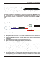
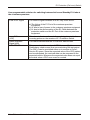
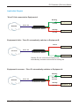
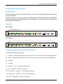
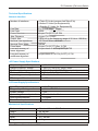
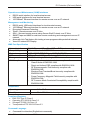
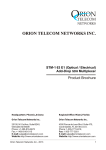
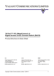
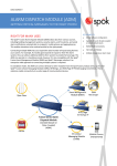
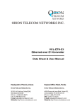
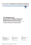
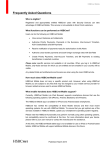
RION TELECOM NETWORKS ORION TELECOM NETWORKS INC. E1 Protection (Fail-Over) Switch Data Sheet & Product Brochure Headquarters: Phoenix, Arizona Regional Office: Miami, Florida Orion Telecom Networks Inc. Orion Telecom Networks Inc. 20100, N 51st Ave, Suite B240, Glendale AZ 85308 Phone: +1 480-816-8672 Fax: +1 480-816-0115 E-mail: [email protected] Website: http://www.oriontelecom.com 4000 Ponce de Leon Blvd. Suite 470, Coral Gables, FL 33146 U.S.A. Phone: 1-305-777-0419, Fax: 1-305-777-0201 E-mail: [email protected] Website: http://www.oriontelecom.com Orion Telecom Networks Inc. - 2012 1 E1 Protection (Fail-over) Switch INDEX S. No. Particulars Pg. No. 1. Product Overview 3 2. Features and Benefits 3 3. Application Diagram 5 4. Front View 6 5. Technical Specifications 7 6. Ordering Information 9 7. Support 10 CAUTION ELECTROSTATIC SENSITIVE DEVICES DO NOT OPEN OR HANDLE EXCEPT AT A STATIC-FREE WORKSTATION Orion Telecom Networks Inc. - 2012 2 E1 Protection (Fail-over) Switch Product Overview Orion 12 Port (4 E1 Links) E1 Protection (FailOver) Switch allows the user to connect upto four E1 lines from the telephone company to "active", as well as to "standby" terminal(s), such as data server(s) etc. at the customer premises. E1 Protection (Fail-Over) Switch In the event of the failure of the data server(s) / equipment connected to the "A / active" ports, the E1 Protection (Fail-Over) Switch shall automatically switch and connect the E1 line (s) from the telephone company to the data server(s) / equipment connected to "B / standby" ports. This ensures minimum downtime-that would have otherwise occurred due to equipment failure. Application Diagram Working Equipment - A E1 Link Network Telco - E1 E1 Protection Switch Standby Equipment - B E1 Link Features and Benefits ! Allows the users to connect upto 4 E1 lines from the Telephone Company to four active and four standby E1 terminals ! User configurable. May be used for a single E1 link and scaled upto 4 E1 links though user configuration ! Independent, user configurable switching parameters for each E1 link ! Built-in real-time clock / real-time logging maintains a history of all events ! Remotely accessible over a TCP-IP networks. Allows the user to access and carry out maintenance, or and E1 switch the links remotely, if required ! Allows the users to create and maintain active/standby/duplicate customer premises data networks/data servers, without requiring to bear the recurring $$$ expense of leasing additional expensive E1s lines from the telephone company ! Automatically switches the E1 link(s) from the Telephone Company between the "active" and "standby" E1 equipment at the customer premises, according to the customer-defined criterion ! Improves security. Allows the user to co-locate the "backup"/" standby" equipment in a different room/building and prevent data loss ! User programmable switching criterion independent for each E1 link ! Increases the reliability of the customer data/IT networks without the recurring additional cost of leasing additional E1 lines from the telephone company. The equipment may be used to create secondary/backup systems at the customer premises to provide virtually uninterrupted service. Orion Telecom Networks Inc. - 2012 3 E1 Protection (Fail-over) Switch User programmable criterion for switching between Active and Standby E1 Links at the customers premises: Loss Of E1 Signal The Loss of Signal condition in an E1 may occur due to: a) The failure of the E1 Port of the customer premises Equipment. b) Or due to loss of power to the customer premises equipment. c) Or due to the disconnection of the E1 Cable between the protection switch and the E1 Port of the customer premises equipment. Loss Of Frame (LOF) This alarm indicates unframed all ones being detected in the incoming pulses on the receiver of E1 Protection Switch. Alarm Indication Signal (AIS) This Alarm indicates that the E1 link error has occured. CRC ERROR This parameter is the number of CRC-4 errors (Cyclic Redundancy check errors) that occurred during the test period. The CRC-4 can be monitored either on-in-service or Out-ofService E1 spans. Since the expected value of the CRC pattern can be anticipated, the received data can be compared to the expected results. Whenever the expected value does not equal the actual value a CRC error event is counted. Orion Telecom Networks Inc. - 2012 4 E1 Protection (Fail-over) Switch Application Diagram Telco E1 link connected to Equipment-A Working Equipment - A E1 Link Network Telco - E1 E1 Protection Switch Standby Equipment - B E1 Link Equipment-A fails – Telco E1 automatically switches to Equipment-B Failed Equipment - A Network Telco - E1 E1 Protection Switch Equipment - B Standby E1 Link connected to Equipment-B automatically connects and becomes a working link Equipment-A recovers – Telco E1 automatically switches to Equipment-A Working Equipment - A Network E1 Link recovers Telco - E1 E1 Protection Switch Standby Equipment - B E1 Link Orion Telecom Networks Inc. - 2012 5 E1 Protection (Fail-over) Switch E1 Protection (Fail-Over) Switch Shelf Description The E1 Protection (Fail-Over) Switch is fitted in a 19-inch 1U shelf that provides access to all external interfaces. The E1 interfaces, power input, access and Management Ports (RS232) and 10/100BaseT Ethernet interfaces) are accessible from the front panel. The external alarm extension are accessible at the rear panel. Front View DC Version E1 PROTECTION SWITCH 1 2 3 4 A1 A2 A3 A4 B1 B2 B3 B4 – + TELCO E1 LINKS E1 EQUP - A L1 L2 L3 L4 E1 EQUP - B ETH OAM OAM RESET COM PORT USB PORT L5 L6 L7 L8 - 48VDC INPUT 1 – + PWR - 48VDC INPUT 2 PWR AC Version E1 PROTECTION SWITCH 1 2 3 TELCO E1 LINKS 4 A1 A2 A3 A4 B1 E1 EQUP - A B2 B3 B4 E1 EQUP - B L1 L2 L3 L4 ETH OAM OAM RESET COM PORT USB PORT L5 L6 L7 L8 PWR 7.5V DC INPUT 1 PWR 7.5V DC INPUT 2 E1 Protection (Fail-Over) Switch LED Indications The LEDs indicate the following: L1 - (Green) - Indicates equipment Port A “In Use” for at least one of the four (enabled) links L2 - (Red) - Indicates equipment Port B “In Use” for at least one of the four (enabled) links L3 - Unused L4 - Unused L5 - (Green) + 3.3 V Present in OAM Card L6 ~ L8 - Unused / For factory use only 7.5 V DC Input 1 - (Green) 7.5V DC Input Present 7.5 V DC Input 2 - (Green) 7.5V DC Input Present 7.5V OFF - Indicates no power is connected Orion Telecom Networks Inc. - 2012 6 E1 Protection (Fail-over) Switch Technical Specifications Network Interface Number of Interfaces Line Rate Line Code Frame Structure Jitter Tolerance Output Jitter Nominal Line Impedance Nominal Pulse Width Pulse Mask Loss and recovery of frame alignment Loss and recovery of multiframe alignment 4 Telco E1 Links (common link/Telco E1s) 4 Active E1 Links (for Equipment-A) 4 Standby E1 Links (for Equipment-B) E1 - 2.048 Mbps + 50ppm HDB3 As per ITU (CCITT) G.704 As per ITU-T G.823 < 0.05 UI (in the frequency range of 20 Hz to 100 KHz) 120 Ohms Balanced RJ-45 244 ns As per ITU (CCITT) Rec. G.703 As per clause 3 of ITU (CCITT) G.732 As per clause 5.2 of ITU (CCITT) G.732 AC Power Supply Specifications Output voltage of AC Adapter Range of input AC voltage System Input voltage Maximum full load output current Input voltage reversal protection Efficiency at full load 100 - 240 Volt AC 100 V to 240 V AC, 50Hz / 60Hz. 7.5 V DC to 9.0 V DC, DC input polarity protection. 2.5 A at 7.5 V DC / 9.0 V DC Provided in the Card >86% DC Power Supply Specifications Input DC voltage - Dual Input Range of input voltage System voltage Input voltage reversal protection Short circuit protection Power Consumption -48V DC (nominal) -18V to -72V DC 3.3V Provided in the Card Provided < 8W Mechanical Specifications Rack mounting Standard 19-Inch. DIN Rack Height 44.00 mm. Depth 260.00 mm. Width 477.00 mm. Weight 3.5 kg. Orion Telecom Networks Inc. - 2012 7 E1 Protection (Fail-over) Switch Operations and Maintenance (OAM) Interfaces RS232 serial interface for local terminal access USB serial interfaces for local terminal access 10/100BaseT Ethernet Interface for remote access over an IP network. Management and Monitoring RS232 serial, USB serial interfaces for local terminal access. 10/100BaseT Ethernet Interface for remote access over an IP network. Encrypted Password Protection. Telnet – Remote access over IP links. SSH – Secured remote access using Secure Shell Protocol over IP links. SNMP Traps and NMS for real time remote monitoring and management over an IP network. Automatic Link Test feature link testing at user programmable periodical intervals. Visual I/O status LED Display. NMS Port Specification Network interface Compatibility Protocols supported LEDs Management EMI Compliance RJ-45 Ethernet 10BaseT or 100BaseT-TX (auto sensing) Ethernet Version 2.0 IEEE802.3 ARP, UDP/IP, TCP/IP, Telnet, ICMP, SNMP, SSH 10Base-T and 100Base-TX Activity, Full/half duplex SNMP, Serial login, Telnet login, SSH - Radiated and conducted emissions complies with Class B limits of EN55022:1998 - Direct and Indirect ESD complies with EN55024:1998 - RF Electromagnetic Field Immunity complies with EN55024:1998 - Electrical Fast Transient/Burst Immunity complies with EN55024:1998 - Power Frequency Magnetic Field Immunity complies with EN55024:1998 - RF Common Mode Conducted Susceptibility complies with EN55024:1998 Temperature 0 0 Operating 0 C to 50 C Humidity 5% to 95% Non-condensing Compliance/Regulatory ! ! ! ! EMC FCC Part 15 Class 2 Operation ETS 300 019 Class 3.2 Storage ETS 300 019 Class 1.2 Transportation ETS 300 019 Class 2.3 Command Language ! Command Line Interface (English text commands) Orion Telecom Networks Inc. - 2012 8 E1 Protection (Fail-over) Switch Ordering Information S. No. Part No. Product Description 1. VCL-E1-PRO-1421-DLX-1AC220 E1 Protection Switch 4E1 Links (12 E1 Ports) Protection (Fail-Over) Switching Equipment 19" Shelf 1U High Mount Version Supports: - 12 x E1 [120 Ohms RJ45F] [4 for Common / TELCO E1, 4 for Active E1 / EQUP-A, 4 for Standby E1 / EQUP-B] - 1 x 100-240V AC Power Supply Input (Adapter Option) - 1 x System Core Cables, Installation accessories, Documentation, System User Manual, System User Manual Disk etc. (Set) - Management 2. VCL-E1-PRO-1421-DLX-2AC220 E1 Protection Switch 4E1 Links (12 E1 Ports) Protection (Fail-Over) Switching Equipment 19" Shelf 1U High Mount Version Supports: - 12 x E1 [120 Ohms RJ45F] [4 for Common / TELCO E1, 4 for Active E1 / EQUP-A, 4 for Standby E1 / EQUP-B] - 2 x 100-240V AC Power Supply Input (Adapter Option) - 1 x System Core Cables, Installation accessories, Documentation, System User Manual, System User Manual Disk etc. (Set) - Management 3. VCL-E1-PRO-1421-DLX-2DC048 E1 Protection Switch 4E1 Links (12 E1 Ports) Protection (Fail-Over) Switching Equipment 19" Shelf 1U High Mount Version Supports: - 12 x E1 [120 Ohms RJ45F] [4 for Common / TELCO E1, 4 for Active E1 / EQUP-A, 4 for Standby E1 / EQUP-B] - 2 x -48V DC Power Supply Input - 1 x System Core Cables, Installation accessories, Documentation, System User Manual, System User Manual Disk etc. (Set) - Management. Orion Telecom Networks Inc. - 2012 9 E1 Protection (Fail-over) Switch Notes : Technical specifications are subject to changes without notice. Windows is the registered Trademark of Microsoft Corporation, USA. Revision 05 - July 19, 2012. Headquarters: Phoenix, Arizona Regional Office: Miami, Florida Orion Telecom Networks Inc. Orion Telecom Networks Inc. 20100, N 51st Ave, Suite B240, Glendale AZ 85308 Phone: +1 480-816-8672 Fax: +1 480-816-0115 E-mail: [email protected] Website: http://www.oriontelecom.com 4000 Ponce de Leon Blvd. Suite 470, Coral Gables, FL 33146 U.S.A. Phone: 1-305-777-0419, Fax: 1-305-777-0201 E-mail: [email protected] Website: http://www.oriontelecom.com Orion Telecom Networks Inc. - 2012 10