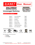
1
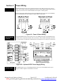
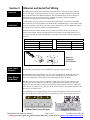
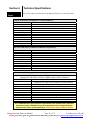
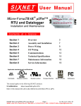
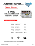
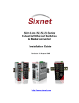
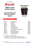
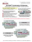
Industrial Ethernet
Managed Switch
Contents at a Glance:
Section 1
General Information
Page 3
Section 2
LED Indicators
Page 4
Section 3
Installation
Page 5
Section 4
Power Wiring
Page 6
Section 5
Ethernet Wiring
Page 9
Section 6
Technical Specifications
Page 11
Section 7
Service Information
Page 13
Applicable standards and certifications:
Total Quality
Hazardous Locations
Standard Locations
European Directives
Marine & Offshore
US Emissions
This manual applies to the following products:
• ET-5MS-#
• ET-9MS-#
• ET-9MG-#
5-port Managed Ethernet switch with 5 10/100 ports
9-port Managed Ethernet switch with 9 10/100 ports
9-port Managed Ethernet switch with 6 10/100 and 3 Gigabit ports
Managed Switch Hardware Manual
Page 1 of 13
Last Revised: 16-Dec-05
SIXNET • 331 Ushers • Box 767 • Clifton Park, NY 12065 USA • +1 (518) 877-5173 • mailto: [email protected]
SIXNET Protected Technology Policy - SIXNET protects your investment in SIXNET systems with longterm planned technology and our unique Protected Technology Policy. We will continue to support the specified
capabilities of standard SIXNET products for at least five years (twenty years for Industrial Managed Switches). We
plan each product improvement and new feature to be upward compatible with existing designs and installations. Our
goals are to make each new software release bring new power to your SIXNET systems and have every existing
feature, applications program and data file continue to work. We protect your investment even further with a liberal
five-year trade-in policy. Exchange standard products for upgraded versions of the same product to take advantage of
new features and performance improvements at any time for five years. A prorated trade-in allowance will be given for
your existing equipment. SIXNET protects your long-term productivity with state-of-the-art planned technology and
continued support.
SIXNET Statement of Limited Warranty - SIXNET, manufacturer of SIXNET products, warrants to Buyer
that products, except software, manufactured by SIXNET will be free from defects in material and workmanship.
SIXNET's obligation under this warranty will be limited to repairing or replacing, at SIXNET's option, the defective
parts within one year of the date of installation, or within 18 months of the date of shipment from the point of
manufacture, whichever is sooner. Products may be returned by Buyer only after permission has been obtained from
SIXNET. Buyer will prepay all freight charges to return any products to the repair facility designated by SIXNET.
This limited warranty does not cover losses or damages which occur in shipment to or from Buyer or due to improper
installation, maintenance, misuse, neglect or any cause other than ordinary commercial or industrial applications. In
particular, SIXNET makes no warranties whatsoever with respect to implied warranties of merchantability or fitness
for any particular purpose. All such warranties are hereby expressly disclaimed. No oral or written information or
advice given by SIXNET or SIXNET’s representative shall create a warranty or in any way increase the scope of this
warranty. This limited warranty is in lieu of all other warranties whether oral or written, expressed or implied.
SIXNET's liability shall not exceed the price of the individual units, which are the basis of the claim. In no event shall
SIXNET be liable for any loss of profits, loss of use of facilities or equipment, or other indirect, incidental or
consequential damages.
INSTALLATION AND HAZARDOUS AREA WARNINGS - These products should not be used to
replace proper safety interlocking. No software-based device (or any other solid-state device) should ever be
designed to be responsible for the maintenance of consequential equipment or personnel safety. In particular,
SIXNET disclaims any responsibility for damages, either direct or consequential, that result from the use of
this equipment in any application. All power, input and output (I/O) wiring must be in accordance with Class I,
Division 2 wiring methods and in accordance with the authority having jurisdiction.
WARNING
(EXPLOSION HAZARD)
SUBSTITUTION OF COMPONENTS MAY IMPAIR SUITABILITY FOR CLASS 1,
DIVISION 2 (ZONE 2).
WARNING
(EXPLOSION HAZARD)
WHEN IN HAZARDOUS LOCATIONS, DISCONNECT POWER BEFORE REPLACING
OR WIRING UNITS.
WARNING
(EXPLOSION HAZARD)
DO NOT DISCONNECT EQUIPMENT UNLESS POWER HAS BEEN SWITCHED OFF
OR THE AREA IS KNOWN TO BE NONHAZARDOUS.
FCC Statement - This equipment has been tested and found to comply with the limits for a Class B digital device, pursuant
to Part 15 of the FCC Rules. These limits are designed to provide reasonable protection against harmful interference in a
residential installation. This equipment generates, uses and can radiate radio frequency energy and, if not installed and used in
accordance with the instructions, may cause harmful interference to radio communications. However, there is no guarantee that
interference will not occur in a particular installation. If this equipment does cause harmful interference to radio or television
reception, which can be determined by turning the equipment off and on, the user is encouraged to try to correct the interference
by one or more of the following measures: Reorient or relocate the receiving antenna; Increase the separation between the
equipment and receiver; Connect the equipment into an outlet on a circuit different from that to which the receiver is connected;
Consult the dealer or an experienced radio/TV technician for help.
Copyright & Trademarks - Copyright ©2005 SIXNET, All Rights Reserved. EtherTRAK is a registered
trademark of SIXNET.
Note: All information in this document is subject to change without notice.
Managed Switch Hardware Manual
Page 2 of 13
Last Revised: 16-Dec-05
SIXNET • 331 Ushers • Box 767 • Clifton Park, NY 12065 USA • +1 (518) 877-5173 • mailto: [email protected]
Section 1
Overview
General Information
This manual will help you install and maintain the Managed Switches. Installation of these
managed switches will enable the user to wire redundant connections between nodes, manage the
network by monitoring/gathering network data, allow for browser or telnet configuration, increase
network performance, and more.
Note: This manual only covers the installation and wiring of these switches. Refer
to the separate Software User Manual for details on configuring and using any of
the management functions such as SNMP, RSTP, IGMP, port mirroring, etc.
Operation
Unlike an Ethernet hub that broadcasts all messages out all ports, the Managed Switches will
intelligently route Ethernet messages only out the appropriate port. Most importantly, unlike a
regular Ethernet switch, very resilient networks can be implemented because the Managed Switch
has the intelligence to detect and allow for ring Ethernet topologies. In other words, implementing
this switch will optimize the network for optimal bandwidth conditions, reduce the number of
collisions, and allow for redundant data path connections to reduce/eliminate downtime.
To further aid in network reliability and performance, SNMP is available to extract and exchange
network statistical information. Through the use of SNMP, various groups of statistical information
can be obtained such as TCP, RMON, IP, and more to aid the user’s job to extrapolate the “health”
of the network.
The Managed Switches can support 10BaseT (10 Mbps), 100BaseT (100 Mbps) and 1000BaseT
(1000Mbps) on their RJ45 ports (depending on the model). Each of these ports will independently
auto-sense the speed, allowing you to interface to regular, fast or gigabit Ethernet devices. Some
models also have one or two 100BaseF (100 Mbps) or 1000BaseF (1000 Mbps) fiber optic ports.
Performance
Specifications
These general specifications apply to the Managed Switches. Refer to Section 7 for complete
technical specifications.
5 or 9 Ethernet ports
Ethernet Switch Type: Managed with SNMP, RSTP, IGMP, VLANs and much more
Ethernet Protocols: All standard IEEE 802.3
RJ45 Ports (shielded): 10/100 or 10/100/1000 (with auto-negotiation, auto-crossover and auto-polarity)
Fiber optic port speed: 100 or 1000 Mbps depending on transceiver installed
Fiber optic wavelength: 850, 1300, 1310 or 1550 nm depending on transceiver installed
Standards
and Safety
The Managed Switches meet the following standards plus others:
Electrical safety - UL 508, CSA C22; EN61010-1 (IEC1010)
EMI emissions - FCC part 15, ICES 003, EN55022; Class B
EMC immunity – IEC61326-1, IEEE C37.90
Hazardous locations – UL 1604, CSA C22.2/213 (Class 1, Div. 2), Groups A, B, C, D; Cenelec
EN50021 (Zone 2)
Install the Managed Switches in accordance with local and national electrical codes.
Lightning Danger: Do not work on equipment during periods of lightning activity.
Do not connect a telephone line into one of the Ethernet RJ45 connectors.
Managed Switch Hardware Manual
Page 3 of 13
Last Revised: 16-Dec-05
SIXNET • 331 Ushers • Box 767 • Clifton Park, NY 12065 USA • +1 (518) 877-5173 • mailto: [email protected]
Section 2
Overview
LED Indicators
The Managed Switches have communication LEDs for each port, an “OK” output LED, a status
LED and power LEDs. Refer to the sample pictures below for the location of these LEDs.
Port
LEDs
Typical LED Location on
the Managed Switches
(varies with model)
Power
and
Status
LEDs
Power LEDs
There are two Power LEDs on the Managed Switch that are above the P1 and P2 terminals. P1 is
used for primary power and P2 is used for secondary power. Both indicate if there is power applied
to the respective terminal.
ACT / LNK /
(10/100) LEDs
The column of LEDs along the left side of the Managed Switch is associated with their
corresponding port numbers printed next to them. These are multifunctional LEDS capable of
indicating link confirmation, activity, and speed.
Off
This would indicate that there is not a proper Ethernet connection (Link)
between the port and another Ethernet device. Make sure the cable has been
plugged securely into the ports at both ends.
This would indicate that there is a proper Ethernet connection (Link)
On Solid
between the port and another Ethernet device, but no communications
(not flashing) activity is detected.
OK LED
Flashing
This would indicate that there is a proper Ethernet connection (Link)
between the port and another Ethernet device, and that there is
communications activity.
Red
Green
Yellow
A 1000 Mbps (1000BaseT) connection is detected.
A 100 Mbps (100BaseT) connection is detected.
A 10 Mbps (10BaseT) connection is detected.
This LED indicates the status of the power inputs. There is an output screw terminal that can be
connected as shown in Figure 4A and 4B. The output voltage from the screw terminal marked ‘OK’
will be the same as the applied switch input voltage. The output will be ON when both the PI and
P2 terminals have power applied to them. It will be OFF if either input does not have power or the
switch software is not running.
Managed Switch Hardware Manual
Page 4 of 13
Last Revised: 16-Dec-05
SIXNET • 331 Ushers • Box 767 • Clifton Park, NY 12065 USA • +1 (518) 877-5173 • mailto: [email protected]
Section 3
Installation
The Managed Switches can be snapped onto a standard DIN rail (EN50022) or screwed directly to a
flat panel. Refer to the mechanical drawing below. Note: Make sure to allow enough room to route
your Ethernet cables.
Overview
Note: The Managed Switches are design to snap tightly to a standard DIN rail. This
is done by hooking the top (connector side) of the switch on the DIN rail first and
then pushing in on the bottom side until you hear a click. However, if the DIN rail is
misshapen or bent you may need to use a screwdriver to slide the integral clip away
from the switch as you install it to the DIN rail. Once the switch is flat to the DIN rail
then you can release the clip for proper attachment.
6.250"
[15.88 cm]
ST fiber
SC fiber
0.275"
[0.70 cm]
0.400"
[1.02 cm]
(max. for
ST fiber)
0, 1 or 2 Fiber
(SC or ST)
DIN EN
50022
(not
included)
3.770"
[9.58 cm]
Front View
3.535"
[8.98 cm]
0.835"
[2.12 cm]
5.975"
[15.18 cm]
1.38" [3.5 cm]
2.30"
[5.84 cm]
Side View
2.187"
[5.55 cm]
1.95"
[4.95 cm]
1.583"
[4.02 cm]
DIN EN50022
(not included with units)
(not shown to scale)
(for reference only)
1.06" [2.7 cm]
0.30"
[0.76 cm]
Figure 3A – Mechanical Dimensions for 9-Port Model
Managed Switch Hardware Manual
Page 5 of 13
Last Revised: 16-Dec-05
SIXNET • 331 Ushers • Box 767 • Clifton Park, NY 12065 USA • +1 (518) 877-5173 • mailto: [email protected]
Note: Some SFP (Mini-Gbic) modules (copper or
fiber) may protrude more than shown in this
drawing. Make sure you allow enough room for
the pluggable module and cable you are using.
Figure 3B – Mechanical Dimensions for Gigabit Model
Managed Switch Hardware Manual
Page 6 of 13
Last Revised: 16-Dec-05
SIXNET • 331 Ushers • Box 767 • Clifton Park, NY 12065 USA • +1 (518) 877-5173 • mailto: [email protected]
ST Fiber
0.40"
[1.02 cm]
(max. for
ST Fiber)
5, 4 or 3
Copper Ports
(RJ45)
SC Fiber
0.275"
[0.70 cm]
0, 1 or 2
Fiber Ports
(SC or ST)
3.17"
[8.05 cm]
2.935"
[7.45 cm]
DIN EN
50022
(not
included)
Front View
0.235"
[0.60 cm]
1.60"
[4.07 cm]
Power & Alarm
ET-5MS
ET-5RS
0.17"
[0.43]
(clear for
#8 screw)
4.475" [11.37 cm]
4.75" [12.07 cm]
0.35" [0.90 cm]
1.38" [3.5 cm]
Side View
All copper & single fiber models:
A = 1.45" [3.68 cm]
A
DIN EN50022
(not included with units;
not shown to scale;
for reference only)
Dual fiber model:
A = 1.95" [4.95 cm]
0.30"
[0.76 cm]
1.06" [2.7 cm]
Figure 3C – Mechanical Dimensions for 5-Port Model
Managed Switch Hardware Manual
Page 7 of 13
Last Revised: 16-Dec-05
SIXNET • 331 Ushers • Box 767 • Clifton Park, NY 12065 USA • +1 (518) 877-5173 • mailto: [email protected]
Section 4
Overview
Power Wiring
The Managed Switches can be powered from the same DC source that is used to power your I/O
devices. 10 to 30 VDC needs to be applied between the P1 terminal and the Minus terminal (shown
in Figure 4A). The first screw terminal should be tied to panel or chassis ground.
To reduce down time resulting from power loss, the Managed Switch can be powered redundantly.
Refer to the Redundant DC Power diagram in Figure 4B for wiring details.
Figure 4A – Power & Alarm Wiring
RM-PS-024-01N
(optional)
The optional RM-PS-024-01 can be used to power your Managed Switches, instrumentation loops,
and other devices. It operates on 85-264 VAC (47-63 Hz) or 120-370 VDC and outputs 24 VDC at
up to 1 Amp. Refer to its data sheet for details. Refer to the figure below for the power connections.
Optional Auxiliary
DC Power Input
GND
DC+
Chassis
DC GND
DC GND
DC+ OUT
DC+ OUT
Opt. Auxiliary
Power Input
DC GND
DC+ IN
Line
Line
Neutral
Neutral
Chassis
DC GND
DC + IN
DC GND
DC GND
DC GND
DC GND
DC GND
DC GND
DC GND
DC GND
DC+ OUT
DC+ OUT
DC+ OUT
DC+ OUT
DC+ OUT
DC+ OUT
DC+ OUT
DC+ OUT
AC
Power
Input
Extra terminals
for 4-20 loops,
fields devices
and more
Line
Line
Neutral
Neutral
Chassis GND
DC
DC +
DC +
Power
DC -Output
DC -Chassis GND
Optional
Auxiliary
DC Input
4-20
Input
Field
Device
Discrete
Output
Discrete
Input
DC Power for controllers,
RTUs, I/O, and user loops
Wiring Base
Figure 4B – Optional AC/DC Power Supply Wiring
Screw Torque
When tightening the screws of the Managed Switch or the screws of the RM-PS-024-01 power
supply, be careful to tighten to a maximum of 3.48 lb-in.
Managed Switch Hardware Manual
Page 8 of 13
Last Revised: 16-Dec-05
SIXNET • 331 Ushers • Box 767 • Clifton Park, NY 12065 USA • +1 (518) 877-5173 • mailto: [email protected]
Section 5
Ethernet and Serial Port Wiring
Overview
The Managed Switches provides connections to Ethernet devices on the factory floor, managed
devices, and agents. Typically the fiber port is used to connect to another Ethernet switch or hub
that is connected to the main Ethernet backbone. The other Ethernet ports are then connected to
Ethernet devices such as PLCs, Ethernet I/O, or industrial computers. Electrical isolation is
provided on the Ethernet ports for increased reliability.
RJ45 Wiring
Guidelines
Use data-quality (not voice-quality) twisted pair cable rated category 5 (or better) with standard
RJ45 connectors. For best performance use shielded cable. Straight through or crossover RJ45 cable
can be used regardless of the device the switch is to be connected to as all these Managed Switches
are capable of auto-crossover of MDI versus MDIX detection.
The RJ45 serial port connector bodies on these products are metallic and are connected to the
Chassis GND terminal. Therefore, shielded cables may be used to provide further protection. To
prevent ground loops, the cable shield should be tied to the metal connector body at one end of the
cable only.
Straight-thru Cable Wiring
Pin 1
Pin 1
Pin 2
Pin 2
Pin 3
Pin 3
Pin 6
Pin 6
Cross-over Cable Wiring
Pin 1
Pin 3
Pin 2
Pin 6
Pin 3
Pin 1
Pin 6
Pin 2
Ethernet
Connector
Pin Positions
RJ45 Cable
Distance
Ethernet
Fiber Wiring
Guidelines
The maximum cable length for 10/100/1000BaseT is typically 100 meters (328 ft.).
The Managed Switches optionally have one or two pair of multimode or singlemode fiber ports.
The maximum segment length is up to 120 km or more depending on the type of fiber optic
transceiver installed in the switch. Refer to the technical specifications for details.
Each fiber optic port on the switch is comprised of a pair of SC, ST or LC style connectors. For
each fiber port there is a transmit (TX) and receive (RX) signal. When making your fiber optic
connections, make sure that the transmit (TX) port of the switch connects to the receive (RX) port
of the other device, and the receive (RX) port of the switch connects to the transmit (TX) port of the
other device. See images below.
Use standard fiber optic wiring techniques (not covered by this manual) to make your connections.
The corresponding ACT/LNK LED will be ON solid when you have made a proper connection.
100BaseT Fiber Ports (SC Style)
Managed Switch Hardware Manual
Page 9 of 13
Last Revised: 16-Dec-05
SIXNET • 331 Ushers • Box 767 • Clifton Park, NY 12065 USA • +1 (518) 877-5173 • mailto: [email protected]
Duplex
Operation
The RJ45 ports will auto-sense for Full or Half duplex operation, while the fiber ports are
configured for full duplex operation. Note: Fiber devices with half duplex settings should still
communicate with the switch. If otherwise then contact your switch vendor.
Network
Device Check
The Managed Switches are capable of supporting 10/100/1000BaseT and 100 or 1000BaseF. Make
sure you connect the appropriate devices to each port.
Verifying
Connectivity
After all Ethernet and/or fiber connections are made, check the LED’s corresponding to the ports
that each of the devices are connected to. Ensure that for each port that is in use, the LED is on or
blinking. If a port LED is off, go back and check for connectivity problems between that port and
the network device connected to that particular port. In addition, the color of the LED should
indicate the speed for which your device is connected at (see prior section on LEDs).
Serial Port
Wiring
An RJ45 female connector for this port is used to configure the networking and management
options for the Managed Switches. Included with the Managed Switches is a pre-wired DB9F to
RJ45F adapter. Use this adapter along with a RJ45 male to RJ45 male straight-thru wired patch
cable (not included) to make a connection between a com port on your PC (DB9 male) and the
RS232 port of the Managed Switch (RJ45 female).
Although the provided DB9F to RJ45F adapter is pre-wired, the user could make one by following
the wiring table below:
Switch
RJ45F Pin #,
Signal Name
1 RI/DSR in
2 DCD in
3 DTR out
4 GND
5 RXD in
6 TXD out
7 CTS in
8 RTS out
RJ45F to DB9F
Adapter
wire color
Blue
Orange
Black
Red
Green
Yellow
Brown
White
DB9 Female Connector
Pin #, Signal Name
4 DTR out
N/C
6 DSR in
5 GND
3 TXD out
2 RXD in
7 RTS out
8 CTS in
DB9F to RJ45F Adapter (supplied)
Managed Switch Hardware Manual
Page 10 of 13
Last Revised: 16-Dec-05
SIXNET • 331 Ushers • Box 767 • Clifton Park, NY 12065 USA • +1 (518) 877-5173 • mailto: [email protected]
Section 6
Technical
Specs
Technical Specifications
Here are the technical specifications for the Managed Switches covered by this manual.
Copper RJ45 Ports: (10/100BaseT or 10/100/1000BaseT)
10/100/1000BaseT ports
Protocols supported
Ethernet compliancy
Auto-crossover
Auto-sensing operation
Auto-negotiating
Auto-polarity
Flow control
Ethernet isolation
Plug and play
Cable requirements
Max. cable distance
Shielded RJ45
All standard IEEE 802.3
IEEE 802.3, 802.3u, 802.3x, 802.3z, 802.1p and more
Yes, allows you to use straight or cross wired cables
Full and half duplex
10BaseT and 100BaseT and 1000BaseT as applicable
Yes, on the TD and RD pair
Automatic
1500 VRMS 1 minute
Yes
Twisted pair (Cat. 5 or better) (shielded recommended)
100 meters
SC or ST Fiber Ports: (100BaseF multimode or singlemode)
100BaseF ports
Fiber port mode
Fiber port connector
Optimal fiber cable
Center wavelength
TX output power
RX input sensitivity
Max. distance (full duplex)
Half and full duplex
Ethernet compliance
Eye safety
Up to 2
Multimode (mm) or Singlemode (sm)
Duplex SC or ST
62.5/125 µm for mm; 9/125 µm for sm
1300 nm
Contact your switch vendor
Contact your switch vendor
2 km with mm; 15 km with sm, 70+ km with long haul sm
Software Configurable
100BaseF
IEC 60825-1, Class 1; FDA 21 CFR 1040.10 and 1040.11
SFP Mini-Gbic SFP (pluggable) Ports: (many types available)
Note: Ports 8 and 9 on the Gigabit models are pluggable and accept many different types of
pluggable SFP (Mini-Gbic) modules for Gigabit copper or fiber connections.
Gigabit ports
Up to 2
Port types
Copper RJ45, fiber multimode, fiber singlemode, fiber long haul
singlemode, fiber single strand, 1000BaseF (SX/LX/LH) modules
Fiber port connector
RJ45 for copper; LC typically for fiber (depends on module)
Optimal fiber cable
62.5/125 µm for multimode (mm); 9/125 µm for singlemode (sm)
Fiber wavelength
850 nm for mm; 1310 nm for sm; 1550 for long haul sm
TX output power
Contact your switch vendor
RX input sensitivity
Contact your switch vendor
Max. distance (full duplex)
Up to 120+ km with long haul singlemode modules
Half and full duplex
Software Configurable
Ethernet compliance
1000BaseT and 1000BaseF (SX/LX/LH)
Eye safety
IEC 60825-1, Class 1; FDA 21 CFR 1040.10 and 1040.11
Note: Additional fiber optic transceiver specifications are available. Also, other fiber
transceivers may be available for special requirements such as longer distances,
single strand or other special applications. Contact your switch vendor for details.
Managed Switch Hardware Manual
Page 11 of 13
Last Revised: 16-Dec-05
SIXNET • 331 Ushers • Box 767 • Clifton Park, NY 12065 USA • +1 (518) 877-5173 • mailto: [email protected]
General Specifications:
Ethernet switch type
Latency for 10 Mbps ports
Latency for 100 or 1000 ports
Full or half duplex operation
Managed with 5 or 9 Ethernet ports
16 us + frame time (typical)
Varies on load and settings
5 us + frame time (typical)
Configurable
“OK” Output
Voltage
Maximum current output
ON if P1 and P2 have power and switch software is running
Same as switch input voltage
0.5 Amp
Environmental
Power input
Input power (typical - all
ports active at 100 Mbps)
(10 W maximum)
DIN rail or direct panel mounting
Redundant Input Terminals
5.0 W (5-port model)
7.0 W (9-port without fiber ports)
8.0 W (9-port 1 fiber)
9.0 W (9-port with 2 fiber)
10-30 VDC (continuous)
15,000 watts peak
5,000 watts (10x for 10 uS)
Models -4 & -5 only
Exceeds MIL-STD-1275
100V for 1 second
5,000 watts (10x for 10 uS) or
250 volts (50x for 100 uS)
1500 VRMS 1 minute
-40 to +74 °C
-40 to +85 °C
5 to 95% RH
IEC68-2-6
UL508/CSA C22, EN61010-1
FCC part 15, ICES-003, EN55022
IEC61326-1, IEEE C37.90
UL1604, CSA C22.2/213 (Class 1,
Div. 2), Cenelec EN50021 (Zone 2)
DNV (Det Norske Veritas)
IEC60825-1, Class 1; FDA 21 CFR
1040.10 and 1040.11
IP20 or IP30 protection (Lexan & alum. case)
See mechanical diagrams for details
Input voltage (all models)
Transient protection
Spike protection
Extended protection
Military surge protection
Maximum voltage surge
Maximum voltage spike
Ethernet isolation
Operating temperature range
Storage temperature range
Humidity (non-condensing)
Vibration
Electrical safety
EMI emissions
EMC immunity
Hazardous locations
Marine and off-shore tested
Eye safety (fiber models)
Packaging
Dimensions (L x W x H)
Managed Switch Hardware Manual
Page 12 of 13
Last Revised: 16-Dec-05
SIXNET • 331 Ushers • Box 767 • Clifton Park, NY 12065 USA • +1 (518) 877-5173 • mailto: [email protected]
Section 8
Service
Information
Service Information
We sincerely hope that you never experience a problem with any SIXNET product. If you do need
service, call SIXNET at (518) 877-5173 and ask for Applications Engineering. A trained specialist
will help you to quickly determine the source of the problem. Many problems are easily resolved
with a single phone call. If it is necessary to return a unit to us, an RMA (Return Material
Authorization) number will be given to you.
SIXNET tracks the flow of returned material with our RMA system to ensure speedy service. You
must include this RMA number on the outside of the box so that your return can be processed
immediately.
The applications engineer you are speaking with will fill out an RMA request for you. If the unit
has a serial number, we will not need detailed financial information. Otherwise, be sure to have
your original purchase order number and date purchased available.
We suggest that you give us a repair purchase order number in case the repair is not covered under
our warranty. You will not be billed if the repair is covered under warranty.
Please supply us with as many details about the problem as you can. The information you supply
will be written on the RMA form and supplied to the repair department before your unit arrives.
This helps us to provide you with the best service, in the fastest manner. Normally, repairs are
completed in two days. Sometimes difficult problems take a little longer to solve.
If you need a quicker turnaround, ship the unit to us by air freight. We give priority service to
equipment that arrives by overnight delivery. Many repairs received by mid-morning (typical
overnight delivery) can be finished the same day and returned immediately.
We apologize for any inconvenience that the need for repair may cause you. We hope that our rapid
service meets your needs. If you have any suggestions to help us improve our service, please give
us a call. We appreciate your ideas and will respond to them.
For Your Convenience:
Please fill in the following and keep this manual with your SIXNET system for future reference:
P.O. #:__________________ Date Purchased: ___________________
Purchased From:______________________________________________
Product
Support
To obtain support for SIXNET products:
On-line support: http://www.get2support.com
Order on-line: http://www.sixnetstore.com
Latest product info: http://www.sixnetswitch.com
Phone: +1 (518) 877-5173
Fax: +1 (518) 877-8346
E-mail: mailto: [email protected]
Mailing address: SIXNET, 331 Ushers Road, P.O. Box 767, Clifton Park, NY 12065
Managed Switch Hardware Manual
Page 13 of 13
Last Revised: 16-Dec-05
SIXNET • 331 Ushers • Box 767 • Clifton Park, NY 12065 USA • +1 (518) 877-5173 • mailto: [email protected]