1
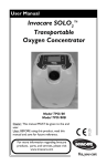
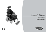
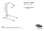
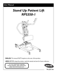
Invacare® REM 550
Supplement to power wheelchair user manual
en
This manual MUST be given to the user of the product.
BEFORE using this product, read this manual and save for future reference.
Remote
User Manual
©2015 Invacare® Corporation
All rights reserved. Republication, duplication or modification in whole or in part is prohibited without
prior written permission from Invacare. Trademarks are identified by ™and ®. All trademarks are
owned by or licensed to Invacare Corporation or its subsidiaries unless otherwise noted.
Contents
1 General . . . . . . . . . . . . . . . . . . . . . . . . . . . . . . . . . . . . . . . . 4
1.1 About this manual . . . . . . . . . . . . . . . . . . . . . . . . . . . . . . 4
2 Components . . . . . . . . . . . . . . . . . . . . . . . . . . . . . . . . . . . . 5
2.1 Remote construction . . . . . . . . . . . . . . . . . . . . . . . . . . . . 5
2.1.1 General view . . . . . . . . . . . . . . . . . . . . . . . . . . . . . . . 5
2.1.2 Top side. . . . . . . . . . . . . . . . . . . . . . . . . . . . . . . . . . . 5
2.1.3 Bottom . . . . . . . . . . . . . . . . . . . . . . . . . . . . . . . . . . . 6
2.2 Status display . . . . . . . . . . . . . . . . . . . . . . . . . . . . . . . . . . 7
2.2.1 Battery charge display . . . . . . . . . . . . . . . . . . . . . . . . . 7
2.2.2 Battery alarms . . . . . . . . . . . . . . . . . . . . . . . . . . . . . . 7
2.2.3 System status . . . . . . . . . . . . . . . . . . . . . . . . . . . . . . . 8
3 Usage . . . . . . . . . . . . . . . . . . . . . . . . . . . . . . . . . . . . . . . . . .
3.1 Using Buddy Buttons with the remote . . . . . . . . . . . . . . . .
3.2 Steering the wheelchair with the remote . . . . . . . . . . . . . .
3.2.1 How to find out which steering gear your wheelchair
has. . . . . . . . . . . . . . . . . . . . . . . . . . . . . . . . . . . . . .
3.2.2 How a wheelchair with "Indirect Steering" reacts to
joystick movements. . . . . . . . . . . . . . . . . . . . . . . . . .
3.2.3 How a wheelchair with "Direct Steering" reacts to
joystick movements. . . . . . . . . . . . . . . . . . . . . . . . . .
3.3 Switching the wheelchair off . . . . . . . . . . . . . . . . . . . . . . .
3.4 Locking/unlocking the wheelchair . . . . . . . . . . . . . . . . . . .
3.4.1 Locking the wheelchair . . . . . . . . . . . . . . . . . . . . . . . .
3.4.2 Unlocking the wheelchair . . . . . . . . . . . . . . . . . . . . . .
3.5 Switching the lights on and off. . . . . . . . . . . . . . . . . . . . . .
3.6 Switching the warning lights on and off . . . . . . . . . . . . . . .
3.7 Operating the electrical adjustment options. . . . . . . . . . . .
3.7.1 Which symbols are displayed and what they mean . . . .
3.7.2 Activate setting mode . . . . . . . . . . . . . . . . . . . . . . . . .
9
9
9
11
11
11
12
12
12
13
13
13
14
14
14
3.7.3 Selecting and actuating adjustment options . . . . . . . .
3.7.4 Changing from setting mode to drive mode . . . . . . .
3.8 Further adjustment options for remotes up to July
2014. . . . . . . . . . . . . . . . . . . . . . . . . . . . . . . . . . . . .
3.8.1 Deactivating programming mode (remotes up to July
2014) . . . . . . . . . . . . . . . . . . . . . . . . . . . . . . . . . .
3.8.2 Changing the screen brightness (remotes up to July
2014) . . . . . . . . . . . . . . . . . . . . . . . . . . . . . . . . . .
3.8.3 Setting the time (remotes up to July 2014) . . . . . . . .
3.8.4 Display/hide time display (remotes up to July 2014) . .
3.8.5 Changing the screen background (remotes up to July
2014) . . . . . . . . . . . . . . . . . . . . . . . . . . . . . . . . . .
3.9 Further adjustment options for remotes since July
2014. . . . . . . . . . . . . . . . . . . . . . . . . . . . . . . . . . . . .
3.9.1 Deactivating programming mode (remotes since July
2014) . . . . . . . . . . . . . . . . . . . . . . . . . . . . . . . . . .
3.9.2 Changing the screen brightness (remotes since July
2014) . . . . . . . . . . . . . . . . . . . . . . . . . . . . . . . . . .
3.9.3 Setting the time (remotes since July 2014) . . . . . . . .
3.9.4 Display/hide time display (remotes since July 2014) . .
3.9.5 Changing the screen background (remotes since July
2014) . . . . . . . . . . . . . . . . . . . . . . . . . . . . . . . . . .
. . 15
. . 15
. . 16
. . 16
. . 16
. . 17
. . 17
. . 18
. . 18
. . 18
. . 19
. . 19
. . 20
. . 20
4 Troubleshooting . . . . . . . . . . . . . . . . . . . . . . . . . . . . . . . . . 21
4.1 Error diagnosis . . . . . . . . . . . . . . . . . . . . . . . . . . . . . . . . 21
4.1.1 Error codes and diagnosis codes . . . . . . . . . . . . . . . . . 21
Invacare® REM 550
1 General
1.1 About this manual
This document is a supplement to the power wheelchair’s
documentation.
The product itself does not bear a CE mark but is part of a product
that complies with Directive 93/42/EEC concerning medical devices.
It is therefore covered by the power wheelchair’s CE marking. See
the power wheelchair’s documentation for more information.
4
1528090-F
Components
2 Components
2.1.2 Top side
Displays and controls
2.1 Remote construction
2.1.1 General view
Displays and controls
A ON/OFF key
B Direction indicators right and warning blinker
C Activate setting mode/switch-through
D Horn
E Activate drive mode/switch-through
A
Joystick
B
Display
Drive mode is shown through numbers 1 to 5 in the display.
F Function key
G Direction indicators left and light
1528090-F
5
Invacare® REM 550
Display (remotes up to July 2014)
Assignment of display fields in display to keys
2.1.3 Bottom
1)
Socket for charging cable and for programming the remote
2)
Socket for bus cable
3)
Socket I for Buddy Button (corresponds to "Activate drive
mode/switch-through" key). This key is deactivated as
standard.
4)
ON/OFF socket for Buddy Button (corresponds to
"ON/OFF" key)
5)
Socket II for Buddy Button (corresponds to "Activate setting
mode" key).
A Status bar indicator
B Drive mode or setting mode display
Display (remotes since July 2014)
This key is deactivated as standard.
The cover cap must be removed if sockets 2 to 5 are to be
used. To do this, remove the Phillips screw.
Assignment of display fields in display to keys
A Drive mode screen
B Acessory mode screen
6
1528090-F
Components
2.2 Status display
The battery symbol illuminates green (5 bars):
Maximum driving range!
The battery symbol illuminates yellow (4 bars):
Decreased driving range!
Remotes up to July 2014
Remotes since July 2014
The status display is located at the top edge of the screen. It contains
the following information:
•
•
A
Battery (for remotes up to July 2014)
4Q Mode option (for remotes since July 2014)
The battery symbol illuminates yellow (3 bars):
Decreased driving range! Charge the batteries.
The battery symbol illuminates red (2 bars):
Low driving range! Charge the batteries as
soon as possible.
B
Direction indicators left, warning blinker
The battery symbol illuminates red (1 bar):
C
Light
Very low driving range! Charge the batteries
immediately.
D
System status
If the system is working without faults, no symbol is
displayed.
If a fault occurs, the "spanner" symbol is displayed with an
error code.
E
Direction indicators right , warning blinker
F
Time
The battery symbol illuminates red (no bars):
Driving range exhausted! Charge the batteries
immediately.
To protect against total battery discharge, the electronics
system automatically switches the drive to battery reserve
after a specified driving time, and the wheelchair will come
to a standstill.
2.2.1 Battery charge display
2.2.2 Battery alarms
The battery charging status is shown in the screen status display.
Alarms concerning the battery charging status are displayed in the
centre of the screen.
1528090-F
7
Invacare® REM 550
•
The battery symbol illuminates red (completely full):
The batteries are overcharged!
1.
2.
Disconnect the battery charger.
Switch the lights on.
•
The battery symbol illuminates red and is crossed out:
The batteries are empty!
1.
2.
Switch the wheelchair off.
Charge the batteries immediately.
2.2.3 System status
The system status is shown in the middle of the status display if
a fault occurs.
An error code is displayed to the right of the "spanner" symbol. You
can use this error code to help find the cause of the fault as described
in Chapter 4.1 Error diagnosis, page 21.
8
1528090-F
Usage
3 Usage
The cover cap must be removed if sockets 1 to 3 are to be
used. To do this, remove the Phillips screw.
3.1 Using Buddy Buttons with the remote
3.2 Steering the wheelchair with the remote
What is a Buddy Button?
– A Buddy Button (4) is an additional button which can
be used to activate remote functions. The sockets for
Buddy Buttons are located underneath the remote.
1)
Socket I
(corresponds to "Activate drive mode/switch-through" key)
The button is deactivated as standard.
2)
Remotes up to July 2014
1.
2.
3.
4.
ON/OFF socket
(corresponds to "ON/OFF" key)
3)
The necessary force to operate the joystick and input
buttons is less than 13.5 N. This complies with the
requirements of ISO 7176-14.
Socket II
(corresponds to "Activate setting mode" key)
5.
Press the "ON/OFF" key.
The display illuminates.
The mode display A shows the drive level.
The wheelchair is ready to drive.
You can set the drive levels using the drive mode key C. In this
case, drive level 1 is the slowest and drive level 5 the fastest
setting.
Within each drive level you can carry out fine settings for the
speed using the function key B. The fine settings are displayed
in the ring D. This enables, for example, adapting the speed to
that of an attendant.
The button is deactivated as standard.
4)
Buddy Button
1528090-F
9
Invacare® REM 550
Remotes since July 2014
green
Normal drive operation.
orange
Wheelchair can drive or is driving in a
restricted capacity (that is, reduced speed).
red
Inhibited state (flashing) – the chair cannot be
driven in this state.
The G-Trac™ option
1.
2.
3.
4.
5.
Press the "ON/OFF" key.
The display illuminates.
The mode display A shows the drive level (see drive limit status
below).
The wheelchair is ready to drive.
You can set the drive levels using the drive mode key D. In this
case, drive level 1 is the slowest and drive level 5 the fastest
setting. In the example above, drive level 4 is for a medium-fast
setting. The orange marker B indicates the maximum speed
for each drive level.
Within each drive level you can carry out fine settings for the
speed using the function key C. The fine settings are displayed
in the ring E. This enables, for example, adapting the speed to
that of an attendant.
If your mobility device has been fitted with the G-Trac
option you will NOT be able to change driving profiles while
travelling.
If your mobility device has been fitted with the G-Trac option, it will
enable you to enjoy fatigue-free and safer driving.
•
•
•
G-Trac supports you in staying at the same driving speed and
travel direction, and therefore reduces fatigue.
It improves the tracking and therefore increases the user's
driving comfort.
G-Trac stabilizes the mobility device tracking in the case of
front-wheel-drive devices and finds the optimum driving speed
for travelling round bends. This prevents skidding, slipping or
tipping of the mobility device and therefore increases safety.
The drive limit status (remotes since July 2014)
The color of the current drive profile, shown in the middle of the
screen, is dependent on the wheelchair’s status.
10
1528090-F
Usage
Can the electronic system programming be adapted?
CAUTION!
Any alteration to the drive programme can
influence vehicle handling and the tipping stability
of the mobility device
– Alterations to the drive programme may only be
carried out by trained Invacare dealers.
– Invacare supplies all electric vehicles from the factory
with a standard drive programme. Invacare can only
assume a warranty for the safe vehicle handling of the
mobility device – in particular tipping stability - for this
standard drive programme.
3.2.2 How a wheelchair with "Indirect Steering"
reacts to joystick movements
"Indirect Steering" occurs by individually applying power to the drive
wheels, and is found on wheelchairs with front, rear and middle
wheel drive.
The electronic controller is programmed with standard values during
manufacture. Your Invacare dealer can carry out programming
tailored to fit your requirements.
Is the wheelchair not ready to go after switching on?
1.
2.
Check the status display (refer to2.2.3 System status, page 8 ).
If an error code is shown on the status display, you can recognize
and rectify the fault with the help of chapter 4.1 Error diagnosis,
page 21.
3.2.1 How to find out which steering gear your
wheelchair has
In the case of a wheelchair with indirect steering, control takes place
via the separate drive wheel controller. Indirect steering is used for
wheelchairs with front wheel, rear wheel and central drive.
In the case of a wheelchair with direct steering, control takes place
via a servo motor.
Travel direction
The further the joystick
is moved in a particular
direction, the more
dynamically the wheelchair
reacts.
To brake quickly, simply let go of the joystick. It then
automatically returns to the middle position. The wheelchair
brakes.
3.2.3 How a wheelchair with "Direct Steering" reacts
to joystick movements
Steering is operated by means of a servo motor.
The controller for a wheelchair with indirect and direct steering is
described below.
1528090-F
11
Invacare® REM 550
Travel direction
The further the joystick
is moved in a particular
direction, the more
dynamically the wheelchair
reacts.
To brake quickly, simply let go of the joystick. It then
automatically returns to the middle position. The wheelchair
brakes.
1.
Press the "ON/OFF" key (1).
The remote switches off.
3.4 Locking/unlocking the wheelchair
3.4.1 Locking the wheelchair
3.3 Switching the wheelchair off
If you press the "ON/OFF" key while driving, an emergency
stop is carried out. The remote only switches off after this.
1.
12
Press the "ON/OFF" key (1) for more than 4 seconds.
1528090-F
Usage
A lock is shown in the display and the remote switches itself off.
3.5 Switching the lights on and off
3.4.2 Unlocking the wheelchair
1.
Press the direction indicator left key (1) for more than 3 seconds.
The light is switched on or off.
1.
2.
Press the "ON/OFF" key (1).
Press the horn (2) twice within 10 seconds.
Remotes up to July 2014
•
•
•
Remotes since July 2014
The display illuminates.
The mode display A shows the drive level.
The wheelchair is ready to drive.
1528090-F
3.6 Switching the warning lights on and off
1.
Press the direction indicator right key (1) for more than 3
seconds.
The warning lights are switched on or off.
13
Invacare® REM 550
3.7 Operating the electrical adjustment options
Verticalizer
Electrical adjustment options, such as electrical legrests or an
electrical backrest, are carried out as described below.
3.7.1 Which symbols are displayed and what they
mean
Not every wheelchair has all the options. Only the symbols for
functions which the wheelchair actually has available are displayed.
Seat tilting with center of gravity displacement
3.7.2 Activate setting mode
Seat tilt
Backrest angle
Left-hand legrest
Remotes since July 2014
Right-hand legrest
Remotes up to July 2014
Seat lifter
Both leg supports
14
1.
•
Press the "Activate setting mode" key A next to the wheelchair
symbol.
The wheelchair changes to setting mode.
1528090-F
Usage
•
The distance you press the joystick determines the dynamics
of the movement.
If you only press the joystick a little, the actuator will only
move slowly.
If you press the joystick as far as you can, the actuator will
move faster.
3.7.4 Changing from setting mode to drive mode
Remotes since July 2014
Remotes up to July 2014
The mode display B changes to a wheelchair symbol.
3.7.3 Selecting and actuating adjustment options
Remotes since July 2014
Remotes up to July 2014
1.
Remotes up to July 2014
1.
2.
Remotes since July 2014
Press the function key A under the wheelchair symbol or
move the joystick left or right several times until the required
adjustment option is shown in the display.
The corresponding adjustment option (e.g. seat tilting) is shown
on the display.
Press the joystick to the front or rear to activate the actuator.
1528090-F
Press the "Activate drive mode/switch-through" key A.
The remote switches back to drive mode.
Remotes up to July 2014
Remotes since July 2014
The mode display B shows the drive level.
15
Invacare® REM 550
3.8 Further adjustment options for remotes up
to July 2014
Clock display
3.8.1 Deactivating programming mode (remotes up
to July 2014)
The setting options described here are standard settings. The
functions of the buttons can be allocated differently, specific to the
customer, or can be deactivated.
1.
2.
3.
Press the "Activate setting mode" key A next to the P symbol.
Press the function key B or move the joystick right or left until
the required adjustment option is shown in the display.
Press the joystick forward to confirm the required adjustment
option.
You can change the following settings:
Screen brightness
Time
Screen background
3.8.2 Changing the screen brightness (remotes up
to July 2014)
The symbol for screen brightness (see chapter 3.9.1 Deactivating
programming mode (remotes since July 2014), page 18) is shown
in the display.
1.
2.
3.
4.
16
Press the function key B or move the joystick right or left to
change the screen brightness.
The bar underneath the sun symbol shows the adjusted value.
Press the "Activate setting mode" key A or move the joystick
right or left to confirm the required setting options.
To carry out further settings, press the "Activate setting mode"
key A or move the joystick right or left again.
To return to drive mode, press the "Activate drive
mode/switch-through" key C.
1528090-F
Usage
3.8.3 Setting the time (remotes up to July 2014)
The symbol for time (see chapter 3.9.1 Deactivating programming
mode (remotes since July 2014), page 18) is shown in the display.
1.
2.
3.
4.
5.
Press the function key B or move the joystick right or left to
select the individual digits in the time display.
The digit to be changed is shown blinking.
Move the joystick forwards to change the individual digits in the
time display.
Move the joystick to the rear to save the changed time.
To carry out further settings, press the "Activate setting mode"
key A or move the joystick right or left again.
To return to drive mode, press the "Activate drive
mode/switch-through" key C.
3.8.4 Display/hide time display (remotes up to July
2014)
The symbol for time display (see chapter 3.9.1 Deactivating
programming mode (remotes since July 2014), page 18) is shown
in the display.
1.
2.
3.
4.
5.
6.
7.
1528090-F
If the green symbol is shown in the display, the time display is
available.
If the red symbol is shown in the display, the time display is
hidden.
Press the joystick to the right or left to display or hide the time
display.
If you press the joystick forwards when two ticks are displayed
above the function key B, the changes you have made to the
time display will be saved.
If you press the joystick forwards when two crosses are displayed
above the function key B, the changes you have made to the
time display will not be saved.
To carry out further settings, press the "Activate setting mode"
key A or move the joystick right or left again.
To return to drive mode, press the "Activate drive
mode/switch-through" key C.
17
Invacare® REM 550
3.8.5 Changing the screen background (remotes up
to July 2014)
3.9 Further adjustment options for remotes
since July 2014
The automatic screen background setting is standard on
delivery. When the lighting is switched on, the background
will change from white to black.
3.9.1 Deactivating programming mode (remotes
since July 2014)
The setting options described here are standard settings. The
functions of the buttons can be allocated differently, specific to the
customer, or can be deactivated.
The symbol for screen background (see chapter 3.9.1 Deactivating
programming mode (remotes since July 2014), page 18) is shown
in the display.
1.
2.
3.
4.
5.
18
Press the function key B or move the joystick right or left to
select one of the three modes.
Select the screen background by selecting one of the following:
• Select (1) if you want to have a black screen background.
• Select (2) if you want to have a white screen background.
• Select (3) if you want the screen background to be set to
standard.
Press the "Activate setting mode" key A or move the joystick
forwards to save the change.
To carry out further settings, press the "Activate setting mode"
key A or move the joystick right or left again.
To return to drive mode, press the "Activate drive
mode/switch-through" key C.
1.
2.
3.
Press the "Activate setting mode" key A until the cog C is
displayed, and then move the joystick forward, momentarily, to
enter the settings menu.
Press the function key B or move the joystick right or left until
the required adjustment option is shown in the display.
Press the joystick forward to confirm the required adjustment
option.
You can change the following settings:
1528090-F
Usage
Screen brightness
3.9.3 Setting the time (remotes since July 2014)
Time
Clock display
Screen background
3.9.2 Changing the screen brightness (remotes since
July 2014)
The symbol for time (see chapter 3.9.1 Deactivating programming
mode (remotes since July 2014), page 18) is shown in the display.
1.
2.
3.
4.
5.
Press the function key B or move the joystick right or left to
select the individual digits in the time display.
The digit to be changed is shown blinking.
Move the joystick forwards to change the individual digits in the
time display.
Move the joystick to the rear to save the changed time.
To carry out further settings, press the "Activate setting mode"
key A or move the joystick reverse again.
To return to drive mode, press the "Activate drive
mode/switch-through" key C.
The symbol for screen brightness (see chapter 3.9.1 Deactivating
programming mode (remotes since July 2014), page 18) is shown
in the display.
1.
2.
3.
Press the function key B or move the joystick right or left to
change the screen brightness.
To carry out further settings, press the "Activate setting mode"
key A or move the joystick forward or reverse.
To return to drive mode, press the "Activate drive
mode/switch-through" key C.
1528090-F
19
Invacare® REM 550
3.9.4 Display/hide time display (remotes since July
2014)
3.9.5 Changing the screen background (remotes
since July 2014)
The automatic screen background setting is standard on
delivery. When the lighting is switched on, the background
will change from white to black.
The symbol for time display (see chapter 3.9.1 Deactivating
programming mode (remotes since July 2014), page 18) is shown
in the display.
1.
2.
3.
4.
5.
20
If the green symbol D is shown in the display, the time display
is available.
If the red symbol E is shown in the display, the time display
is hidden.
Press the joystick to the right or left to display or hide the time
display.
To carry out further settings, press the "Activate setting mode"
key A or move the joystick reverse.
To return to drive mode, press the "Activate drive
mode/switch-through" key C.
The symbol for screen background (see chapter 3.9.1 Deactivating
programming mode (remotes since July 2014), page 18) is shown
in the display.
1.
2.
3.
4.
Press the function key B or move the joystick right or left to
select one of the three modes.
Select the screen background by selecting one of the following:
• Select (1) if you want to have a black screen background.
• Select (2) if you want to have a white screen background.
• Select (3) if you want the screen background to be set to
automatic.
To carry out further settings, press the "Activate setting mode"
key A or move the joystick reverse.
To return to drive mode, press the "Activate drive
mode/switch-through" key C.
1528090-F
Troubleshooting
If the status display is OFF:
4 Troubleshooting
4.1 Error diagnosis
If the electronic system shows a fault, please use the following
fault-finding guide to locate the fault.
Ensure that the drive electronics system is switched on
before starting any diagnosis.
•
•
•
Check whether the drive electronics system is SWITCHED ON.
Check whether all cables are correctly connected.
Ensure that the batteries are not discharged.
If a fault number is displayed in the status display:
•
Please proceed to the next section.
4.1.1 Error codes and diagnosis codes
The drive electronics system is able to correct some errors automatically. In this case, the code number in the status display will disappear. To do
this switch the remote on and off several times. Wait approx. 5 seconds each time before switching the remote on again. If the error is not
corrected by this process, localise the error using the code numbers listed below.
CODE
NUMBER
FAULT
IMMEDIATE MEASURE
1
Module defective.
-
2
Seat not at driving height
If the lifter is raised, lower it in stages until the
status display goes out. If the lifter is lowered
too far, raise the lifter in stages until the status
display goes out. Only drive when the seat is
at driving height!
Accessory error
Fault in left-hand motor.
Connection loose/defective
or motor defective.
3
1528090-F
FURTHER HELP
•
•
Disconnect batteries.1
Contact your dealer.
-
•
•
Disconnect batteries.1
Contact your dealer.
Check connecting plugs.
•
•
Disconnect batteries.1
Contact your dealer.
-
21
Invacare® REM 550
CODE
NUMBER
FAULT
IMMEDIATE MEASURE
4
Fault in right-hand motor.
Connection loose/defective or
motor defective.
Check connecting plugs.
•
•
Disconnect batteries.1
Contact your dealer.
5
Fault/brake fault on left-hand
motor. Connection
loose/defective or motor
defective.
Check connecting plugs.
•
•
Disconnect batteries.1
Contact your dealer.
Left-hand motor disengaged (in
the case of GB motors)
Engage motor turn the remote on and off.
-
Both motors disengaged (in the
case of standard motors)
Engage motors turn the remote on and off.
-
Fault/brake fault on right-hand
motor. Connection
loose/defective or motor
defective.
Check connecting plugs.
•
•
Disconnect batteries.1
Contact your dealer.
Right-hand motor disengaged (in
the case of GB motors)
Engage motor turn the remote on and off
7
Discharged battery
Charge battery
•
•
Disconnect batteries.1
Contact your dealer.
8
Battery voltage too high.
-
•
•
Drive slowly and try to use more
power by, for example, switching
on the lights.
Contact your dealer.
•
•
Disconnect batteries.1
Contact your dealer.
6
9 or 10
22
Incorrect data transmission
between modules.
-
FURTHER HELP
-
1528090-F
Troubleshooting
CODE
NUMBER
FAULT
11
Motors overloaded.
IMMEDIATE MEASURE
•
•
•
12
1
Compatibility problems between
modules.
-
Switch off the remote, wait a few minutes
and then switch it on again.
Check wheels. These should not be
obstructed.
Select a driving route with less gradients.
FURTHER HELP
•
•
Disconnect batteries.1
Contact your dealer.
•
•
Disconnect batteries.1
Contact your dealer.
Refer to the corresponding chapters about disconnecting and/or removing the batteries in the user manual of your mobility device.
1528090-F
23
Invacare Sales Companies
Australia:
Invacare Australia PTY. Ltd.
1 Lenton Place, North Rocks NSW
2151
Australia
Phone: 1800 460 460
Fax: 1800 814 367
[email protected]
www.invacare.com.au
Canada:
Invacare Canada LP
570 Matheson Blvd E. Unit 8
Mississauga Ontario
L4Z 4G4, Canada
Phone: (905) 890 8300
Fax: (905) 501 4336
United Kingdom:
Invacare Limited
Pencoed Technology Park, Pencoed
Bridgend CF35 5AQ
Tel: (44) (0) 1656 776 222
Fax: (44) (0) 1656 776 220
[email protected]
www.invacare.co.uk
Eastern Europe & Middle East:
Invacare GmbH, EDO
Kleiststraße 49
D-32457 Porta Westfalica
Tel: (49) (0)57 31 754 540
Fax: (49) (0)57 31 754 541
[email protected]
www.invacare.eu.com
1528090-F
Ireland:
Invacare Ireland Ltd,
Unit 5 Seatown Business Campus
Seatown Road, Swords, County Dublin
Tel : (353) 1 810 7084
Fax: (353) 1 810 7085
[email protected]
www.invacare.ie
2015-06-10
*1528090F*
Making Life’s Experiences Possible™
New Zealand:
Invacare New Zealand Ltd
4 Westfield Place, Mt Wellington 1060
New Zealand
Phone: 0800 468 222
Fax: 0800 807 788
[email protected]
www.invacare.co.nz