1
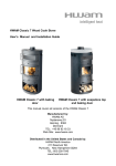
HWAM Monet and HWAM Monet H Wood Stove User’s Manual and Installation Guide HWAM Monet with soapstone and wood compartment HWAM Monet H with soapstone, drawer, and baking door This manual covers all versions of the HWAM Monet and the HWAM Monet H Manufactured by: HWAM AS Nydamsvej 53 Hørning, 8362 Denmark TEL: +45 86 92 18 33 Web Site: www.hwam.com Distributed in the United States and Canada by: HWAM North America 211 Reservoir Rd. Plymouth, New Hampshire 03264 TEL: 603-236-7045 www.hwamna.com Table of Contents 1. Introduction ...........................................................................3 Warnings ............................................................................3 2. Installation ...........................................................................4 Pre Installation Check List ....................................................5 Clearance to combustibles ...................................................6 Floor protection ....................................................................6 Ceiling Height ......................................................................6 Combustible Wall Clearance for top vent installation .........6 Combustible Wall Clearance for rear vent installation .......7 Draft Requirements ..............................................................7 Chimney Installation .............................................................8 Top vent installation ..............................................................9 Chimney connection .............................................................9 Rear vent installation ..........................................................10 Mounting the connector pipe .............................................11 Combustible wall pass throughs ........................................11 Chimney height requirements ............................................14 3. Check the loose parts .........................................................16 4. Instructions for use .............................................................19 Ash Drawer & Ash Grate ..........................................................19 Baffle Plates & Skamol refractory .......................................20 Glass ........................................................................20 Smoke Detectors .......................................................20 Room Ventilation & Draft requirements ..................................21 5. Operation ..............................................................................22 Starting the stove ................................................................23 Refueling the stove ............................................................23 6. Maintenance ....................................................................... 24 Removing Skamol smoke plate for cleaning ......................25 Replacing broken Door Glass .............................................26 7. Troubleshooting ....................................................................27 Automatic Air Control System diagram ...................................28 Spare part list ..............................................................................29 Page 2 1. Introduction We welcome you as a new owner of a HWAM wood-burning stove. The HWAM woodburning stove is one of the finest in the world. This manual will explain the installation, operation and maintenance of the HWAM wood-burning stove. Please familiarize yourself with the owner’s manual before operating your stove and save the manual for future reference. Included are helpful hints and suggestions that will make the operation and maintenance of your new stove an easier and more enjoyable experience. We offer our continued support and guidance. To help you achieve the maximum benefit and enjoyment from your HWAM wood-burning stove. Please read the entire manual carefully before you install and use your new HWAM wood-burning stove. Failure to follow instructions may result in property damage, bodily injury or loss of life. This manual contains important user information. Keep this manual with the stove after installation is complete. Safety and environmental testing HWAM Monet have been tested by OMNI-Test Laboratories, Inc. of Beaverton, Oregon, and are safety listed by OMNI to UL 1482, ULC-S627 and EPA certified. The serial number is fixed to the stove and to the guarantee card. If you need to contact the factory please refer to this serial number. Items included With your HWAM wood-burning stove you will find the following items: 1 instruction and maintenance manual 1 guarantee card 1 oven mitten 1 set of screws for the flue collar Warnings! 1. Keep ash drawer closed during firing in this stove. Use a metal container with a tight fitting lid to dispose of ashes. 2. Never use gasoline, gasoline-type lantern fuel, kerosene, charcoal lighter fluid, or similar liquids to start or ‘freshen up’ a fire in this stove. .Keep all such liquids well away from the stove while it is in use. 3. Do not burn garbage or flammable fluids such as gasoline, naphtha or engine oil. 4. The stove is hot while in operation. Do not touch and keep children, clothing and furniture away. Contact may cause skin burns. .Use gloves when stoking the fire. Page 3 Warnings! 5. Do not connect this stove to a chimney flue connected to another stove or appliance. 6. Do not connect to any air distribution duct or system. 7. Do not install in a mobile home. 8. Be sure to allow an adequate source of fresh air into the room where the stove is operating . 9. Do not operate the stove without the firebox refractory plates properly installed. 10. Build fires directly on the refractory bottom plates inside the stove. 11. Do not use grates, irons or any other method to elevate the fire. What to do if you have a chimney fire If you realize a chimney fire is occurring, follow these steps: Get everyone out of the house, including yourself. Call the fire department. If you can do so without risk to yourself, these additional steps may help save your home. Remember, however, that homes are replaceable, lives are not. Put a chimney fire extinguisher into the stove Close the air controls on the stove and the damper on the chimney connector. Use a garden hose to spray down the roof (not the chimney) so the fire won’t spread to the rest of the structure. Once it’s over, call a CSIA Certified Chimney Sweep to inspect for damage. Chimney fire damage and repair normally is covered by homeowner insurance policies. 2. Installation Warning If your HWAM wood-burning stove is not properly installed, operated and maintained, a house fire may result. For your safety, follow all installation, operation and maintenance directions. Contact your local building officials for information on restrictions and installation requirements in your area. Page 4 Pre Installation Check List Before you begin an installation, review your plans, check to see: Your stove and chimney connector will be far enough from combustible material to meet all clearance requirements. The floor protection is large enough and is constructed properly to meet all requirements. You have all necessary permits from your local authorities. .Your local building official is the final authority for approving your installation as safe and in determining that it meets all local and state building and safety codes. The metal label permanently attached to the back of every HWAM wood-burning stove shows that it has been tested to current UL and ULC safety standards, and gives the name of the testing laboratory. Clearance and installation information is also printed on the label. .Local authorities will generally accept the label as evidence that, when the stove is installed according to the information on the label and in this manual, the installation meets codes and can be approved. Codes vary in different areas. Before starting the installation, review your plans with the local building authority. Your local dealer can provide any additional information needed. This room heater must be connected to 1) a chimney complying with the requirements for Type HT chimneys in the standard for Chimneys, Factory-Built, Residential Type and Building Heating Appliance, UL 103, or 2) a code-approved masonry chimney with a flue liner. For any unresolved questions about installation in the USA, refer to the national Fire Protection Association’s publication ANSI/NFPA 211 Standard for Chimneys, Fireplaces, Vents and Solid Fuel Burning Appliances. For installation in Canada, refer to CSA CANB365, Installation Code for Solid Fuel Burning Applications abd Equipment. These standards are the basis for many national codes. They are nationally recognized and are accepted by most local authorities. Your local dealer or your local building official may have a copy of these regulations. WARNING! Check all local building and safety codes before installation. The installation instructions and appropriate code requirements must be followed exactly and without compromise. Alterations to the stove are not allowed. Do not connect the stove to a chimney system serving another stove, appliance or any air distribution duct. Failure to follow these instructions will void the manufacturers warranty. Page 5 NOTE If you plan to vent your stove into an existing masonry chimney, have the chimney inspected by a local fire marshal or qualified installer. Remember that the chimney and its location on the roof heavily influents the stoves performance. An oversized flue may not provide effective draft and a flue liner may be required. (Observe draft requirements). Consult your dealer or qualified installer before final selection is made. We advise you to leave enough room to enable cleaning between the stove and the wall. Clearance to combustibles One of the main necessary precautions you must take, when installing a stove is to leave sufficient space between the stove (top, sides, back, front, and under stove pipes) and any other material that can catch fire. Floor protection If the stove is to be installed on a combustible floor, the stove must be placed on a noncombustible hearth pad, which extends 8" ( 200mm measured from the legs) beyond the stove sides and back, and 18" (455mm) measured from side and back panels to the front. See Fig. 1. Floor protection A USA 16" Canada 18" B C 8" 8" D 8" Fig 1 A. Distance from the front of the stove to edge of floor protection B. Distance from the side of stove to the edge of the floor protection C. Distance from re ar of the stove to the edge of the floor protection D. Distance from the opening into the burn chamber to the edge of the floor protection C B D A Ceiling height clearance Do not install in an alcove or confined space and do not install in a room with a ceiling high below 7’0” (210 cm). Combustible Wall Clearance for top vent installation In placing to stove the following clearances to combustible materials must be kept. Chimney connector type A B C D E F G 330 mm 13" 127 mm 5" 152 mm 6" 533 mm 21" 216 mm 8.5" 356 mm 14" 914 mm 36" Double wall pipe 330 mm 13" 102 mm 4" 51 mm 2" 533 mm 21" 191 mm 7.5" 356 mm 14" 914 mm 36" Single wall pipe Page 6 Fig 2 C F B E A D C F G G Combustible Wall Clearance for rear vent installation If the stove is to be placed at side and back walls of combustible materials the following clearances to combustible materials must be kept. Wood-burning stove model All models A B C 365 mm 14" 150 mm 6" 248 mm 10" Fig 3 C B A Refer to the chimney connector manufacturer’s instructions concerning installation of listed connector pipe, wall thimble and chimney. Draft Requirements HWAM Monet is only one component of the total system. The venting system is equally important for achieving the required flow of combustion air to the firebox and for safely removing unwanted combustion by-products from the appliance. If the venting system’s design does not promote these ends, the system may not function properly. Poorly functioning venting systems may create performance problems as well as be a safety hazard (i.e. .an oversized chimney may result in less than optimum performance. Installations into a large, masonry chimney may require a liner to improve performance). A draft test should read greater than .04" W.C. (Inches Water Column) and less than 08" W.C. Page 7 Draft Requirements (cont.) The chimney draft depends on the weather conditions. In stormy weather, you may reduce the chimney draft by closing the damper in the smoke pipe (if a damper has been installed). If the chimney draft is strong, the combustion air supply should also be reduced. Chimney Installation Do not connect this unit to a chimney flue serving another appliance. Do not connect to any air distribution duct or system. HWAM Monet is listed for installation as a vertically top or rear vented wood-burning stove using a listed class A (UL103HT) for Canada (CAN/ULC-S629) factory built chimney exiting through the ceiling/attic/roof. The inside diameter of the chimney, connector pipe must not be smaller than 6" (152 cm) diameter. Single wall 24 gauge MSG (0.58 - 0.71 mm) and adapter must not be smaller than 6" (152 mm), this may be used in the room where the stove is installed, follow the chimney manufacturer’s instruction for installation of chimney and chimney adapter. In Canada, where passage through wall, or partition of combustible construction is desired, the installation shall conform to CAN/CSA B365. Factory Built Chimney When a metal prefabricated chimney is used, the manufacturer’s installation instructions must be followed. You must also purchase (from the same manufacturer) and install the ceiling support package or wall pass-through and “T” section package, fire stops (where needed), insulation shield, roof flashing, chimney cap, etc. Maintain the proper clearance to the structure as recommended by the manufacturer. The chimney must be the required height above the roof or other obstructions for safety and proper draft operation. Masonry Chimney Ensure that a masonry chimney meets the minimum standards of the National Fire Protection Association (NFPA) by having it inspected by a professional. Make sure there are no cracks, loose mortar or other signs of deterioration and blockage. Have the chimney cleaned before the stove is installed and operated. When connecting the stove through a combustible wall to a masonry chimney, special methods are needed. Refer to Combustible Wall Chimney Connector Pass-Throughs on the following pages. Page 8 Top vent installation Required installation components: Chimney cap Insulated chimney Storm collar Roof flashing Ceiling support box or joist shield/fire stop spacer Chimney connector pipe Chimney connector adapter Chimney connection The chimney connector is a single or double walled pipe used to connect the stove to the chimney. For use with the HWAM wood-burning stoves the chimney connector MUST be 6" in diameter, with a minimum thickness of 24 gauge black steel or 26 gauge blued steel Aluminum and galvanized steel pipe is not acceptable for use with the HWAM wood-burning stove. These materials cannot withstand the extreme temperatures of a wood fire and can give off toxic fumes when heated. Do not use the connector pipe as a chimney Each chimney connector or stove pipe section must be connected to the stove flue collar and to each other with the male (crimped) end toward the stove. Page 9 This prevents any condensed or liquid creosote from running down the outside of the pipe or the stove top. All joints, including the flue collar connection must be secured with three sheet metal screws to ensure that the sections do not separate. For the best performance the chimney connector should be as short and direct as possible, with no more than two 90 degree elbows. The maximum horizontal run is 36" and a recommended total length of connector pipe should not exceed 10 feet. Always slope horizontal runs upward ¼” per foot toward the chimney. No part of the chimney connector may pass through an attic or roof space, closet or other concealed-space, or through a floor ceiling. All sections of the chimney connectors must be accessible for cleaning. Where passage through a wall or partition of combustible construction is desired, the installation must conform with NFPA 211 or CAN/CSA-B365. Rear vent installation For venting into a masonry or a back standing steel chimney through the top vent the top horizontal portion of a single wall connector pipe can be located not closer than 18" below a combustible ceiling. From the factory the stove is prepared for top mounting of the flue collar, but all HWAM wood-burning stoves have an optional rear flue outlet, therefore the flue collar can be fitted either on the top or at the rear as required. Mounting the flue collar for rear outlet: Remove the cover plate on the rear of the stove. Remove the inner cover plate. The flue collar is fitted from the outside into the discharge hole of the firebox in such a way that the bracket is located on the inside. Place the cover plate on top so that this is just under level with the top plate, thereafter it is possible to mount the external cover plate, for at smooth look. Rear venting into a masonry or steel chimney through a thimble vent configuration or other than described here must follow local codes or NFPA 211 or CAN/ CSA_B365 guidelines and methods. Page 10 Required installation components: Chimney cap Insulated chimney Tee section Tee support bracket Chimney connector pipe Wall thimble Wall strap Mounting the connector pipe to the stove Pipe is placed in smoke outlet. The 3 screws are screwed into the pipe to make a mark in the pipe. Drill a 5,2 mm hole at the markings from the 3 screws. . Screw the 3 screws through the holes in the pipe, so the pipe cannot be lifted of turned from the stove Page 11 Combustible Wall Chimney Connector Pass-Throughs Method A 12” (304.8 mm) Clearance to Combustible Wall Member: Using a minimum thickness 3.5" (89 mm) brick and a 5/8" (15.9 mm) minimum wall thickness clay liner, construct a wall pass-through. The clay liner must conform to ASTM C315 (Standard Specification for Clay Fire Linings) or its equivalent. Keep a minimum of 12" (304.8 mm) of brick masonry between the clay liner and wall combustibles. The clay liner shall run from the brick masonry outer surface to the inner surface of the chimney flue liner but not past the inner surface. Firmly grout or cement the clay liner in place to the chimney flue liner. Minimum chimney clearance to brick and combustibles 2 in. (50.8 mm) Chimney flue Minimum clearance 12 in. (304.8 mm) of brick Minimum 12 in. (304,8 mm) to combustibles Chimney connector Fire clay liner Masony chimney Method B 9" (228.6 mm) Clearance to Combustible Wall Member: Using a 6" (152.4 mm) inside diameter, listed factory-built Solid-Pak chimney section with insulation of 1"(25.4 mm) or more, build a wall pass-through with a minimum 9" (228.6 mm) air space between the outer wall of the chimney length and wall combustibles. Use sheet metal supports fastened securely to wall surfaces on all sides, to maintain the 9" (228.6 mm) air space. When fastening supports to chimney length, do not penetrate the chimney liner (the inside wall of the Solid-Pak chimney). The inner end of the SolidPak chimney section shall be flush with the inside of the masonry chimney flue, and sealed with a non-water soluble refractory cement. Use this cement to also seal to the brick masonry penetration cement Chimney flue Air space 9 in. (228.6 mm) min. Chimney length flush with inside of flue Air space Factory-built chimney length Minimum chimney clearance from masony to sheet steel supports and combustibles 2 in. (50.8 mm) Minimum clearance Nonsoluble 9 in. (228.6 mm) of brick refractor y Masony chimney Sheet steel suppo rt s Chimney connector Use chimney mfrs. parts to attach connector secur el y Solid-insulated listed factory-built chimney length Page 12 Method C 6" (152.4 mm) Clearance to Combustible Wall Member: Starting with a minimum 24 gage (.024" [.61 mm]) 6" (152.4 mm) metal chimney connector, and a minimum 24 gage ventilated wall thimble which has two air channels of 1 in. (25.4 mm) each, construct a wall pass-through. There shall be a minimum 6" (152.4) mm separation area containing fiberglass insulation, from the outer surface of the wall thimble to wall combustibles. Support the wall thimble, and cover its opening with a 24-gage minimum sheet metal support. Maintain the 6" (152.4 mm) space. There should also be a support sized to fit and hold the metal chimney connector. See that the supports are fastened securely to wall surfaces on all sides. Make sure fasteners used to secure the metal chimney connector do not penetrate chimney flue liner. Two ventilated air channels each 1 in. (25.4 mm). Construction of sheet steel. Chimney flue Minimum chimney clearance to sheet steel suppor ts and combustibles 2 in. (50.8 mm) Two air channels each 1 in. (25.4 mm) Masony chimney Chimney connector Minimum 6 in.(152.4 mm) glass fiber insulation Sheet steel suppo rt s Method D 2" (50.8 mm) Clearance to Combustible Wall Member: Start with a solid-pak listed factory built chimney section at least 12" (304 mm) long, with insulation of 1" (25.4 mm) or more, and an inside diameter of 8" (2 inches [51 mm] larger than the 6" [152.4 mm] chimney connector). Use this as a pass-through for a minimum 24-gage single wall steel chimney connector. Keep solid-pak section concentric with and spaced 1" (25.4 mm) off the chimney connector by way of sheet metal support plates at both ends of chimney section. Cover opening with and support chimney section on both sides with 24 gage minimum sheet metal supports. See that the supports are fastened securely to wall surfaces on all sides. Make sure fasteners used to secure chimney flue liner do not penetrate the liner. Sheet steel suppor ts Chimney section Minimum chimney clearance to sheet steel supports and combustibles 2 in. (50.8 mm) Minimum clearance 2 in. (50.8 mm) 1 in. (25.4 mm) air space to chimne y length Chimney connector Chimney connector Air space 2 in. (50.8 mm) Chimney length Masony chimney Sheet steel support s Page 13 Notes 1. 2. Connectors to a masonry chimney, excepting method B, shall extend in one continuous section through the wall pass-through system and the chimney wall, to but not past the inner flue liner face. A chimney connector shall not pass through an attic or roof space, closet or similar concealed space, or a floor, or ceiling. Chimney height requirements The chimney must extend 3 feet above the level of roof penetration and a minimum of 2 feet higher than any roof surface within 10 feet. Check with your local building officials for additional requirements for your area. The condition of the chimney and height is very important; we suggest a total minimum height of 15’ (4,5m). Measured From the floor level on which the stove is installed. Page 14 NOTE: This page intentionally blank Page 15 3. Check the loose parts Before the stove is installed, you must ensure that all loose parts are fitted correctly, especially the baffle plate #9. Drawing B1:HWAM Monet Drawing B2:HWAM Monet H with cooking section These numbers correspond to the numbers on the drawing on the opposite page. 1. Side plates ( 1-5 see the drawing below opposite) 2. Smoke shelf. Must be placed on the rear edge of the Skamol. 3. Bottom plates 4. Front plate 5. Back plate 6. Loose heat shield under the ash pan. This can be used as a lid when the ash pan is removed for emptying. 7. Cover plate. Should always cover the grate. 8. There is a drawer with a basket for kindling in HWAM Monet with drawer, HWAM Monet H with drawer. 9. Baffle plate: The HWAM wood-burning stove has one baffle plate that must be installed in the upper firebox. When in the proper position, the rear edges of the baffle plates should touch the back wall of the firebox. See the maintenance section of this manual for additional information on removing baffle plates for cleaning and for drawings of fire box inclusive of baffle plates of the stove. The baffle plate Is hung on 3 hooks under the top plate in Monet H. The front, middle hook has an extra bent flap as transport security. This flap however is to be removed before mounting the stove. Use a screwdriver to do this. In stoves with cooking section, the baffle plate is hung under the cooking section. 10. Rear smoke outlet. At the factory this is sealed with a cast cover plate, and an internal cover plate. The smoke outlet is therefore hidden behind the plate. 11. Removable rear plate, covering automatic controls. This must always be mounted if the stove is placed next to a combustible wall Cover plate Your HWAM wood-burning stove is supplied with a loose cover plate for the shaking grate. .This is a 3 mm thick iron plate. .It is placed on top of the shaking grate and prevents the embers from falling into the ash pan. The cover plate is raised approx. 8 mm above the grate, thus ensuring that the automatically controlled primary combustion air is distributed evenly at the base of the combustion chamber. Cross section view of cover plate and shaker grate Page 16 10 11 10 11 9 9 2 2 1 1 5 7 5 7 4 6 4 6 B1 B2 HWAM Monet HWAM Monet H Exploded view of the Skamol refractory plates. Skamol is a very heat resistant and highly insulating material made of processed vermiculite. This material is capable of service temperatures up to 1150 C (2101 F) It is however somewhat fragile. Care should be used when handling these pieces and when fueling the stove. 1. Side plates 2. Smoke Shelf 3. Bottom plates 4. Front plate 5. Back plate 2 5 1 3 4 3 1 Page 17 Handle The handle for the door is removable. Please take notice that it will fall out when the door is closed. F. Handle Loose handles (Drawing H) The handle on the door may loosen slightly after being used for some time. If this happens it can be easily tightened again. Loosen the pointed screw (1) on the lower side of the handle with a 2.5 mm Allen key. Then tighten the central screw (2) on the handle with a 4 mm Allen key through the little hole inside the door. Tighten the pointed screw (1) on the lower side of the handle H. Page 18 Automatic Control (Drawing G) Lift off the rear panel. The starting point of the control arm should be checked. The angle of the control arm on a cold stove is about 10° above horizontal. It should move easily and bounce when you push it, no matter if the stove is cold or hot. As the temperature rises and falls it must move smoothly. The slide gates must be dry and clean and slide together unhindered. Control bars and slide gates may need to be lubricated with WD40 (do not use oil). G. 10° 4. Instructions for use Ash Drawer The ash drawer located below the fuel door is designed to make cleaning easier by containing the ashes in a removable drawer. Replace the gasket as necessary to ensure a tight seal. Caution Do not operate the stove with the ash drawer open or ajar, as this will produce extreme temperatures within the stove (over-firing) and could result in a house fire. Damage caused from over firing is not covered under the manufacturers limited warranty. It will also clog the automatic control with ash and prevent it from working. Ash Grate Above the ash drawer, located in the floor of the firebox is a rotating ash grate to facilitate transferring ashes from the firebox into the ash drawer. To operate this grate, Page 19 pull and push the handle placed in front of the stove in and out several times. Only operate stove with the loop handle pushed all the way in. Baffle Plate The HWAM wood-burning stove has one baffle plate that must be installed in the upper firebox. When in the proper position, the rear edges of the baffle plates should touch the back wall of the firebox. See the maintenance section of this manual for additional information on removing baffle plates for cleaning and for drawings of fire box inclusive of baffle plates of the stove (see page 19). Skamol Skamol refractory plates are delivered in all HWAM wood-burning stoves. When mounting a baffle plate place it according to the description on page 19: Removing Baffle for Cleaning. Make sure that it is placed symmetrically in the stove, i.e. with even amounts of free air space on each side. We recommend that you treat the Skamol refractory plates with care because it is a delicate material (not covered by the limited warranty). Small cracks may arise in the Skamol because from minor water content, especially if the stove is overheated during the first fire. These cracks do not influence the performance of the stove and are not covered by the limited warranty. Glass The glass is a heat resistance ceramic glass that can withstand continuous temperatures up to 1390°F (754°C). This temperature is well above the temperatures in which you operate your stove. This stove is designed to provide a flow of air over the inside of the glass. This air combined with high temperatures helps keep the glass optimally clean when the air wash air intake is fully opened. When operating the stove on low for extended periods of time, the glass may become dirty. A short, hot fire will help clean off much of the normal soot buildup (see section 6: Troubleshooting). In order to keep glass soot free the moisture content of the wood must be between 15 and 18%. Smoke Detectors HWAM strongly recommends installing smoke detectors throughout your home. However, do not install them too close to the stove as the heat can activate them. Gaskets The stoves are equipped with ceramic gaskets to ensure the tightness of the doors and the glass. These gaskets are wearing parts and must be changed from time to time. Please consult your authorized dealer in this case. Protected Wall Reduced Clearances Local codes in some areas will allow reduced clearances when the stove is installed adjacent to a protected wall system. Your local building official must approve the variance. Check your local building codes or with a qualified installer. Page 20 Room Ventilation & Combustion Air Supply Provide for an adequate supply of air for combustion. Proper ventilation is essential when using a solid fuel-burning appliance. The combustion process uses oxygen from inside the dwelling and if there is not adequate make-up air (such as in newer homes which are well insulated and weather tight), it may be difficult to obtain an adequate draft in your chimney (caused by a shortage of air in the house). To correct this, it may be necessary to crack a window on the windward side of the dwelling, or provide combustion air to a nearby floor/wall vent (fresh air duct), or directly to the stove. Please refer to your local building codes. Draft Requirements The HWAM wood-burning stove is only one component of the total system. The venting system is equally important for achieving the required flow of combustion air to the firebox and for safely removing unwanted combustion by-products from the appliance. If the venting system’s design does not promote these ends, the system may not function properly. Poorly functioning venting systems may create performance problems as well as be a safety hazard (i.e. an oversized chimney may result in less than optimum performance. Installations into a large, masonry chimney may require a liner to improve performance). A draft test should read greater than .04" W.C. (Inches Water Column) and less than .08" W.C. The chimney draft also depends on the weather conditions. In stormy weather, you may reduce the chimney draft by closing the damper in the smoke pipe (if a damper has been installed). If the chimney draft is strong, the combustion air supply should be reduced accordingly. Page 21 5. Operation Warning! Do not use gasoline, lighter fluid, kerosene other flammable liquids to start or freshen a fire in the stove keep all such liquids well away from the stove while it is in use. Fueling the wood-burning stove Your HWAM freestanding wood-burning stove is designed for burning dry natural wellseasoned wood only (If your wood supply is not seasoned, ask your authorized HWAM dealer where to obtain seasoned fuel in your area). Wood should be stored in a dry place for at least two years before being used for fuel. Some trees have very high moisture content and it is necessary to thoroughly dry the wood. Cutting and splitting the wood can speed up the drying process, then stacking it with both ends of the stick exposed. More drying occurs through the end than through the sides even when the wood is split. We recommend that the moisture content of the wood be between 15-18%. If your wood sizzles or you see bubbles coming from the end of the logs, the wood is not dry. Green or uncured wood does not work well as fuel, and can cause increased creosote buildups. The value of green wood as a source of heat is limited. Do not overload, use kindling wood, or mill ends for primary fuel as this may cause over-firing. Although feeding excessive amounts of fuel to the stove should be avoided, it is important to supply it with sufficient fuel to maintain a moderately hot fire (this is particularly important since burning wood produces volatile substances). Do not store wood within the installation clearances or within the space required for refueling or ash removal. Warning! Burning materials other than natural dry well seasoned wood may shorten the life of your stove and possibly lead to a dangerous over-firing condition. Do not burn garbage, particle, board, scraps or pressed logs using bonding agents because they can produce conditions, which will deteriorate metal. Over firing the stove may cause paint discoloration. A white glaze on the glass is an indication of over firing. Page 22 Starting the Stove Do not elevate the fire on a grate. Build fire directly on the hearth inside the stove. E1) 1 2 The air control rod (1) is pushed farthest to the right and the air wash control in or under the door (2) is opened completely. Place 2 fire lighters at the bottom. On top of this, place an amount of split kindling wood equivalent to two logs (approx. 4 lbs or 2 kg). Now light up. Keep the door slightly opened until there is no more condensation (approx. 5-10 minutes). Shut the door. When all the kindling have caught fire, the regulation rod (1) is pushed in the middle position. Let the kindling burn until there are no more visible flames. Warning! Do not open the ash pan when lighting up and always keep it closed when the stove is in use, otherwise you may damage or destroy the automatic control. Open the stove door only during lighting, re-firing and cleaning. Refueling the Stove When there are no more visible yellow flames, and a bed of embers covers the bottom of the stove, you can add more wood. Place at least two logs weighing up to 1 kg or 2-3 lbs. each in the stove. If you place only one log, the fire may burn inefficiently causing a loss of heat and increasing soot on the glass. E2) 2 1 After refueling the stove you may adjust the air wash control to the middle position. When in continuous use, no further adjusting is necessary. This is done automatically. However, the temperature can be adjusted up or down by the air control rod (1). Moving the rod to the left reduces burning and prolongs the burning time. Moving the rod to the right rises the temperature and reduces the burning time. When both controls are in the middle position, the highest efficiency is achieved. Postpone every new firing till the ember bed is suitably low. Page 23 6. Maintenance Ash Disposal and Removal Caution Make sure the fire is out and stove is cold before removing ashes! Never burn your stove with the ash drawer open. Be careful when you remove ashes from the stove, there may be embers left as long as 24 hours after the stove was last used. Ashes should be placed in a metal container with a tight fitting lid and moved outdoors immediately. Other waste should not be placed in this container. The closed container of ashes should be places on a noncombustible floor or on the ground well away from all combustible materials, pending final disposal. If ashes are disposed of by burial in soil or otherwise locally dispersed, they should be kept in the closed container until all cinders have thoroughly cooled. Cleaning Your Stove The stove is cleaned with a moist lint free cloth. Senotherm spray color is available for repair of possible damage or scratches. Your dealer has the right spray in the right color. As there may be minor color differences, it is recommended to repair larger areas with natural borders. You will get the best result if the stove is repaired while it is handwarm (if the stove is too hot the paint will be granular). Remember to keep the area well ventilated when using the paint. Over firing may cause some paint areas on black stoves to turn gray. Do not use more wood than recommended. Start a small fire after repairing paint to allow the paint to cure. Keep the area well ventilated during this firing. Soapstone The soapstone may be cleaned with fine sandpaper or a dry sponge. Page 24 Removing the Skamol Smoke Plate and Refractory for Cleaning Make sure the fire is out and stove is cold before removing the smoke plate, be careful when handling the plates, they are made of a breakable material. Hold the smoke plate (2) in place while removing the side plates( 1) Tip the smoke plate upwards in the front, until it is free of the wall plate (5). Turn the plate to a vertical position and pull it downwards. Turn the plate the other way until it passes easily through the opening. 1. Side plates 2. Baffle plate 3. Bottom plates 4. Front plate 5. Back plate 2 5 1 3 4 3 1 Removal of the Skamol plates should follow in the numeric order and replacement should follow in the reverse order of the removal, that is step 1 to 5. Warning! Do not operate wood-burning stove without baffle plates properly installed or warranty will be void. Warning! Do not use substitute materials. Always use listed spare parts from HWAM A/S. Door Glass A glass cleaner designed for wood-burning stoves is recommended for cleaning the glass. The glass can also be cleaned by dipping a moist cloth or old newspaper in the cold ashes and use this to clean the glass. Wipe with a dry cloth. 1. Do not use abrasive cleaners. 2. Do not let the door gasket get wet. Do not abuse the glass by striking or slamming the door shut. 3. Do not operate the stove with broken glass. If the glass breaks then replace it promptly. Use only replacement gasket listed for the door, glass and ash drawer. 4. Do not clean the glass when hot. Warning! The ashes should not get into contact with your skin! Page 25 Replacing Door Glass The door must be removed from the stove before installing new glass. When you replace the glass you need to install 2 sets of gaskets between the glass and the door. One continuous gasket is between the glass and the outer door frame and another is between the glass and the inner door frame. You may also need to install a third gasket between the inner and outer door frames if the gasket is worn or damaged. 1. Lift up the door. 2. Place the door on a soft pad. 3. Loosen the fastening screws that hold the inside door frame. Remove the door frame and carefully remove the remainder of the old glass. Make note of the locations of the gaskets. 4. Clean the area where the glass and gasket are to be installed. 5. Install the new flat self-adhesive gasket on the edge of the inside surface of the outer door frame around the opening and cut off surplus gasket to make an air tight joint. (The side with the adhesive is to fix the gasket to the inside of the outer door frame). 6. Carefully place the glass on the outer door frame and remember to install the two circular glass holders on the top part of the door. Install the second new selfadhesive gasket on the inside of the bottom and sides of the glass. This must be installed so there is no gap between the glass and inner door frame. Do not install gasket along the top. This is the location of the air wash. Then install the inner door frame using the screws removed in disassembly. 7. If you need to replace the gasket between the inner and outer door frames, use your fingers or a screwdriver to push the flat part of the cord in between the inner and outer door frame. Make sure the cord is not pushed in so far that the round part will not seal against the door opening of the stove). Tighten the screws evenly and gently around the frame (enough to be sure the door gasket stays in place) then fully tighten the screws. 7. Install the door on to the stove again in reverse order of dismounting (see under 1). Make sure that the door and the latch work properly. Creosote Formation and the Need for Removal When wood is burned slowly it produces tar and other organic vapors, which combine with expelled-moisture to form creosote. The creosote vapors condense in the relatively cool chimney flue of a slow-burning fire. As a result, creosote residue accumulates in the flue lining. When ignited this creosote makes an extremely hot and dangerous fire. The chimney connector and chimney should be inspected at least once every two months during the heating season to determine if soot creosote and ash build up has occurred. If creosote has accumulated it should be removed to reduce the risk of a chimney fire. Page 26 7. Troubleshooting Smoke - Insufficient chimney draft! - Check if the chimney has the right dimension. - Check if the smoke pipe or chimney is blocked. - Check if the chimney has the right height compared to the surroundings. - Wood with too high moisture content. The wood burns too fast - Are the air controls adjusted correctly according to the instructions? - Is the smoke deflector plate placed correctly? Sooted glass - Is the air wash air valve adjusted according to the instructions? - Is the wood dry? Glass has white haze This can be caused by faulty operation, such as: 1. Glass not cleaned sufficiently 2. Burning milk cartons, newspaper advertising material, etc. 3. Burning unapproved fuels, such as coke and the like, which creates too much heat. 4. Stoking with impregnated tree or pressed wallboard 5. Excess chimney draft 6. Burning with the ash pan open. If the glass turns white or opaque and cannot be immediately cleaned, it may have been permanently damaged. The glass in the wood-burning stove is a special ceramic glass that can withstand very high temperatures. At high temperatures, however, the glass is very sensitive to chemicals. Burning advertising materials, newspapers, impregnated wood, etc. can ruin the glass. Should this occur, a glass set is available, which contains glass, sealing compound and an installation guide. Excessive creosote build up in chimney - this is a symptom of poor combustion it may be caused by wet wood or insufficient draft. The shaking grate is stuck - Check if a piece of wood is stuck in the grate. Is the control arm out of position? The stove’s surface turns gray -Over heating, please refer to the maintenance section The stove does not heat - the wood is not dry The combustion energy is being used to dry the wood. Page 27 Automatic Air Control Parts and Assembly Diagram 1 5 276 ° 10 4 1 1. Self-adhesive gaskets fixed to the stove body. 2. 6 mm diameter washer to be placed between stove body and automatic system. 3. Slide gate assembly 4. 6 mm screws 5. Sensor system 6. Aluminium plate within the “Slide gate assembly” 4 2 3 1 2 3 4 6 4 Page 28 Spare part list HWAM Monet & MonetH Spare part number Door Door complete, black 22-1156 Door complete, gray 22-1156gray 22-1157 Glass incl. Gasket Set Hinges 22-1158 Glass fixation (2 pieces) 22-0345 Door closing system incl. Handle 22-1159 Handle incl. screws + washers 22-1162 Heat shield, black 22-1161 Heat shield, gray 22-1161grey Skamol Set of Skamol without baffle plate 22-1163 Smoke plate 22-1164 Automatic Sensor system 22-0745 Bimetal spring incl. axel 22-0546 Slide gate assembly (automatic complete) 22-1165 Various spare parts Shaking grate and frame, square 22-0802 Handle for shaking grate for model with drawer, black 22-0322 Handle for shaking grate for model with drawer, grey 22-0322gray Bar for shaking grate - models with wood section 22-0737 Circular plate for installation on top of shaking grate 22-0350 Nozzle pipe (small pipe in front of burn chamber) 22-1166 Cords/Gaskets Cords for door + ash drawer 22-0144 Gasket for glass, incl. Glass fixation (2 pieces) 22-1167 Gasket for ash drawer 22-0266 Gasket for automatic 22-0603 Ash drawer Ash drawer, black 22-0427 Ash drawer, gray 22-0427gray Page 29