1
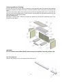
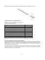
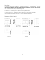
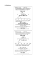
SCAN 60 and 61
INSTRUCTIONS FOR
INSTALLATION AND USE
T es te d &
L ist ed b y
B ea v e r to n
O r e g o n U SA
O M N I-T e s t L a bo r a t o r ie s , In c.
Save these instructions
February 2004
KROG IVERSEN & CO. A/S - 5492 VISSENBJERG - DENMARK
Table of Contents:
1. INTRODUCTION............................................................................................................................................................. 3
Safety and environmental testing. ......................................................................................................................................... 3
Important information: .......................................................................................................................................................... 3
SAFETY PRECAUTIONS ................................................................................................................................................... 4
2. INSTALLATION.............................................................................................................................................................. 5
Precaution.............................................................................................................................................................................. 5
Pre Installation Check List: ................................................................................................................................................... 5
The Floor............................................................................................................................................................................... 6
Floor pad at Corner Installation ..........................................................................................................................................7
Ceiling Height ....................................................................................................................................................................... 7
Combustible Wall Clearance for Top Vent Installation ........................................................................................................ 8
Combustible Wall Clearance for Rear Vent Installation ....................................................................................................... 9
Alcove Installation Requirements: ...................................................................................................................................... 10
Mobile Home Installation: US only .................................................................................................................................... 11
Outside air requirements ..................................................................................................................................................... 12
Draft Requirements ............................................................................................................................................................. 12
Chimney Installation: .......................................................................................................................................................... 13
Factory Built Chimney ........................................................................................................................................................ 13
Masonry Chimney ............................................................................................................................................................... 13
Top vent installation............................................................................................................................................................ 13
Chimney Connection........................................................................................................................................................... 14
Rear Vent Installation.......................................................................................................................................................... 15
Combustible Wall Chimney Connector Pass-Throughs...................................................................................................... 16
Chimney height requirements: ............................................................................................................................................ 17
3. INSTRUCTIONS FOR USE........................................................................................................................................... 18
Ash Drawer ......................................................................................................................................................................... 18
Ash Grate ............................................................................................................................................................................ 18
Baffle Plates ........................................................................................................................................................................ 18
Glass.................................................................................................................................................................................... 18
Smoke Detectors ................................................................................................................................................................. 18
Room Ventilation ................................................................................................................................................................ 18
Fire Box Lining ................................................................................................................................................................... 18
Ceramic Packing Cord ........................................................................................................................................................ 19
Protected Wall Reduced Clearances.................................................................................................................................... 19
Combustion Air Supply....................................................................................................................................................... 19
4. OPERATION .................................................................................................................................................................. 20
Fueling the Stove: ............................................................................................................................................................... 20
To start a fire: ...................................................................................................................................................................... 20
Refueling ............................................................................................................................................................................. 20
5. MAINTENANCE ........................................................................................................................................................... 21
Ash Disposal and Removal ................................................................................................................................................. 21
Cleaning of Stove................................................................................................................................................................ 21
Soapstone ............................................................................................................................................................................ 21
Removing Baffle for Cleaning. ........................................................................................................................................... 22
Air Tube removal: ............................................................................................................................................................... 22
Remove the screw (pos.3) on the right air tube collar (pos.2). .................................................................................. 22
Slide the air tube collar (pos.2) to the left, swing the air tube (pos.1) down and remove it. ................................. 23
Replacement Part List SCAN 60 and 61. ............................................................................................................................ 23
Creosote Formation and the Need for Removal .................................................................................................................. 23
Door Glass........................................................................................................................................................................... 24
Dimensions SCAN 60 and 61 ............................................................................................................................................. 24
6. TROUBLESHOOTING .................................................................................................................................................. 25
7. WARRANTY CONDITIONS FOR SCAN WOOD BURNING PRODUCTS.............................................................. 26
8. EPA Sticker..................................................................................................................................................................... 27
2
We welcome you as a new owner of a SCAN wood-burning stove. In purchasing a SCAN stove you
have joined the growing ranks of concerned individuals whose selection of energy systems reflects
both a concern for the environment and aesthetics. The SCAN stove is one of the finest home wood
stoves in the world over. This manual will explain the installation, operation and maintenance of the
SCAN stove. Please familiarize yourself with the owner’s manual before operating your stove and
save the manual for future reference. Included are helpful hints and suggestions that will make the
operation and maintenance of your new stove an easier and more enjoyable experience. We offer
our continued support and guidance to help you achieve the maximum benefit and enjoyment from
your SCAN stove.
1. INTRODUCTION
Please read this entire manual carefully before you install and use your new SCAN stove,
failure to follow instructions may result in property damage, bodily injury or loss of life. This
manual contains important user information. Keep this manual with the stove after
installation is complete.
Safety and environmental testing.
SCAN has been tested by OMNI-Test Laboratories, Inc. of Beaverton, Oregon, and is safety listed
by OMNI to UL 1482, ULC-S627 and EPA certified.
Important information:
No other SCAN stove has the same registration number as yours. The registration number is fixed
to the stove. In case of complaints we request that you have the registration number.
Items included
In the SCAN stove you will find a service box containing the following items:
1 oven mitten
1 set of screws and hexagon spanners
1 bag containing fire starters for the first lightning
3
SAFETY PRECAUTIONS
USE A METAL CONTAINER WITH A TIGHT FITTING LID TO DISPOSE OF ASHES.
NEVER USE GASOLINE, GASOLINE-TYPE LANTERN FUEL, KEROSENE, CHARCOAL
LIGHTER FLUID, OR SIMILAR LIQUIDS TO START OR “FRESHEN UP” A FIRE IN THIS
STOVE. KEEP ALL SUCH LIQUIDS WELL AWAY FROM THE STOVE WHILE IT IS IN
USE.
DO NOT BURN GARBAGE OR FLAMMABLE FLUIDS SUCH AS GASOLINE, NAPHTHA
OR ENGINE OIL.
THIS STOVE IS HOT WHILE IN OPERATION. DO NOT TOUCH, AND KEEP CHILDREN,
CLOTHING AND FURNITURE AWAY. CONTACT MAY CAUSE SKIN BURNS. USE
GLOVES WHEN STOKING THE FIRE.
DO NOT CONNECT THIS STOVE TO A CHIMNEY FLUE CONNECTED TO ANOTHER
STOVE OR APPLIANCE.
DO NOT CONNECT TO ANY AIR-DISTRIBUTION DUCT OR SYSTEM.
BE SURE TO ALLOW AN ADEQUATE SOURCE OF FRESH AIR INTO THE ROOM
WHERE THE STOVE IS OPERATING (SEE ROOM VENTILATION PAGE 16 AND
COMBUSTION AIR SUPPLY PAGE 17).
DO NOT OPERATE THE STOVE WITHOUT THE FIREBOX BAFFLE PLATES PROPERLY
INSTALLED.
BUILD FIRES DIRECTLY UPON THE HEARTH INSIDE THE STOVE. DO NOT USE
GRATES, IRONS, OR ANY OTHER METHOD TO ELEVATE THE FIRE.
THE SCAN STOVES ARE NOT USABLE FOR FIREPLACE INSTALLATION.
FOR USA ONLY:
WHEN INSTALLING IN A MOBILE, THIS APPLIANCE MUST BE BOLTED TO THE
FLOOR, HAVE OUTSIDE AIR SOURCE FOR COMBUSTION, AND NOT BE INSTALLED
IN THE BEDROOM (PER H.U.D. REQUIREMENTS). CHECK WITH LOCAL BUILDING
OFFICIALS.
FOR CANADA ONLY:
DO NOT INSTALL IN A MOBILE HOME
4
2. INSTALLATION
Precaution
If your SCAN stove is not properly installed, operated and maintained, a house fire may result. For
your safety, follow all installation, operation and maintenance directions. Contact your local building
officials about restrictions and installation requirements in your area.
Pre Installation Check List:
Before you begin an installation, review your plans and check to see that:
1. Your stove and chimney connector will be far enough from combustible material to meet all
clearance requirements.
2. The floor protection is large enough and is constructed properly to meet all requirements.
3. You have all necessary permits from local authorities. Your local building official is the final
authority for approving your installation as safe and determining that it meets all local and state
building and safety codes.
The metal label permanently attached to the back of every SCAN stove shows that it has been
tested to current UL and ULC safety standards, and gives the name of the testing laboratory.
Clearance and installation information is also printed on the label. Local authorities will generally
accept the label as evidence that, when the stove is installed according to the information on the
label and in this manual, the installation meets codes and can be approved.
Codes vary in different areas. Before starting the installation, review your plans with the local
building authority. Your local dealer can provide any additional information needed.
For any unresolved questions about installation in the USA, refer to the national Fire Protection
Association’s publication ANSI/NFPA 211 Standard for Chimneys, Fireplaces, Vents and Solid Fuel
Burning Appliances. For installation in Canada, refer to CSA CAN-B365, Installation Code for Solid
Fuel Burning Applications and Equipment. These standards are the basis for many national codes.
They are nationally recognized and are accepted by most local authorities. Your local dealer or your
local building official may have a copy of these regulations.
NOTE: NFPA 211 6-5.1.1 Chimney Connector and Vent connector Clearances from
Combustible material: Exception: That your Scan stove is listed for installation with a
clearance of less than 12" shall be installed in accordance with the terms of their listing and
the manufacturer's instructions.
WARNING: Check all local building and safety codes before installation. The installation
instructions and appropriate code requirements must be followed exactly and without compromise.
Alterations to the stove are not allowed. Do not connect the stove to a chimney system serving
another stove, appliance or any air distribution duct. Failure to follow these instructions will void the
manufacturers warranty.
NOTE: If you plan to vent your stove into an existing masonry chimney, have the chimney inspected
by a local fire marshal or qualified installer. Remember that the chimney and its location on the roof
heavily influent on the stove performance. An oversized flue may not provide effective draught and a
flue liner may be required. (Observe draft requirements). Consult your dealer or qualified installer
before final selection is made.
We advise you to leave enough room to enable cleaning between the stove and the wall.
5
NOTE: The clearances expressed in inches are those approved for installation in the United States.
The clearances in expressed in millimeters are those approved for installations in Canada. Different
test standards for the respective countries may result in differences in the clearance requirements.
The Floor
One of the main necessary precautions when installing a wood stove is to leave sufficient space
between the stove (top, sides, back, front, and under stove pipes) and any other material that can
catch fire.
NOTE: the floor protection need's only to be a standard ember protection.
Floor pad at Parallel Installation
Model
Floor protection
Scan 60 USA
Scan 60 Canada
Scan 61 USA
Scan 61 Canada
A
16”
457
16”
457
B
203
203
Parallel installation
6
C
9,5”
317
9,5”
317
D
8”
8”
E
43,8”
1240
42”
1192
F
33,7”
1010
33,7”
1010
Corner installation
Floor pad at Corner Installation
Model
Floor protection
Scan 60
USA
Scan 60
Canada
Scan 61
USA
Scan 61
Canada
A
16”
457
16”
457
B
7,5”
203
7,5”
203
C
73,8”
1975
68”
1983
D
104,5”
2794
96”
2804
In a rear vent installation the floor protection must also extend under the stovepipe a minimum of 2”
(50mm) beyond either side of the pipe.
Ceiling Height
Do not install in an alcove or confined space and do not install in a room with a ceiling high below 7’
(210 cm)
7
Combustible Wall Clearance for Top Vent Installation
If the stove is to be placed at side and back walls of combustible materials the following clearances
must be kept
Parallel and corner installation
Model
Connector pipe
Scan 60 USA
Single wall
A
13
B
10.5
C
21
D
12
E
7.5
F
13.5
Scan 60
Canada
Single wall
330
265
535
305
190
343
Scan 60
USA
Double wall
8
6
21
12
5.5
13.5
Scan 60
Canada
Double wall
205
152
535
305
140
340
Scan 61
USA
Single wall
11
10.5
21
12
7.5
13.5
Scan 61
Canada
Single wall
279
265
535
305
190
340
Scan 61
USA
Double wall
6
6
21
12
5.5
11.5
Scan 61
Canada
Double wall
152
152
535
305
138
290
Parallel installation
Corner installation
8
Combustible Wall Clearance for Rear Vent Installation
If the stove is to be placed at side and back walls of combustible materials the following clearances
must be kept:
Rear outlet through wall
Model
Scan 60 & 61
Scan 60 & 61
USA
Canada
Connector pipe
Single wall
Single wall
B
5.25
133
C
21
535
D
12
304
Refer to the manufacturer’s instructions concerning installation of listed single wall connector pipe,
wall thimble and chimney
9
Alcove Installation Requirements:
Whenever the stove is placed in a location where the ceiling height is less than 7’ tall, it is
considered an alcove installation. Because of the reduced height, the special requirements listed
below must be met.
Alcove installation:
Model
Scan 60
Scan 60
Scan 61
Scan 61
USA
Canada
USA
Canada
Connector pipe
Double wall
Double wall
Double wall
Double wall
A
60
1525
60
1525
10
B
48
1210
48
1210
C
21
535
21
535
D
12
304
12
304
E
12.5
315
12.5
315
F
15
381
13
330
G
33
840
33
840
Mobile Home Installation: US only
In addition to standard installation the following requirements are mandatory for installation in a
mobile home.
The stove must be permanently bolted to the floor of the mobile home using the floor screws
provided.
Note: If the composition of the manufactured (mobile) home floor is of light particleboard
construction, you will be required to secure the stove with regular hex head bolts and nuts. This will
ensure that the bolts will not rip out of the floor when the manufactured (mobile) home is being
moved.
The stove must have permanent outside air source for combustion. See Outside Air Requirements
The stove must be electrically grounded to the steel chassis of the mobile home.
A listed chimney system, roof thimble, spark arrestor and roof flashing kit suitable for use in mobile
homes must be used.
The chimney shall be attached directly to the room heater and shall extend at least 3 ft. above the
part of the roof through which it passes. The top of the chimney should project at least 2 ft. above
the highest elevation of any part of the mobile home within 10 ft. of the chimney.
The chimney system shall comply with Local Requirements.
Check local building code as other local codes may apply.
CAUTION: THE STRUCTURAL INTEGRITY OF THE MOBILE HOME ROOF, FLOOR, WALLS
AND CEILING MUST BE MAINTAINED.
WARNING: DO NOT INSTALL IN A SLEEPING ROOM OF A MOBILE HOME.
CAUTION: Do not obstruct combustion air opening when the stove is in use.
Note: Listed factory built chimney connectors including elbows are acceptable for use in mobile
home installations.
11
Outside air requirements
Required for mobile home and in certain localities (Check with building officials)
Outside air must not be drawn from an enclosed space (garage or other unventilated spaces)
When using outside air, find a location where the chimney and outside air hole do not interfere with structural members
of the home.
Connect a 4" (100 mm) diameter stainless steel or other non-combustible corrosion resistant material, to the O.S.A hookup box.
Run the pipe to the outside avoiding sharp bends and turn the end down and fit a corrosion resistant mesh to prevent the
entry of leaves and rodents, seal all the penetration of the outside wall.
Draft Requirements
SCAN stoves are only one component of the total system. The venting system is equally important
for achieving the required flow of combustion air to the firebox and for safely removing unwanted
combustion by-products from the appliance. If the venting system’s design does not promote these
ends, the system may not function properly. Poorly functioning venting systems may create
performance problems as well as become a safety hazard (i.e. an oversized chimney may result in
less than optimum performance. Installations into a large, masonry chimney may require a liner to
improve performance). A draft test should read greater than .04" W.C. (Inches Water Column) and
less than .08" W.C. The table below shows the dimension of the connection piece as well as data
for the draft requirements for the stove:
USA
Canada
Connection
piece
ø 6”
ø152
With Closed Doors
Chimney
draught
0.05” WC
13 Pa
Efficiency
in %
63%
63 %
BTU
8.700 - 2900
8.700 - 2900
The chimney draught depends on the weather conditions. In stormy weather, you may reduce the
chimney draught by closing the damper in the smoke pipe (if a damper has been installed). If the
chimney draught is strong, the combustion air supply must be reduced additionally.
12
Chimney Installation:
Do not connect this unit to a chimney flue serving another appliance. Do not connect to any
air distribution duct or system.
The stoves are listed for installation as a vertically top or rear vented stove using a listed class A
(UL103HT) for Canada (CAN/ULC-S629) factory built chimney exiting through the ceiling/attic/roof.
The inside diameter of the chimney, connector pipe must not be smaller than 6” (152 cm) diameter.
Single wall 24 gauge MSG (0.58 – 0.71 mm) and adapter must not be smaller than 6” (152 mm),
may be used in the room where the stove is installed, follow the chimney manufacturer’s instruction
for installation of chimney and chimney adapter. In Canada, where passage through wall, or
partition of combustible construction is desired, the installation shall conform to CAN/CSA B365.
Factory Built Chimney
When a metal prefabricated chimney is used, the manufacturer’s installation instructions must be
followed. You must also purchase (from the same manufacturer) and install the ceiling support
package or wall pass-through and “T” section package, fire stops (where needed), insulation shield,
roof flashing, chimney cap, etc. Maintain proper clearance to the structure as recommended by the
manufacturer. The chimney must be the required height above the roof or other obstructions for
safety and proper draft operation. See page 15 for Chimney Height Requirements.
Masonry Chimney
Ensure that a masonry chimney meets the minimum standards of the National Fire Protection
Association (NFPA) by having it inspected by a professional. Make sure there are no cracks, loose
mortar or other signs of deterioration and blockage. Have the chimney cleaned before the stove is
installed and operated. When connecting the stove through a combustible wall to a masonry
chimney, special methods are needed. Refer to Combustible Wall Chimney Connector Passthrough on page 14.
Top vent installation
The stove is preset for top vent from
the factory.
Required installation components:
• Chimney cap
• Insulated chimney
• Storm collar
• Roof flashing
• Ceiling support box or joist
shield/fire stop spacer
• Chimney connector pipe
• Chimney connector adapter
13
Chimney Connection
The chimney connector is ether a single or double walled pipe, depending on the type of installation,
used to connect the stove to the chimney. For use with the SCAN woodstoves the chimney
connector MUST be 6” in diameter, with a minimum thickness of 24 gauge black steel or 26 gauge
blued steel.
Aluminium and galvanized steel pipe is not acceptable for use with the SCAN woodstove. These
materials cannot withstand the extreme temperatures of a wood fire and can give off toxic fumes
when heated.
NOTE:
Listed vent connectors shall be installed in accordance with the terms of their listing and the
connector manufacturer’s installation instructions.
Do not use the connector pipe as a chimney.
Each chimney connector or stovepipe section must be installed to
the stove flue collar and to each other with the male (crimped) end
toward the stove. See fig 5.
Fig. 5
This prevents any amount of condensed or liquid creosote from running down the outside of the
pipe or the stovetop. All joints, including the flue collar connection must be secured with three sheet
metal screws to ensure that the sections do not separate.
For the best performance the chimney connector should be as short and direct as possible, with no
more than two 90° elbows. The maximum horizontal run is 36” and a recommended total length of
stovepipe should not exceed 10 feet. Always slope horizontal runs upward ¼” per foot toward the
chimney.
No part of the chimney connector may pass through an attic or roof space, closet or other concealed
space, or through a floor ceiling. All sections of the chimney connectors must be accessible for
cleaning. Where passage through a wall or partition of combustible construction is desired, the
installation must conform to NFPA 211 or CAN/CSA-B365, and is also addressed in this manual.
14
Rear Vent Installation
For venting into a masonry or a back standing steel chimney through the top vent the top horizontal
portion of a single wall connector pipe can be located not closer than 18” below a combustible
ceiling.
From the factory the stove is prepared for top mounting of the flue collar, but all SCAN stoves have
an optional flue outlet, therefore the flue collar can be fitted either on the top or at the rear as
required.
Mounting the flue collar for rear outlet for Scan 60, for Scan 61 start at paragraph 4.
1. Remove the top plate.
2. Remove the cover plate on the jacket
3. Remove the part of the inner back plate inside the groove for passing of the flue way to the
rear outlet.
4. Detach the flue collar and turn it to fit for rear outlet and fix it again NOTE ensure that the
gasket is still in right position on the flue collar before you tighten the screws.
5. Reinstall the top plate or wait until you have completed the connection to the chimney.
Rear venting into a masonry or steel chimney through a thimble or other vent configuration than
descript here must follow local codes or NFPA 211 or CAN/CSA-B365 guidelines and methods.
Required installation components:
• Chimney cap
• Insulated chimney
• Tee section
• Tee support bracket
• Chimney connector pipe
• Wall thimble
• Wall strap
15
Combustible Wall Chimney Connector Pass-Throughs.
Method A. 12” (304.8 mm) Clearance to Combustible Wall
Member: Using a minimum thickness 3.5” (89 mm) brick and
a 5/8” (15.9 mm) minimum wall thickness clay liner, construct
a wall pass-through. The clay liner must conform to ASTM
C315 (Standard Specification for Clay Fire Linings) or its
equivalent. Keep a minimum of 12” (304.8 mm) of brick
masonry between the clay liner and wall combustibles. The
clay liner shall run from the brick masonry outer surface to
the inner surface of the chimney flue liner but not past the
inner surface. Firmly grout or cement the clay liner in place
to the chimney flue liner.
Method B. 9” (228.6 mm) Clearance to Combustible Wall
Member: Using a 6” (152.4 mm) inside diameter, listed factorybuilt Solid-Pak chimney section with insulation of 1” (25.4 mm)
or more, build a wall pass-through with a minimum 9” (228.6
mm) air space between the outer wall of the chimney length
and wall combustibles. Use sheet metal supports fastened
securely to wall surfaces on all sides, to maintain the 9” (228.6
mm) air space. When fastening supports to chimney length,
do not penetrate the chimney liner (the inside wall of the SolidPak chimney). The inner end of the Solid-Pak chimney
section shall be flush with the inside of the masonry chimney
flue, and sealed with a non-water soluble refractory cement.
Use this cement to also seal to the brick masonry penetration.
Method C. 6” (152.4 mm) Clearance to Combustible Wall
Member: Starting with a minimum 24 gage (.024” [.61 mm])
6” (152.4 mm) metal chimney connector, and a minimum 24
gage ventilated wall thimble which has two air channels of 1”
(25.4 mm) each, construct a wall pass-through. There shall
be a minimum 6” (152.4) mm separation area containing
fiberglass insulation, from the outer surface of the wall
thimble to wall combustibles. Support the wall thimble, and
cover it's opening with a 24-gage minimum sheet metal
support. Maintain the 6” (152.4 mm) space. There should
also be a support sized to fit and hold the metal chimney
connector. See that the supports are fastened securely to
wall surfaces on all sides. Make sure fasteners used to
secure the metal chimney connector do not penetrate
chimney flue liner.
Method D. 2” (50.8 mm) Clearance to Combustible Wall
Member: Start with a solid-pack listed factory built chimney
section at least 12” (304 mm) long, with insulation of 1” (25.4
mm) or more, and an inside diameter of 8” (2 inches [51 mm]
larger than the 6” [152.4 mm] chimney connector). Use this
as a pass-through for a minimum 24-gage single wall steel
chimney connector. Keep solid-pack section concentric with
and spaced 1” (25.4 mm) off the chimney connector by way
of sheet metal support plates at both ends of chimney
section. Cover opening with and support chimney section on
both sides with 24 gage minimum sheet metal supports. See
that the supports are fastened securely to wall surfaces on all
sides. Make sure fasteners used to secure chimney flue liner.
16
NOTES:
1. Connectors to a masonry chimney, excepting method B, shall extend in one
continuous section through the wall pass-through system and the chimney wall, to
but not past the inner flue liner face.
2. A chimney connector shall not pass through an attic or roof space, closet or
similar concealed space, or a floor, or ceiling.
Chimney height requirements:
The chimney must extend 3 feet above the level of roof penetration and a minimum of 2 feet higher
than any roof surface within 10 feet. Check with your local building officials for additional
requirements for your area.
The condition of the chimney and height is very important; we suggest a total minimum height of 15’
(4,5m). Measured From the floor level on which the stove is installed.
17
3. INSTRUCTIONS FOR USE
Ash Drawer
The ash drawer located behind the fuel door is designed to make cleaning easier by containing the
ashes in a removable drawer
Ash Grate
Above the ash drawer, located in the floor of the firebox is a rotating ash grate to facilitate
transferring ashes from the firebox into the ash drawer. To operate this grate, pull and push the
handle under the bottom plate in and out several times. Operate stove only with the handle pushed
all the way in.
Baffle Plates
The SCAN stoves have two baffle plates that must be installed in the upper firebox. When in the
proper position, the rear edges of the baffle plates should touch the back wall of the firebox. See the
maintenance section of this manual for additional information on Removing Baffle plates for
Cleaning on page 20.
Ceramic baffle plates are delivered with the stoves. When mounting a baffle plate place it according
to the description in section 5: Removing Baffle for Cleaning. Make sure that it is placed
symmetrically in the stove, i.e. with even amounts of free air space on each side.
We recommend that you treat the ceramic baffle plates (Skamol) with caution because it is a
delicate material (not covered by the limited warranty). It is extremely heat resistant.
Glass
The glass is a heat-resistant ceramic glass that can withstand continuous temperatures up to
1390°F (754°C). This temperature is well beyond the temperatures in which you operate your stove.
These stoves are designed to provide a flow of air over the inside of the glass. This air combined
with high temperatures helps keep the glass optimally clean when the combustion air intake is fully
opened. When operating the stove on low for extended periods of time, the glass may become dirty.
A short, hot fire will help clean off much of the normal sooth buildup (see section 6:
Troubleshooting). In order to keep glass soot-free, the moisture content of the wood must be
between 15 % and 18% on a wet basis.
Smoke Detectors
Since there are always several potential sources of fire in any home, we recommend installing
smoke detectors. Do not install them too close to the stove as heat can activate them.
Room Ventilation
During the combustion, oxygen taken from the room air is used. In rare cases it may be necessary
to mount a fresh-air duct on the stove. Please refer to your local building codes.
Fire Box Lining
The firebox is lined with Skamol, which is a high heat resisted and isolations material
We recommend that you treat the lining plates (Skamol) with caution because it is a delicate
material (not covered by the limited warranty
18
Ceramic Packing Cord
These stoves are equipped with a ceramic packing cord to ensure the tightness of the doors and the
glasses. This packing cord is a wearing part and must be changed from time to time. Please consult
your authorized dealer in this case.
Protected Wall Reduced Clearances
Local codes in some areas will allow reduced clearances when the stove is installed adjacent to a
protected wall system. Your local building official must approve the variance. Check your local
building codes or with a qualified installer.
Combustion Air Supply
Provide for an adequate supply of air for combustion. Proper ventilation is essential when using a
solid fuel-burning appliance. The combustion process uses oxygen from inside the dwelling. If there
is not adequate make-up air (as there is in newer homes which are well-insulated and weathertight), it may be difficult to obtain an adequate draft in your chimney (caused by a shortage of air in
the house). To correct this, it may be necessary to crack a window on the windward side of the
dwelling, or provide combustion air to a nearby floor/wall vent (fresh-air duct), or directly to the
stove.
19
4. OPERATION
WARNING:
DO NOT USE GASOLINE, LIGHTER FLUID, KEROSENE OTHER FLAMMABLE LIQUIDS TO
START OR FRESHEN A FIRE IN THE STOVE KEEP ALL SUCH LIQUIDS WELL AWAY FROM
THE STOVE WHILE IT IS IN USE.
Fueling the Stove:
Your SCAN freestanding wood stove is designed for burning dry, natural, well-seasoned wood only.
(If your wood supply is not seasoned, ask your authorized SCAN dealer where to obtain seasoned
fuel in your area). Wood should be stored in a dry place for at least one year before being used for
fuel. Some trees have very high moisture content and it is necessary to thoroughly dry the wood.
Cutting and splitting the wood, then stacking it with both ends of the wood exposed, can speed up
the drying process. More drying occurs through the end than through the sides even when the wood
is split. We recommend that the moisture content of the wood is between 15 %-18%.
Green or uncured wood does not work well as fuel, and can cause increased creosote buildups.
The value of green wood as a source of heat is limited. Do not overload, use kindling wood, or mill
ends for primary fuel as this may cause over-firing.
Do not store wood within the installation clearances or within the space required for charging and
ash removal.
Although feeding excessive amounts of fuel to the stove should be avoided, it is important to supply
it with sufficient fuel to maintain a moderately hot fire (this is particularly important since burning
wood produces volatile substances).
Burning materials other than natural dry well seasoned wood may shorten the life of your stove and
possibly lead to a dangerous over-firing condition. Do not burn garbage, particle, board, scraps or
pressed logs that use bonding agents because they can produce conditions, that will deteriorate
metal.
Starting a Fire: Do not elevate the fire. Build fire directly on the hearth inside the stove; do not build
fire above or in front of the log retainer.
To start a fire:
Pull the start device and air intake control to fully open. In addition, to help with the start-up, you
may also leave the fuel door slightly ajar. Use a small amount of fire starters with enough kindling
wood to establish a small, brisk fire. Add several larger pieces of wood on top of the burning kindling
and allow enough time for it to fully catch on fire. Add a full load of fuel and close and latch the fuel
door. After five minutes, push the start device to closed position and adjust the air intake control to
the desired position.
Refueling
To refuel the stove, first move the air intake control to full open, let the fire “liven-up” for about one
minute. Open the fuel door about ½” and hold in this position until stove is drafting well. Open the
fuel door and add wood. If the fire or coal bed is almost depleted and a full load of wood is added, it
may be necessary to adjust the air intake control wide open to reestablish a lively fire. The use of
start up air should only be used for a short period of time.
Note: After refueling, when the wood is burning at a brisk rate, reset the air intake control to the
desired position by moving the air intake control handle all the way closed and then back to the
desired setting.
20
5. MAINTENANCE
Ash Disposal and Removal
CAUTION: Be sure the fire is out and the stove is cold before removing ashes!
Be careful when you empty the stove for the ashes. There may be embers left up to 24 hours after
the stove was last used. Ashes should be placed in a metal container with a tight fitting lid. The
closed container of ashes should be places on a non-combustible floor or on the ground well away
from all combustible materials, pending final disposal.
If ashes are disposed of by burial in soil or otherwise locally dispersed, they should be retained in
the closed container until all cinders have thoroughly cooled.
Cleaning of Stove
The stove is cleaned with a moist cloth. Senotherm spray is available for repair of possible
damages/scratches. Your dealer has the right spray in the right color. As there may be minor color
differences, it is recommended to repair large areas with natural borders. You will get the best result
if the stove is repaired while it is lukewarm (if the stove is too hot the paint will be granular).
Remember a good airing during the repair. A possible change of color to gray is caused by overfiring, i.e. you have used more wood than recommended.
Soapstone
The soapstones are cleaned with fine sandpaper or a dry sponge.
21
Removing Baffle for Cleaning.
Be sure the fire is out and the stove is cold before removing baffle plate. Be cautions with handling
the plates because the plates are made of a delicate material; which easily broke if not handle with
care.
Removal of the lower plate: lift the plate (pos.9) up from the supporting pins (pos.11) and take the
pins out from the side plates (pos.6, pos.8) and take out the plate. Use the same procedure for the
upper plate (pos.10) and take out plate.
See the drawing below:
Mounting in reverse order, observe: the plates are placed as such that the supporting pins fit into
the groove in the plates.
WARNING:
Do not operate stove without Baffle plates properly installed or warranty will be void.
Air Tube removal:
Remove the screw (pos.3) on the right air tube collar (pos.2).
22
Slide the air tube collar (pos.2) to the left, swing the air tube (pos.1) down and remove it.
Replacement Part List SCAN 60 and 61.
Caution: Use only original SCAN replacement part.
Do not use substitute materials.
Replacement part
Glass panel for the door SCAN 60
Glass panel for the door SCAN 61
Gasket for the glass
Door gaskets
Baffle plate upper SCAN 60
Baffle plate upper SCAN 61
Baffle plate lower SCAN 60
Baffle plate lower SCAN 61
Firebox lining SCAN 60
Firebox lining SCAN 61
Upper part for shaking grate
Shaker grate, complete
Secondary air tube
Part #
57600011
57610011
55300019
55300021
54600000 091
54610000 091
54600000 0911
54610000 0911
53600000 091
53610000 091
50100110
50100111
Creosote Formation and the Need for Removal
When wood is burned slowly it produces tar and other organic vapors, which combine with expelled
moisture to form creosote. The creosote vapors condense in the relatively cool chimney flue of a
slow-burning fire. As a result, creosote residue accumulates in the flue lining. When ignited this
creosote makes an extremely hot fire.
The chimney connector and chimney should be inspected at least twice monthly during the heating
season to determine if a creosote buildup has occurred. If creosote has accumulated it should be
removed to reduce the risk of a chimney fire.
23
Door Glass
A commercial glass cleaner designed for stoves is recommended for cleaning the glass. The glass
can also be cleaned as follows: Dip a moist cloth or old newspaper in the ashes and use this to
clean the glass. Attention: The ashes should not get into contact with your skin! Wipe with a dry
cloth. The ceramic door packing cord must not get wet.
Be careful not to abuse the glass by striking or slamming the door shut.
Do not operate the stove with broken glass. If the glass breaks then replace it promptly.
Use only replacement packing cord listed for the door, glass and ash drawer.
Dimensions SCAN 60 and 61
SCAN 61
SCAN 60
24
6. TROUBLESHOOTING
Smoke:
- Insufficient chimney draught!
- Check if the chimney has the right dimension.
- Check if the smoke pipe or chimney is blocked.
- Check if the chimney has the right height compared to the surroundings.
- Wood with excessive moisture content.
The wood burns too fast:
- Are the air valves adjusted correctly according to the instructions?
- Is the smoke deflector plate placed correctly?
Soiled glass:
- Is the combustion air valve adjusted according to the instructions?
- Is the wood dry?
Polluted chimney:
- Incorrect combustion
- Is the wood dry?
The shaking grate is stuck:
- Check if a piece of wood, a pin or the like is stuck.
- Is the bar placed/mounted correctly?
The stove’s surface turns gray:
- Over heating - please refer to the maintenance section: Cleaning of Stove.
The stove does not heat:
- Use of moist wood. Extra energy is used to dry the wood.
25
7. WARRANTY CONDITIONS FOR SCAN WOOD BURNING PRODUCTS
All SCAN wood stoves; inserts and fireplaces are subject to a strict quality control, before they are
shipped to the customer and end user. However, should an error occur, we back all SCAN wood
burning stoves, inserts, and fireplaces with an extensive five years limited warranty.
The warranty covers all parts that may require replacement from a failure that was caused in the
judgment of SCAN, to be a defect in material or workmanship.
This warranty is given to the first retail purchaser only (other than for the purposes of resale) and is
not transferable. This warranty does not cover damage resulting from other than defects in material
or workmanship or damage caused by unreasonable use including the failure to provide reasonable
and necessary maintenance. In addition, this warranty does not cover repairs performed due to
neglect, abuse, or use of the stove/insert/fireplace other than in the application for which it is
designed.
Specifically this warranty does not cover:
• Wearing parts, such as firebricks, baffle plate, shaking grate and gaskets (other than
damages that are visible at the time of delivery)
• Glass (other than damages that are visible at the time of delivery or damages that occur
during the first fire)
• Transport costs
• Dismounting/mounting
The warranty is invalid if the serial number for your SCAN stove/insert/fireplace is removed or
defaced or if service for defects covered under this warranty is performed by other than an
authorized SCAN dealer or SCAN factory recommended service person.
This warranty is void if installation is not in conformity with installation's instructions and/or local fire
and building regulations.
This warranty applies only to SCAN stoves/inserts/fireplaces sold within the United States of
America and Canada.
This limited warranty is in lieu of all other express warranties, any implied warranty of
fairness for a particular purpose, merchantability, or otherwise, applicable to this product,
shall be limited in duration to the duration of this limited warranty. Scan shall not be liable
for any special, incidental, or consequential damages, whether based on lost goods or
otherwise.
Some states so not allow limitations on how long any implied warranty lasts, so the above
limitation may not apply to you. Some states do not allow the exclusion or limitation of
incidental or consequential damages, so the above limitation or exclusion may not apply to
you.
This warranty gives you specific legal rights, and you may have other rights, which vary from state
to state.
26
8. EPA Sticker
27